

Blizzard Ski Ski 760LD, Ski 700LD, Ski 800, Ski 760 User Manual

Assembly & Operation Manual
Blizzard Straight Blade Snowplows
Models 700LD, 760LD, 760 & 800

i Table of Contents
Introduction
Congratulations on purchasing the finest
straight blade snowplow available!
Blizzard straight blades are clearing
new trails for innovative design, rugged
durability, quality craftsmanship and
superior performance. Our exclusive
products are manufactured and tested
in Michigan’s Upper Peninsula, the
snow capital of the Midwest. With an
annual snowfall averaging over 250,"
we couldn’t imagine building snow
removal products anywhere else!
Your Blizzard straight blade is equipped
with versatile features designed f or years
of dependable service. The hydraulic
draw latch mounting system positively
aligns the plow for fast installation or
removal. All Blizzard straight blade
snowplows feature an extended moldboard.This unique construction provides
an additional 5" of blade that rolls snow
farther ahead and to the side when
plowing. Now you can move snow
faster, saving fuel and reducing wear
on your truck and plow. Safety features
include full moldboard trip action,
enclosed hydraulics and automatic
cylinder pressure relief.
To ensure years of optimum snowplow
performance, review the contents of this
manual. It contains assembly information, detailed diagrams, complete parts
listings, maintenance guidelines and
troubleshooting tips.
Should you need additional information,
contact your local Blizzard snowplow
dealer.Their knowledgeable staff is well
informed on the latest straight blade
information.They are also your source
for replacement parts, technical assistance and all service repairs.
Comments, suggestions or concerns?
Address all correspondence to:
Blizzard Corporation
Customer Service Department
95 Airpark Boulevard
Calumet, MI 49913
Table of Contents
01 Snowplow Accessories
02 Warning!
03 Snowplow Operation
Assembly Instructions
04 Unpacking & Inspection
05 Moldboard & A-frame Assembly
09 Electrical Assembly - Plow Harness
10 Electrical Assembly - Vehicle Harness
12 Testing The Snowplow
14 Mounting & Dismounting Instructions
Maintenance & Plow Specifications
15 Regular Maintenance
16 Storing Y our Snowplow
17 Plow Specifications
Plow Diagrams & Part Lists
18 Models 700LD, 760LD, 760 & 800 Parts List
22 Models 700LD, 760LD, 760 & 800 Assembly Schematic
24 Manifold Detail with Hydraulic & Electrical Schematics
Electrical Diagrams
25 Molded Plug Pin Locations
26 Plow Harness
27 Plow Harness Wire Schematic
28 Main Lighting Harness - Relay Version
29 Main Lighting Harness - Relay Version Wire Schematic
30 Vehicle Har ness
31 Vehicle Har ness Wire Schematic
32 On/Off Switch Leads & Ground Lead
Torque Specifications
33 Bolts & Hydraulic Adapters
Troubleshooting
34 Troubleshooting Guide
Warranties
36 Limited Consumer Warranty
37 Commercial Warranty
Blizzard Snowplow Airfoil
P/N 81041 (700LD & 760LD)
P/N 52093 (760 & 800)
Help channel air flow to
your truck radiator during
the long haul over the road.Mounted front and center, our custom
airfoil redirects air over the top of the b lade and into the grill of your
vehicle.Don’t get stuckon the side of the road! Keep trucking with
this easy-to-install accessory.The airfoil is shipped with complete
mounting hardware.
Blizzard Snowplow
Touch-Up Paint
P/N 61219 (Gloss White)
P/N 63073 (Gloss Black)
Putting your snowplow away for
the winter? Have a deep scratch
to cover? Clean up your blade and
plow parts with our gloss spray
paints. Made to match your original plow equipment, Blizzard
snowplow touch-up paint provides an excellent finish to help keep
your snowplow looking its best.Paint provided in 12 oz.spray cans.
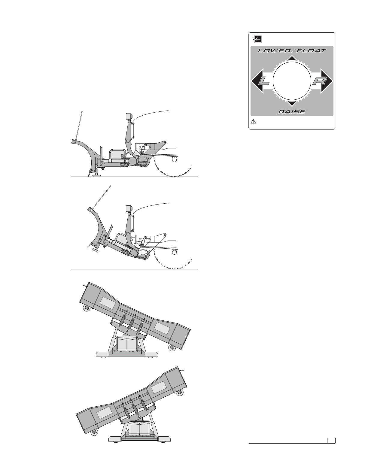
Blizzard Snowplow Rapid
Action Hydraulic Oil
P/N 63070 (Quart)
P/N 63071 (12 Quarts/Case)
Blizzard hydraulic oil is specially
formulated for use in Blizzard
snowplows.This zinc-free product
can significantly enhance the
operation and performance of the hydraulic system in the most
inclement weather conditions. Blizzard Snowplow Rapid Action
Hydraulic Oil maintains its viscosityto temperatures as low as -60˚F.
Blizzard hydraulic oil is available by the quar t or case.
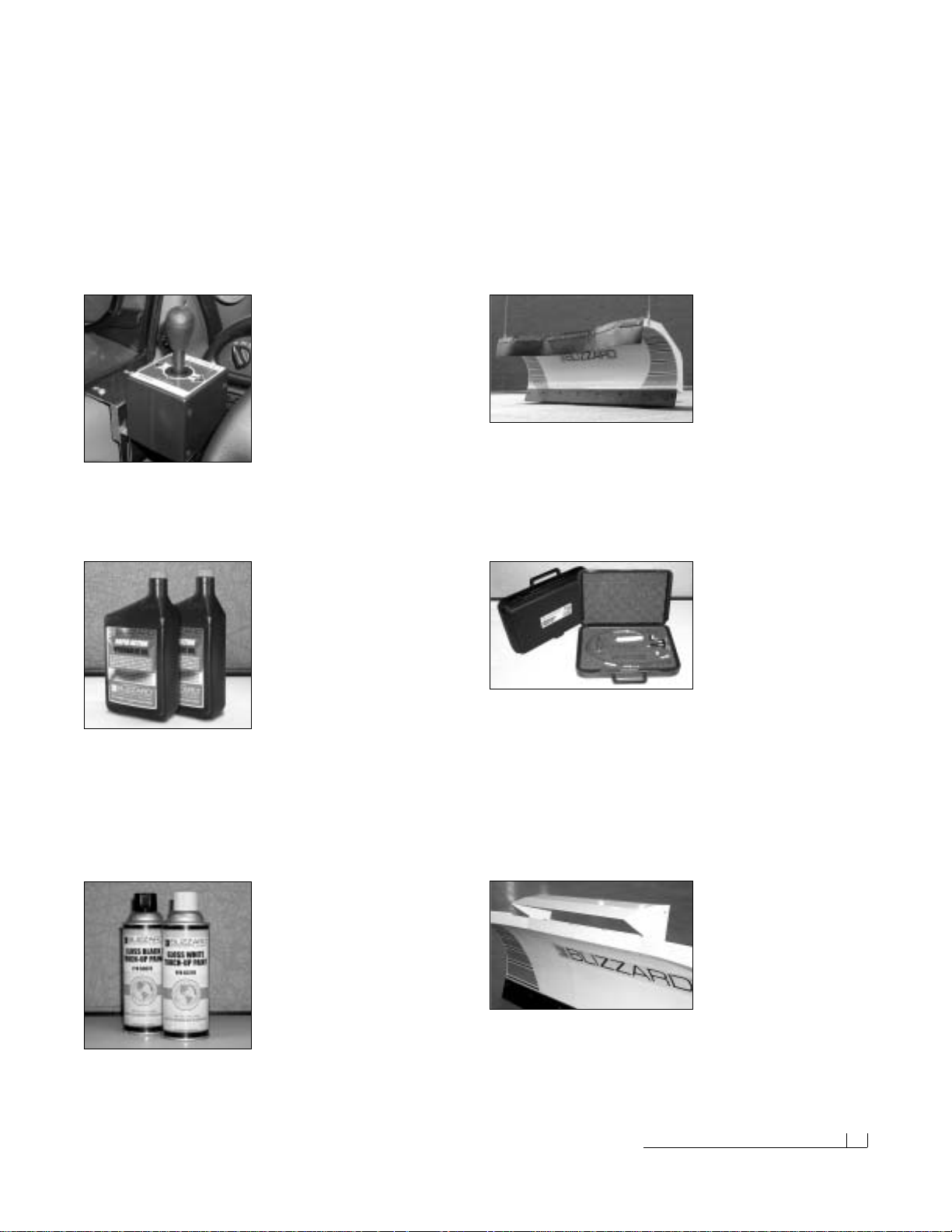
Straight Blade Joystick
Window Mount Bracket
P/N 61261
This adjustable bracket mounts
easily to your straight blade joy-
stick control and installs quickly
onto any door panel. Ideal for left
hand joystick operation or for
vehicles with center consoles.The window mount bracket is shipped
complete with hardware.Some assembly required.
Snowplow Accessories 01
Snowplow Accessories
All of the accessories pictured below are currently offered for your snowplow. See your local Authorized Blizzard Dealer for pricing and availability.
Visit our web site at www.blizzardplows.com to view new snowplow
accessories and our latest Blizzard snowplow wearables.
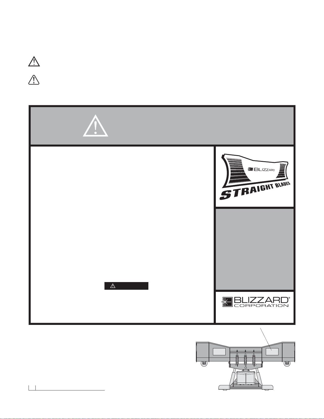
Rubber Snow Deflector
P/N 81040 (Model 700LD)
P/N 61243 (Model 760LD)
P/N 61242 (Model 760)
P/N 61260 (Model 800)
Plow safer and easier with
our custom rubber snow deflector.This easy-to-install accessory
keeps snow off of your windshield and in its place—on the ground!
Rugged and durable, the 3/8" thick, 2-ply construction is made to last.
All snow deflectors are shipped with complete mounting hardware.
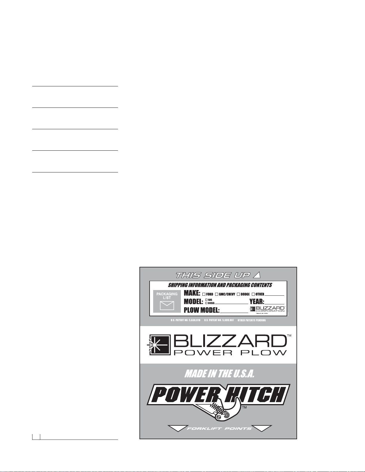
Blizzard Snowplows
Emergency Parts Kit
P/N 63074
Be prepared for unexpected
plow emergencies! This kit
includes the most common
replacement parts conveniently packaged in a small, durable plastic
case.Custom foam insert holds the following plow parts:Angle cylinder hose, lift cylinder hose, hitch pin w/hair pin cotter, angle cylinder
clevis pin w/cotter, 90˚ angle cylinder fitting, solenoid, Power Hitch™
toggle switch, corrosion prev entive compound (2 oz.) and 10A fuse .
The compact case (13.5"x9" x3.3") allows for easy storage behind
or under your truck seat.
02 Warning!
Warning!
Prior to operating your straight blade, review the WARNING! label at the
passenger’s side rear of the moldboard (shown below).
Note: Read and understand all warnings indicated in this manual prior to
operating the snowplow. Warnings and cautions in the manual are indicated
by the icons shown to the left.
WARNING:
CAUTION:
1. Properly mount the snowplow prior to moving the vehicle.
2. To prevent accidental plow activ ation, turn the Power switch on the snowplow control
to the “OFF” position when not in use.
3. Stand clear of the attachment area when mounting the snowplow to the undercarriage
and operating the Power Hitch Connect/Disconnect switch. Failure to do so may
result in serious injury or death.
4. Securely position all mounting pins prior to operating your snowplow.
5. Do not position your body between the snowplow and the vehicle when servicing
or operating.
6. Position snowplow in such a manner as to not block your vision or plow headlights
while in transit.
7. Do not change the position of the snowplow while in transit.
8. Do not exceed 40 mph when transporting the snowplow.
9. Do not exceed 10 mph when plowing.
10. Always lower the snowplow when the vehicle is parked.
11. Vehicles equipped with air bags are designed to be activated in a frontal collision
equivalent to hitting a solid object or barrier at approximately 14 mph or more.
Careless or high speed driving while plowing snow, which results in vehicle impact
deceleration equivalent to or greater than the airbag deployment threshold described
above, would deploy the airbag.
Blizzard straight blade snowplows are protected by U.S. Patent 6,276,076 B1. Other patents pending.
READ
OWNER’S
MANUAL
THOROUGHLY
PRIOR TO
OPERATING
PLOW.
Calumet, Michigan 49913
BLZ 1024
WARNING
WARNING
Should the WARNING! label or any of the labels
that came with your snowplow become hard to
read or wear off, contact your local Authorized
Blizzard Dealer for replacements.
Snowplow Operation 03
Snowplow Operation
Your snowplow is the most advanced and versatile straight blade on the
market.The easy-to-use joystick control allows you to automatically adjust
the plow blade into an infinite number of plowing positions. Review the
illustrations below for instruction on maneuvering your snowplow.
A.
B.
C.
D.
A. Lowered or Float Position
Pushing the joystick forward, toward the “Lower/
Float” designation on the label, will lower your
straight blade to the ground.Pushing the joystick
ahead until the detent “locks”the control will allow
the snowplow to “float”, or follow the contour of
the ground when moving forward or backward.
B. Raised Position
Pulling the joystick back, toward the “Raise”
designation on the label, will lift your straight
blade off of the ground. To stop raising the plow,
simply return the joystick to its “neutral”or center
position.The snowplow has reached its maximum
raised position when the blade stops lifting –
return the joystick to its neutral position.
C. Angled Right Position
To angle your straight blade to the right, position
the joystick toward the “R” on the label. To stop
angling the plow, return the joystick to its “neutral”
or center position.The snowplow has reached its
maximum angled position when the blade stops
moving to the right side.
D. Angled Left Position
To angle your straight blade to the left, position
the joystick toward the “L” on the label. To stop
angling the plow, return the joystick to its “neutral”
or center position.The snowplow has reached its
maximum angled position when the blade stops
moving to the left side.
***** IMPORTANT *****
To prevent premature failure of the power
contactor (solenoid),initiate the plow function
and return the joystick to its neutral or center
position — except float. DO NOT hold the joystick in any position that allows the pump to
continuously run after the plow has reached
its maximum degree of movement. This will
reduce the useful life of the solenoid.
BLIZZARD
To prevent accidental plow activation, turn
POWER switch to the “OFF” position when
not in use.
BLZ 1017
WARNING
®
04 Unpacking & Inspection
Assembly Instructions
Unpacking & Inspection
Your Blizzard straight blade has been packaged to withstand transit and
weather related damage.Fully inspect all components upon receipt of your
plow. In the event of shipping damage or missing parts, immediately contact
our Customer Service Depar tment toll free at 1-888-680-8600.
Begin unpacking and inspection in the following order:
1. Remove the shipping document from the end panel of the pallet wrap.
Retain all documentation for your records.
2. All wood framing and polyethylene material should be removed from
the pallet for easy access to the snowplow.
3. Due to the odd shaped components and size of several assembly
parts, various cable ties and corrugated material are used for scratch
resistance and package orientation. Please remove these items prior
to assembly.
4. Place the main blade assembly on a flat, level surface.
Once you have inspected all parts and removed all packaging materials,
your snowplow is ready to be fully assembled.
Pallet Wrap End Panel
The tear resistant woven polyethylene pallet wrap
contains a moisture barrier to help protect all
packaged components and keep out the most
inclement weather during shipping and storage.
The end panel of the pallet cover contains important information regarding the snowplow model
and the plow’s serial number.Both of these numbers are given together. The first three digits
and/or two letters in the the number indicated is
always the plow model 700LD , 760LD, 760 or 800
– and the entire seven (nine) digit number make
up the entire serial number.The shipping document is also attached to the end panel.Be sure to
retain this list for your records.
Snowplow Serial Number
Hydraulic Pump Serial Number
Telephone Number
Dealer/Distributor
Date of Purchase
Moldboard & A-frame Assembly 05
7/16"
7/16"
45˚ Adjustable Elbow O.R.B.Adapter
9/16"
9/16"
90˚ Adjustable Elbow O.R.B.Adapter
Moldboard & A-Frame Assembly
1. Begin the moldboard assembly by positioning the PIVOT BEAM and
A-FRAME near the connecting points at the rear of the blade between
the two center support ribs. Position the pivot beam between the two
support ribs until the connecting points on the beam align with those
on the plow. Inser t one 3/4"-10 x 3" (2" shank) hex head cap screw
through each mounting hole and secure with a 3/4"-10 top lock nut.
Tighten each nut until it is snug with the pivot beam.
CAUTION:Do not over tighten hex head n uts! Binding may
prohibit the pivot beam from moving properly on the plow.
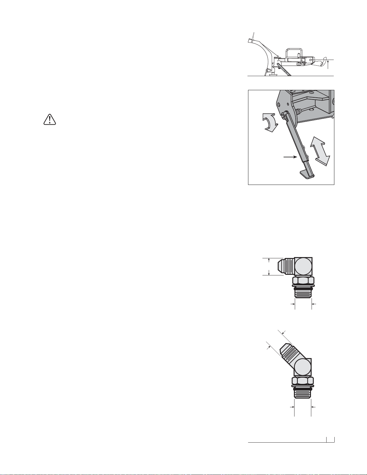
Note:T o aid in the remaining installation, rotate the spring loaded kickstand clockwise until it locks into place.Adjust the foot on the stand
arm so the height of the A-frame, at its mount points, is 12-1/2" to
level ground (See the diagram to the right). Tighten both of the 1/2"-13
top lock nuts on the kickstand.
2. Position each ANGLE CYLINDER with the rod end of the cylinder
in the pivot beam and the hydraulic hose port facing away from the
A-frame.Secure the cylinder to the pivot beam with one 3/4" x 4-1/2"
CLEVIS PIN and one 1/4" x 1-1/2" HAMMERLOCK COTTER PIN.
Note:The hammerlock cotter pin will “lock” itself into place once the
head of the pin is struck. It is not necessary to bend the pin further
upon installation. Extend each cylinder rod until the cylinder base
mounting hole aligns with the hole on the A-frame angle cylinder
bracket. At this point, insert another clevis pin and secure it with a
cotter pin.Repeat the same installation for the opposite angle cylinder.
3. Remove each dust cap from both of the hydraulic angle cylinder ports
and attach one 9/16"-18 x 9/16"-18 90˚ ADJUSTABLE ELBOW O.R.B.
ADAPTER to each port. Note: All of the hydraulic adapters can be
found packaged with the manif old assembly.Reference the table on
page 33 for proper torque specifications. Each adapter should be
angled toward the top of the moldboard.Connect the 3/8" x 24" hydraulic
hose, labeled #1, to the driver’ s side angle cylinder adapter. Attach the
3/8" x 24" hydraulic hose, identified by a #2, to the passenger’s side
angle cylinder adapter.Be careful not to overtighten the hose connections. Route both hoses over the top of each angle cylinder.
4. Next, remove both of the plastic dust caps from the HYDRAULIC
LIFT CYLINDER ports. Attach one 7/16"-20 x 7/16"-20 45˚ ADJUSTABLE ELBOW O.R.B. ADAPTER to the driver’s side port and one
7/16"-20 x 7/16"-20 MALE O.R.B.CONNECTOR ADAPTER to the
passenger’s side port. Once the adapters have been installed on the
cylinder, connect the HYDRAULIC HOSES.Note: Position the fittings
in the cylinder port such that the hoses install directly in the center of
the A-frame access holes.A hose installed too close to the edge of the
opening may work itself free with the operation of the lift cylinder and/
or movement of the plow. The 45˚ adapter on the driver’s side of the
cylinder receives a 1/4" x 17" hose identified by a label containing the
number 3.Connect the 45˚ angle on the hose to the hydr aulic adapter
on the cylinder.The male connector adapter on the passenger’s side
of the cylinder receives a 1/4" x 15" hose identified by a label containing the number 4.Tighten the 45˚ end of the hose to the hydraulic
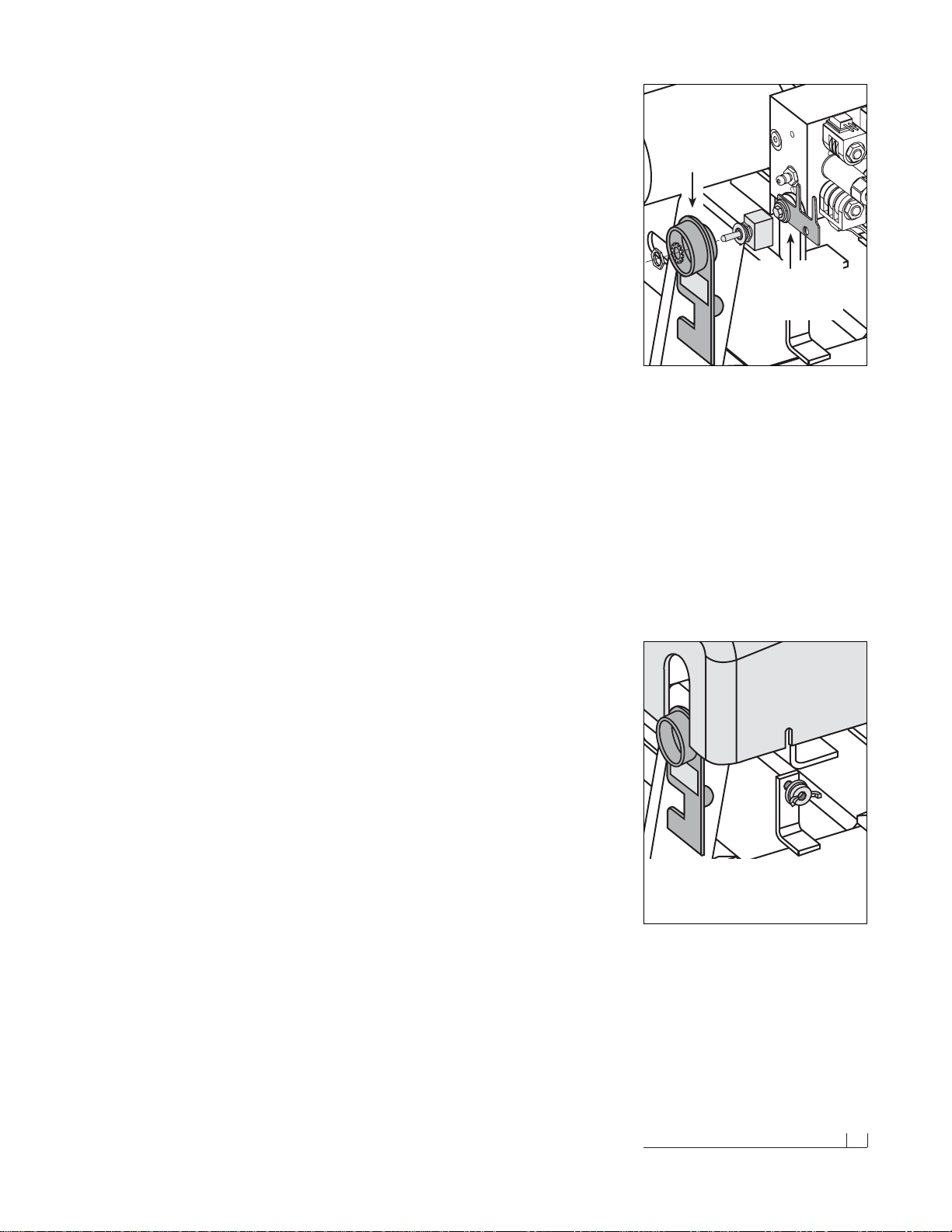
The kickstand is mounted to the side of the pivot
beam with one 1/2"-13 x 4-1/2" hex cap screw
and top lock nut. To pivot the kickstand, simply
pull the spring loaded leg out and rotate it until
the pin locks into place.The kickstand also has
an adjustable foot that can be moved to accommodate varying vehicle heights. The proper
height of your snowplow mounting points to level
ground should be set at 12-1/2".
Spring Loaded
Adjustable
Pivot Beam
Kickstand
12-1/2"
06 Moldboard & A-frame Assembly (cont.)
adapter on the cylinder.Both hoses should be routed through the triangular openings in the A-frame.
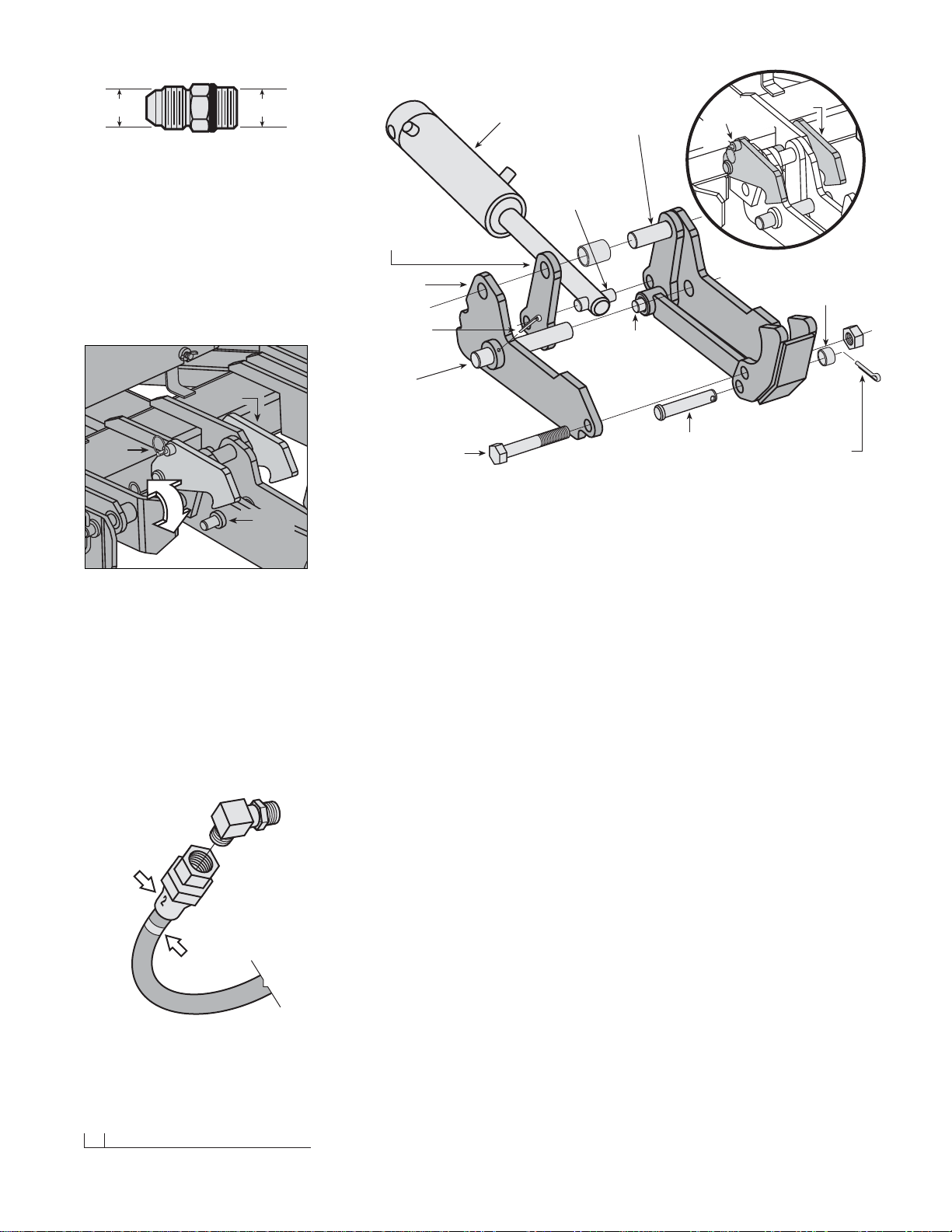
5. Begin the draw latch installation by first removing the DRAW LATCH
MOUNT PIN & SPACER from the assembly. By removing this pin, the
INNER DRAW LATCH PLATES can swing free.Proceed to remove
the INNER DRAW LATCH PLATE LIFT CYLINDER MOUNT PIN.
Position the plates on either side of the lift/lo w er cylinder rod and insert
the pin through the plates and cylinder rod.With the cylinder connected
to the inner draw latch plates, rotate the draw latch assembly toward
the draw latch mount holes on the A-frame.Align the holes in the outer
draw latch plate with those of the inner draw latch plates and the
A-frame. Note: The A-FRAME LATCH, located at the rear center of
the A-frame, should be raised up to insert the draw latch mount pin.
Pull the A-FRAME LATCH PULL PIN out and rotate the latch counterclockwise if it is locked into position.Secure the assembly to the A-frame
by replacing the draw latch mount pin and spacer.Reset the A-frame
latch so the A-frame latch pull pin locks into place.
Once you have completed the draw latch installation, we will shift our
attention to assembly of the manifold.The manifold, pump and coil harness
have been joined together at the factory; however, the manifold contains
several components that you will need to install prior to securing the
assembly to the A-frame.
6. Each of the 4 HOSE PORTS on the HYDRAULIC MANIFOLD are
covered with stretch wrap .Remove the wrap and install the appropriate
fitting (illustrated on page7) in its respective port.
Note: All por ts are identified by a stamped number on the manifold.
The numbers also identify the hydraulic functions, which can be referenced on the label under the hydraulic pump and manifold cover
(see illustration on page 7).
7/16" 7/16"
Male O.R.B.Connector Adapter
A-Frame
Latch Pull Pin
A-Frame
Latch
Outer Draw
Latch Plate
Inner Draw
Latch Plate
Draw Latch Mount Pin
(1" DIA. x 4-21/32") or
(1" DIA. x 3-7/8") for
700LD & 760LD only
Inner Draw Latch
Plate Lift Cylinder
Mount Pin
(3/4" DIA. x 2-1/2") or
(5/8" DIA. x 2-3/8") for
700LD & 760LD only
Draw Latch Arm
Pivot Pin
(3/4" DIA. x 2-1/2") or
(3/4" DIA. x 2-3/8") for
700LD & 760LD only
Hydraulic
Lift / Lower
Cylinder
Draw Pin
(1" DIA. x 6-1/2") or
(1" DIA. x 5-5/8") for
700LD & 760LD only
3/16" x 2-1/2"
Cotter Pin
Hex Head Cap Screw
(3/4"-10 x 4-1/2") or
(3/4"-10 x 4") for
700LD & 760LD only
1" O.D., 25/32" I.D. x 5/8"
Spacer
Clevis Pin
(3/4" x 3-41/64") or
(3/4" x 3-7/16") for
700LD & 760LD only
1/4" x 1-1/2"
Hammerlock
Cotter Pin
Draw Latch Assembly
The draw latch consists of a series of interconnected plates and pins that attach to the A-frame
and the hydraulic lift cylinder.
Draw
Pin
A-Frame
Latch
Lock Pin
A-Frame
Latch
To mount the straight blade, the A-frame latch
should be lowered over the draw pin– this allows
the draw latch to pull the plow into the undercarriage. Once the plow is safely attached to the
undercarriage, rotate the A-frame latch counterclockwise until the lock pin snaps into place.The
A-frame latch is only used to mount the plow.
Do not allow the lock pin to set behind the pin
catch hole in the raised position.The A-frame
latch should always be locked in place when
not in use.
Stamped
Number
Printed
Label
All of the hoses shipped with the snowplows
contain either a stamped number on the sleeve or
a printed label applied to the hose. All numbers,
stamped or printed, correspond with the stamping
of the ports on the manifold.
Moldboard & A-frame Assembly (cont.) 07
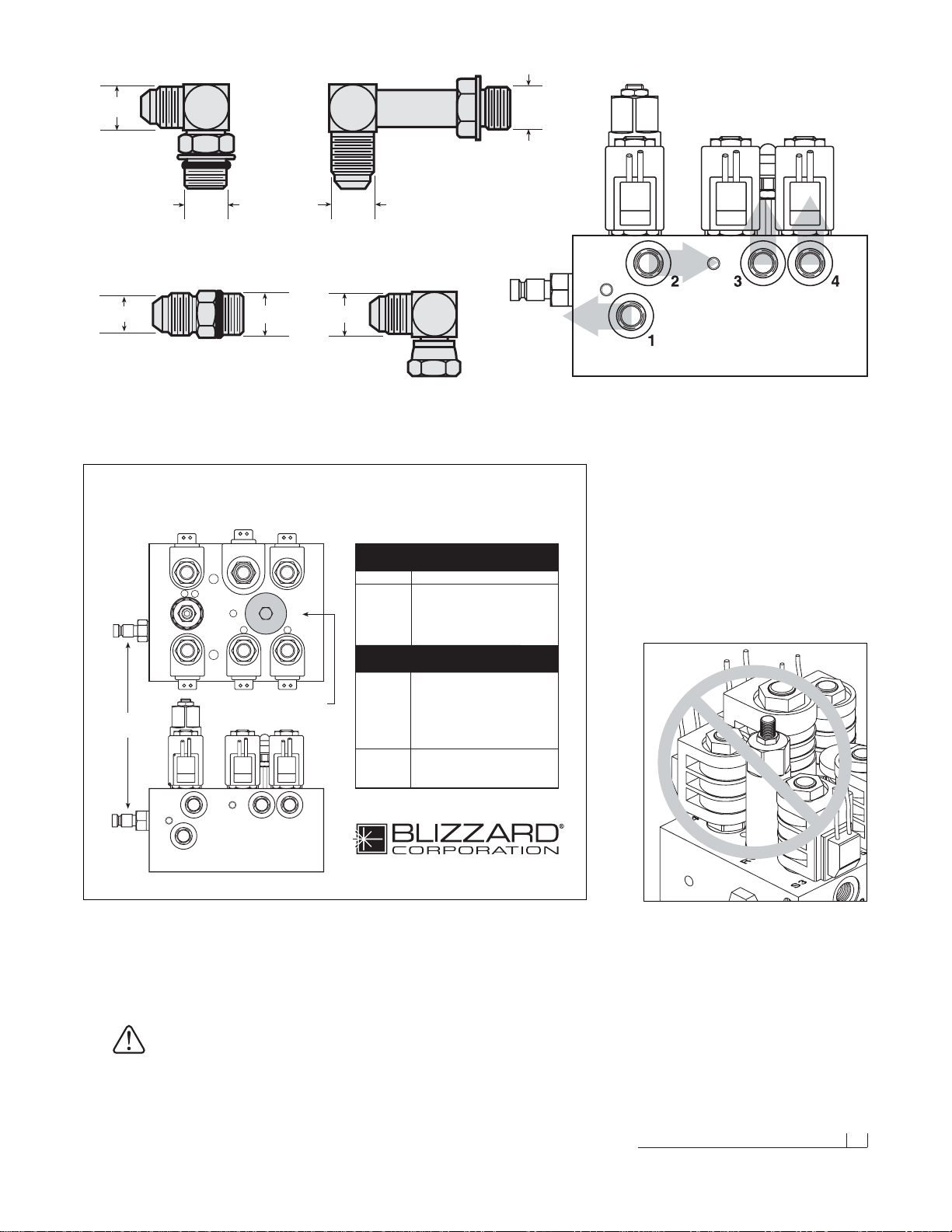
Installing The Manifold Adapters
There are a total of 6 hydraulic adapters to install.
All of the adapters can be found packaged with
the manifold assembly. Remove the protective
stretch wrap from the manifold in a clean area.
DO NOT let any foreign objects enter into the
open ports.The valves can become contaminated
and greatly hinder the plow’s performance.
Review the table on page 33 for proper torque
specifications.
7/16" 9/16"
7/16"
9/16"
9/16"
9/16"
9/16"
Male O.R.B.Connector Adapter & 90˚ Swivel Elbow Adapter
(Ports #3 & #4)
90˚ Adjustable Elbow O.R.B.Adapter
(Port #1)
Male Extra Long Elbow Adapter
(Port #2)
S6 S8S4
RV FC
S3 S5 S7
Hydraulic Hose Identification Guide
Straight Blade Snowplows
Calumet, Michigan 49913
HYDRAULIC HOSES
1
23 4
Port Function
S3 Left Angle - Right Cylinder
S4 Right Angle - Left Cylinder
S6 & S7 Raise - Lift Cylinder (Base)
S5 & S8 Lower - Lift Cylinder (Rod)
S5 & S7 Float
RV Angle Relief Valve
FC Variable Flow Control Valve
BLZ 1035
NOTE: Energize the following
solenoids for the functions:
1Right Angle - Left Cylinder
2 Left Angle - Right Cylinder
3Raise - Lift Cylinder (Base)
4Lower - Lift Cylinder (Rod)
Pressure Gauge
Quick Connect
Clockwise - Decreases Plow Drop Speed
Counterclockwise - Increases Plow Drop Speed
Note: The gray arrows shown on the manifold illustration above indicate
the direction the 90˚ adapters should face to receive the hydraulic hoses.
7. Next, align the mount holes in the pump with the holes in the hinged
bracket, located on the A-frame .Note:To help facilitate the pump mount,
first angle the hinged bracket as needed and tighten the bracket
hardware, locking it in place.
CAUTION:When installing the manifold between the mount
brackets on the A-frame, hold the manifold at the sides of
the block.Never handle the manifold b y the wire lead coils.
Doing so can cause a solenoid cartridge to bend, causing
the cartridge to stick when activated.
When installing the manifold between the mount
brackets on the A-frame, DONOT handle the
manifold by the wire lead coils.The solenoid
cartridges can bend, causing them to stick when
activated.Always carry the manifold by the sides
of the aluminum block.
08 Moldboard & A-frame Assembly (cont.)
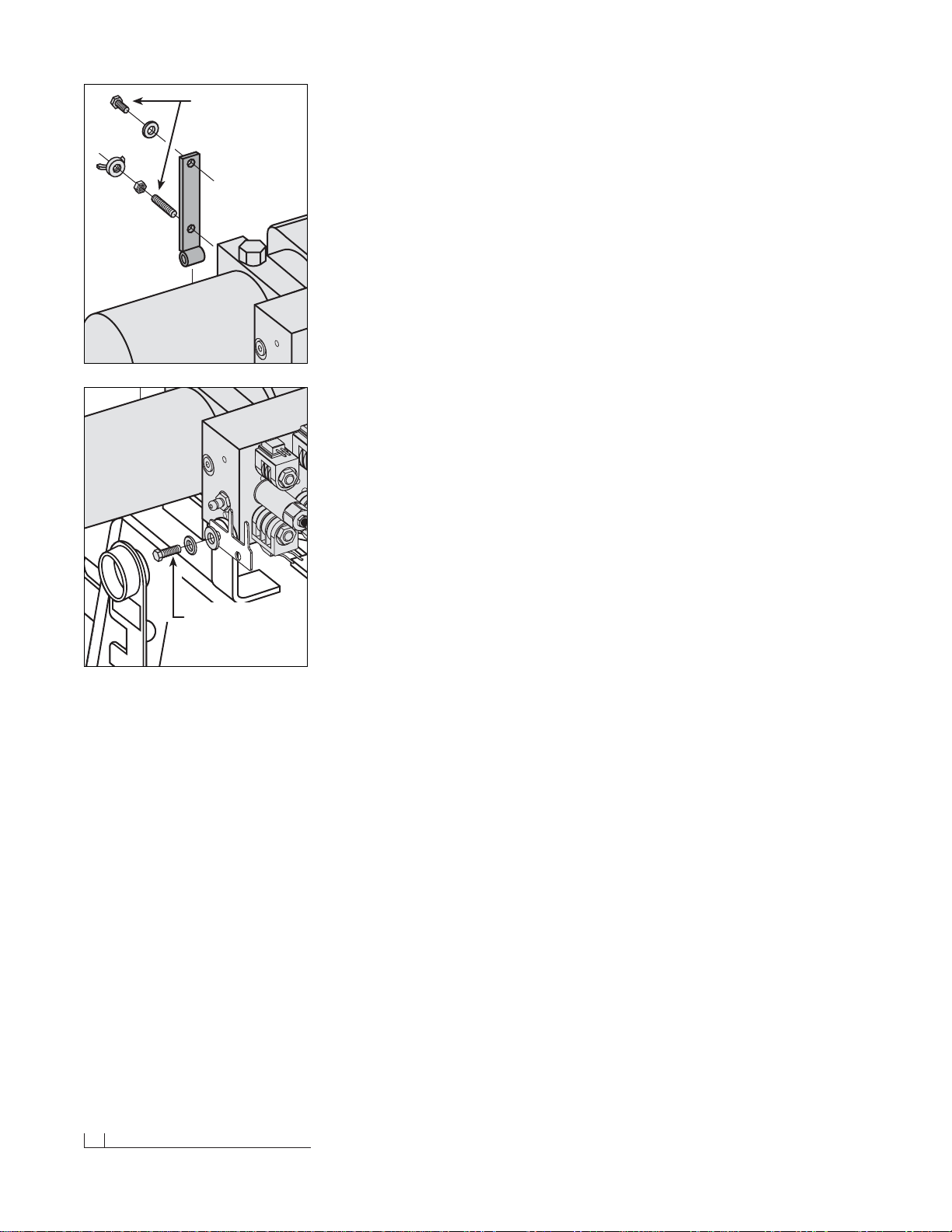
Secure one 3/8"-16 x 3/4" hex head cap screw and 3/8" flat washer
through the top mount hole in the bracket and into the pump. Insert
one 3/8"-16 x 1-3/4" threaded stud and 3/8"-16 jam nylon insert lock
nut through the bottom mount hole in the bracket and into the pump.
The threaded stud should bottom out in the pump.Note:A medium
strength threadlocker , such as Loctite®242® should be used on both
of the pump mount fasteners.This will help prev ent the fasteners from
working free.
8. Once the pump and manifold assembly is in place, connect the
hydraulic hoses to their respectiv e adapters on the manifold. Remember,
the labeling on the hydraulic hoses correspond with the stamped
numbers on the manifold.
Begin installing the hoses with the driver’s side r aise cylinder hose (#3).
Attach the straight end of the hose to the 7/16"-20 x 9/16"-18 90˚
swivel elbow adapter on the manifold. Connect the passenger’s side
lower cylinder hose to Port #4. Loop the hose through the opening in
the A-frame and connect the straight end of the hose to the 7/16"-20
90˚ swivel elbow adapter. Run both angle cylinder hoses (#1 and #2)
over the A-frame angle and to their respective manifold por ts. Note:
The lift cylinder hoses should be routed through the triangular openings
in the A-frame.
9. Next, secure the manifold to the A-fr ame.Remove both 3/8" flat washers,
3/8" split lock washers and 3/8"-16 x 1" hex head cap scre ws from the
manifold and align the mount holes with the A-frame brac kets .Position
the DIODE PACK MOUNT BRACKET against the outside of the Aframe bracket on the driv er’s side. Note: Both of the prongs should be
facing up.Align the outside hole on the diode bracket with the holes
on the A-frame and manifold.Properly replace and tighten all hardware.
Note:A medium strength threadlocker, such as Loctite®242® should
be used to secure the manifold mount fasteners.
10. Hook each EXTENSION SPRING to the receiving holes located on
the pivot beam and connect the opposite end of the spring to their
respective SPADE BOLTS.Install the 5/8"-11 x 5" spade bolts through
the EXTENSION SPRING MOUNTING ANGLE on the top rear of the
blade.Secure each spade bolt by placing one 5/8" flat washer on the
bolt and thread one 5/8"-11 nylon insert lock nut.Tighten each lock nut
until a piece of paper can pass between the 3th & 4th coils on the spring.
11. Install the flexible BLADE GUIDES at each end of the moldboard.
Insert the 5/16"-18 x 1" hex head cap screw through the holes provided
at the top of the outside reinforcement rib.Tighten all screws using the
nylon insert lock nuts provided.
Congratulations! You have successfully completed half of the installation.
Don’t quit now, you’re nearly out of the garage!
A medium strength threadlocker, such as Loctite®
242®, should be used to properly secure the
mount hardware for the pump and manifold. This
will help prevent the hardware from working free
from vibration and plow use. Apply a liberal
amount of threadlocker to both threaded fasteners and the threads in the pump (top diagram).
The manifold receives two 3/8"-16 x 1" hex cap
screws—one on each side of the A-frame. Likewise, use threadlocker on these fasteners and
the tapped holes in the manifold (bottom diagram).
Use Loctite® on
Manifold Mount
Hardware
Apply Loctite®
To Pump Mount
Hardware Upon
Installation
Electrical Assembly - Plow Harness 09
Electrical Assembly - Plow Harness
1. Begin the electrical assembly by connecting the RED POWER WIRE
from the PLOW ELECTRICAL HARNESS to the PUMP motor terminal
stud using the hardware provided on the pump.
2. Place one 3/8" INTERNAL/EXTERNAL TOOTH LOCK WASHER, the
BLACK GROUND WIRE (from the harness) and the RED GROUND
WIRE on the COIL WIRE HARNESS (from the manifold) over the
tapped hole on the pump and secure the ground using one 3/8"-16 x
3/4" hex head cap screw.
3. Remove the hex jam nut and external tooth lock washer from the
POWER HITCH CONNECT/DISCONNECT TOGGLE SWITCH and
insert it through the back of the mounting bracket on the A-frame.Align
the notch in the key washer on the switch to the notch on the bracket.
Replace the lock washer and jam nut and tighten until the switch is
firmly in place. Next, attach the connector on the plow harness to the
switch. Note: Use caution when making the connection.Switches can
break if done forcefully.
4. Continue the harness installation by connecting the PLASTIC FEMALE
ELECTRICAL CONNECTOR on the harness to the PLASTIC MALE
ELECTRICAL CONNECTOR found on the coil wire har ness.
5. Finalize the harness installation by sliding the DIODE PACK over the
diode pack mount brack et located behind the connect/disconnect toggle
switch. Position the wire har ness braid in the notch on the switch
bracket and secure it with a cable tie.The diode pack mount bracket
contains an extra hole f or a cable tie. Use it to secure the diode pack.
6. To install the PUMP & MANIFOLD COVER, align the notches in the
cover with the welded bolts on the A-frame br ack ets.Secure the cover
with two 3/8" FLANGED WING NUTS. Verify the cover is positioned
over the protective toggle switch hood.Pop the front of the cover on
the threaded stud and secure it with the remaining wing nut.
Congratulations! You have just completed building the finest snowplow
available! However, the vehicle wire harness still needs to be installed.
That is the focus of the second half of the electrical assembly instruction.
Diode Pack
Mount Bracket
Draw Latch
Toggle Switch
Mount Bracket
The diode pack (on the plow harness) clips onto
the diode pack mount bracket.Place a cable tie
through the hole at the end of the bracket and
over the pack to secure it in place.
The draw latch toggle switch installs through the
rear of the bracket with the protective hood.Align
the key washer with the slot cut in the bracket to
prevent the switch from turning. Secure the
switch with the hardware provided.Note: Use the
square notch in the bracket (below the protective
hood) to position the braided harness.Use another
cable tie to hold the harness against the bracket.
The Pump Cover Installs Over
The Top Of The Draw Latch
Switch Bracket
To properly secure the pump and manifold cover
on the A-frame, position the cover over the top of
the protective hood on the draw latch switch
mount bracket. Align the slots in the cover with
the welded bolts on the A-frame brackets—
secure the cover using three flanged wing nuts.
10 Electrical Assembly - Vehicle Harness
Electrical Assembly - Vehicle Harness
CAUTION:Alwa ys perf orm the vehic le wire harness assembly with the vehicle off and the keys out of the ignition. Use
caution when testing the electrical wires for the vehicle’s
headlight functions.
1. Begin the installation of the electrical har ness under the hood. Insert
the WHITE POWER CONNECTOR & RED POWER WIRE (with FUSE)
end of the harness through the driver’s side fire wall access panel into
the vehicle cab.Note:You may need to widen an opening or cut access
to the cab interior to facilitate the assembly. Loosely position the
remaining portion of the harness over the driver’s side fender w ell and
place the MOLDED RUBBER POWER CONNECTOR near the bumper .
2. Next, attach the POWER CONTACTOR (SOLENOID) to the driver’s
side wheel well or engine fan guard using two 12-14 x 3/4" hex washer
self-drilling screws.Note: Some model vehicles provide mounting
locations for accessory components.Connect the 24" BLACK GROUND
WIRE to either small terminal on the solenoid and attach the opposite
end to the vehicle with one hex washer self-dr illing screw. Locate the
BROWN/WHITE PUMP SOLENOID ACTIVATION WIRE on the wire
harness and position the eyelet over the remaining small terminal on
the contactor.Secure it with the hardware provided on the solenoid.
3. Proceed to connect the BLACK VEHICLE WIRE HARNESS GROUND
WIRE to the negative terminal on the vehicle’ s battery.Cut the wire to
length and crimp a 3/8" DIA. END RING TERMINAL on the wire.It is
also recommended that the ring terminal be soldered. Note: The har-
ness should be secured to the vehicle prior to taking the necessary
measurement. Measure the distance needed for the RED POWER
WIRE to reach the solenoid and properly secure an end ring terminal
to it. Connect the power wire to either large terminal on the solenoid.
CAUTION:Do not fasten the wire harness to areas that come
in contact with moving engine parts or possess extreme
heat.The harness could become tangled and/or melt causing
electrical failure and vehicle damage.
4. Attach and solder an end ring ter minal to both ends of the remaining
length of the red 4 gauge wire. Connect one end of the wire to the
open terminal on the solenoid and the remaining end to the positive
terminal on the battery.
5. With the vehicle harness secured to the truck, position the MAIN
LIGHTING HARNESS such that both of the large, gray VEHICLE
HEADLIGHT CONNECTORS are near the truck headlights and the
smaller, black PLOW HEADLIGHT CONNECTORS are near the grill
of the vehicle.
6. Plug the 9 TERMINALS, from the main lighting har ness, into the
HEADLIGHT RELAY. See the illustration to the left. Connect the
GREEN & YELLOW wire, from the vehicle harness with the molded
power plug, to the remaining spade on the relay. Securely mount the
relay to the vehicle with the terminals facing down. Installing the relay
in this position will allow moisture to drain from the relay.
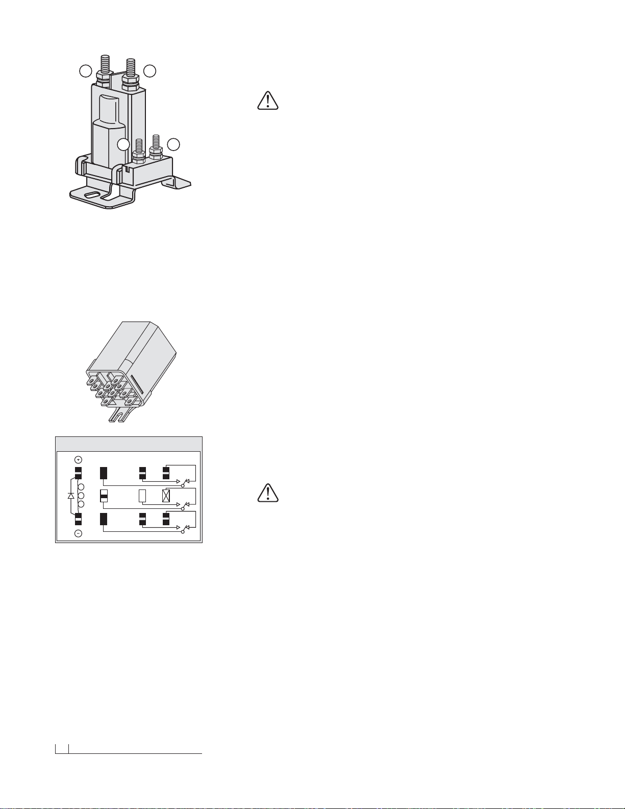
A B
C D
Heavy-Duty Power Contactor (Solenoid)
There are four wires that need to be attached to
the power contactor:
(A) Red Power Battery Wire
(B) Vehicle Wire Harness Red Power Wire
(C) 24" Black Ground Wire
(D) Brown/White Pump Solenoid Activation Wire
A
B
G/Y
BK/W
Y7
W/R 8
LT. G 9
HIGH
GROUND
LOW
Y/B 4
WHITE 5
Y/R 1
N/A 2
LT. G/B 6
LT. G/R
3
3PDT RELAY (30 AMPS) 12 VOLTS
Connect the color coded wires from the vehicle
harness to the headlight relay shown above.The
wires correspond to the numbers/letters on the
relay or the color abbreviations on the illustration.
(A) BK/W = Black/White Wire
(B) G/Y= Green/Yellow Wire
(1) Y/R = Yellow/Red Wire
(2) N/A = Not Applicable
(3) LT.G/R = Light Green/Red Wire
(4) Y/B = Yellow/Black
(5) W = White
(6) LT.G/B = Light Green/Black
(7) Y = Yellow
(8) W/R = White/Red Wire
(9) LT. G= Light Green
 Loading...