

Page 1
240Z WASH
Blizzard Lighting, LLC
http://www.blizzardpro.com
Waukesha, WI USA
Copyright (c) 2019
Page 2

TABLE OF CONTENTS
Redstone™ 240Z Wash LED Moving Head 1
1. Getting Started 3
What’s In The Box? 3
Getting It Out Of The Box 3
Powering Up! 3
Getting A Hold Of Us 3
Safety Instructions (Don’t Stick Your Hand In The Toaster!) 4
2. Meet Redstone™ 240Z Wash 5
Main Features 5
DMX Quick Reference 5
The Redstone™ 240Z Wash Pin-up Picture 6
3. Setup 7
Connecting A Bunch Of Redstone™ 240Z Wash Fixtures 7
Data/DMX Cables 7
Using The Built-in W-DMX™ 7
Cable Connectors 8
3-Pin??? 5-Pin??? Huh? 8
Take It To The Next Level: Setting up DMX Control 8
Fixture Linking (Master/Slave Mode) 9
Clamp Mounting 9
Securing the Fixture 9
4. Operating Adjustments 10
The Control Panel 10
Control Panel Menu Structure 11
DMX Mode 12
Set the Starting DMX Address 12
Select the DMX Channel Mode 12
Signal Selection 12
Auto Mode 12
Sound Active Mode 12
Pan/Tilt Inverse 12
PT Feedback 12
White Balance 12
Dimmer Curves 13
Display Inverse 13
Backlight Switch 13
Backlight Intensity 13
Language 13
Test Modes 13
Calibration 13
DMX Values In-Depth 14
5. Appendix 16
A Quick DMX Lesson 16
Keeping Your Redstone™ 240Z Wash As Good As New 17
Returns (Gasp!) 17
Shipping Issues 17
Tech Specs 18
Troubleshooting 18
Dimensional Drawings 19
Photometric Data 18
Redstone™ 240Z Wash Manual - Rev. A (c) 2019 Blizzard Lighting, LLC
Page 2
Page 3

1. GETTING STARTED
What’s In The Box?
• 1 x Redstone™ 240Z Wash
• 1 x Ever-So-Handy Power Cord
• 1 x DMX Signal Cable
• 2 x Mounting Bracket
• 1 x Safety Cable
• This Lovely User Manual
Getting It Out Of The Box
Congratulations on your purchase of the Redstone™ 240Z Wash xture, you're a go for
launch! So now that you’ve got your 240Z (or hopefully 240Zs)
unpack the box and check the contents to ensure that all parts are present and in good
condition. If anything looks as if it has been damaged in transit, notify the shipper immediately and keep the packing material for inspection. Again, please save the carton and
all packing materials. If a xture must be returned to the factory, it is important that the
xture be returned in the original factory box and packing.
Powering Up!
All xtures must be powered directly o a switched circuit and cannot be run o a
rheostat (variable resistor) or dimmer circuit, even if the rheostat or dimmer
channel is used solely for a 0% to 100% switch.
AC Voltage Switch - Not all xtures have a voltage select switch, so please verify that the
xture you receive is suitable for your local power supply. See the label on the xture or
refer to the xture’s specications chart for more information. A xture’s listed current
rating is its average current draw under normal conditions. Check the xture or device
carefully to make sure that if a voltage selection switch exists that it is set to the correct
line voltage you will use.
Warning! Verify that the voltage select switch on your unit matches the line
voltage applied. Damage to your xture may result if the line voltage applied does
not match the voltage indicated on the voltage selector switch. All xtures must
be connected to circuits with a suitable Ground (Earthing).
, you should carefully
Getting A Hold Of Us
If something is wrong, please just visit our website at www.blizzardpro.com/
support and open a support ticket. We’ll be happy to help, honest.
Disclaimer: The information and specications contained in this document are subject
to change without notice. Blizzard Lighting™ assumes no responsibility or liability for any
errors or omissions that may appear in this user manual. Blizzard Lighting™ reserves the
right to update the existing document or to create a new document to correct any errors
or omissions at any time. You can download the latest version of this document from www.
blizzardpro.com.
Author: Date: Last Edited: Date:
J. Thomas 4/4/2019 J. Thomas 4/4/2019
Redstone™ 240Z Wash Manual - Rev. A (c) 2019 Blizzard Lighting, LLC
Page 3
Page 4
SAFETY INSTRUCTIONS
Please read these instructions carefully. They include
important information about the installation, usage and
• Please keep this User Guide for future use. If you sell the unit to someone
else, be sure that they also receive this User Guide.
• ALWAYS make sure that you are connecting to the proper voltage, and that
the line voltage you are connecting to is not higher than that stated on the de-
cal or rear panel of the xture.
• This product is intended for indoor use only.
• To prevent risk of re or shock, do not expose xture to rain or moisture.
• Make sure there are no ammable materials close to the unit while operating.
• The unit must be installed in a location with adequate ventilation, at least
20in (50cm) from adjacent surfaces. Be sure that no ventilation slots are
blocked.
• ALWAYS disconnect from the power source before servicing or replacing fuse
and be sure to replace with same fuse size and type.
maintenance of this product.
• ALWAYS secure xture using a safety chain. NEVER carry the xture by its
head. Use its carrying handles.
• DO NOT operate at ambient temperatures higher than 104°F (40°C).
• In the event of a serious operating problem, stop using the unit immediately.
NEVER try to repair the unit by yourself. Repairs carried out by unskilled people
can lead to damage or malfunction. Please contact the nearest authorized technical assistance center. Always use the same type spare parts.
• NEVER connect the device to a dimmer pack.
• Make sure the power cord is never crimped or damaged.
• Never disconnect the power cord by pulling or tugging on the cord.
• Avoid direct eye exposure to the light source while it is on.
Caution! There are no user serviceable parts inside the unit. Do not
open the housing or attempt any repairs yourself. In the unlikely event
your unit may require service, please open a support ticket at www.
blizzardpro.com/support.
Redstone™ 240Z Wash Manual - Rev. A (c) 2019 Blizzard Lighting, LLC
Page 4
Page 5
2. MEET REDSTONE™ 240Z WASH
MAIN FEATURES
• 1x 240W OSRAM 4-IN-1 RGBW LED
• 5°-70° smooth and quiet linear motorized zoom
• Highly ecient Fresnel lens, integrated w/light pipe technology
• Built-in Wireless Solutions™ W-DMX receiver
• Even, soft edge and pure color mixing coverage
• Flicker free operation for broadcast TV and lm
• 540°/270° PAN and TILT + invert and calibration
• 4x user selectable dimming curves
• 1-25Hz fps strobe + random/pulse eects
• Multiple pre-programmed macro eects with variable speed
• Rotating prism beam shaping eects
• Ecient low noise self-adjusting fan cooling system
• 3-pin DMX In/Out + RJ45 etherCON In/Out (Art-NET)
• PowerCON® compatible AC power In/Out
• 2.4-inch TFT LCD display menu with 4 button control panel
• 18/21/28 DMX channel modes
• DMX512, Art-Net, RDM, M/S, sound active & auto mode
DMX Quick Reference (21/18/28-Channel Modes)
Ch. 21-Channel Ch. 18-Channel Ch. 28-Channel
1 Pan 1 Pan 1 Pan
2 Fine Pan (16-bit) 2 Tilt 2 Fine Pan (16-bit)
3 Tilt 3 Pan/Tilt Speed 3 Tilt
4 Fine Tilt (16-bit) 4 Red Intensity 4 Fine Tilt (16-bit)
5 Pan/Tilt Speed 5 Green Intensity 5 Pan/Tilt Speed
6 Red Intensity 6 Blue Intensity 6 Red Intensity
7 Green Intensity 7 White Intensity 7 Red Intensity Fine
8 Blue Intensity 8 Strobe 8 Green Intensity
9 White Intensity 9 Dimmer 9 Green Intensity Fine
10 Strobe 10 CTO 10 Blue Intensity
11 Dimmer 11 Color Macros 11 Blue Intensity Fine
12 Dimmer Fine 12 Color Presets 12 White Intensity
13 CTO 13 Color Preset Dimmer 13 White Intensity Fine
14 Color Macros 14 Focus 14 Strobe
15 Color Presets 15 Beam Shaper (Prism) 15 Dimmer
16 Color Preset Dimmer 16 Beam Shaper Rotation 16 Dimmer Fine
17 Focus 17 Zoom 17 CTO
18 Beam Shaper (Prism) 18 Special Function 18 Color Macros
19 Beam Shaper Rotation -- -- 19 Color Presets
20 Zoom -- -- 20 Color Preset Dimmer
21 Special Function -- -- 21 Focus
-- -- -- -- 22 Focus Fine
-- -- -- -- 23 Beam Shaper (Prism)
-- -- -- -- 24 Beam Shaper Rotation
-- -- -- -- 25 Indexing Fine
-- -- -- -- 26 Zoom
-- -- -- -- 27 Zoom Fine
-- -- -- -- 28 Special Function
Redstone™ 240Z Wash Manual - Rev. A (c) 2019 Blizzard Lighting, LLC
Page 5
Page 6
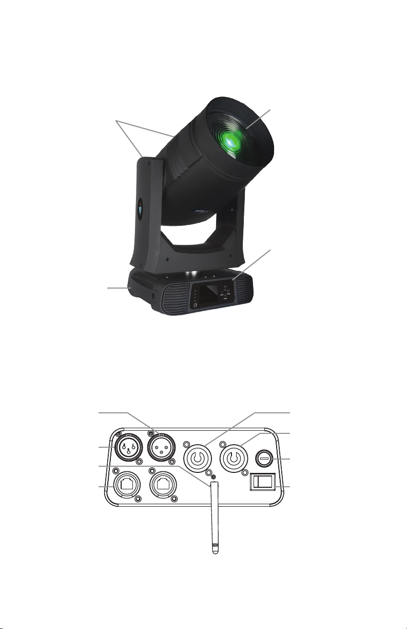
Figure 1: Redstone™ 240Z Wash Pin-Up Picture
Fuse
Figure 1: Redstone™ 240Z Wash Pin-Up Picture
Head/Arms
Carry
Handle
240W OSRAM
RGBW LED
Light Source
4-Button
Control Panel
with 2.4" TFT
Color Display
Figure 2: The Rear Connections
DMX Out Power In
DMX In
Antenna
Art-Net
Redstone™ 240Z Wash Manual - Rev. A (c) 2019 Blizzard Lighting, LLC
Page 6
Page 7

3. SETUP3. SETUP
Connecting A Bunch of Redstone™ 240Z Wash Fixtures
You will need a serial data link to run light shows using a DMX-512 controller or to run
shows on two or more xtures set to sync in master/slave operating mode. The combined
number of channels required by all the xtures on a serial data link determines the number
of xtures the data link can support.
Fixtures on a serial data link must be daisy chained in one single line. Also, connecting
more than 32 xtures on one serial data link without the use of a DMX optically-isolated
splitter may result in deterioration of the digital DMX signal. The maximum recommended
cable-run distance is 500 meters (1640 ft). The maximum recommended number of
xtures on a serial data link is 32 xtures.
Data/DMX Cabling
To link xtures together you’ll need data cables. You should use data-grade cables that can
carry a high quality signal and are less prone to electromagnetic interference. The cables
should have the following characteristics:
• 2-conductor twisted pair plus a shield
• Maximum capacitance between conductors – 30 pF/ft.
• Maximum capacitance between conductor & shield – 55 pF/ft.
• Maximum resistance of 20 ohms / 1000 ft.
• Nominal impedance 100 – 140 ohms
Using The Built-in W-DMX™
To use the built-in W-DMX™ receiver, you will rst need a W-DMX™ transmitter to
broadcast the signal, such as our own LightCaster™ W-DMX™ transceiver. Paired up with a
LightCaster™ W-DMX™ transceiver, you can expect an outstanding wireless range of up to
500 meters (line-of-sight).
If you’re using an external wireless W-DMX transmitter like our LightCaster™ W-DMX™
transceiver, power it up and plug it into the “DMX OUT” connector of the controller.
* Please refer to your W-DMX™ transmitter user manual for more product specic instructions.
1. One transceiver with multiple receivers:
a.) Power on all units, and verify that your transmitter is transmitting a signal.
b.) On the receiving W-DMX xtures, use the control panel menu to navigate to DMX
> Connect to, then highlight Wireless Only (wireless will also work as a secondary
connection method under the XLR Priority menu selection if an XLR signal is lost.)
c.) Press and hold down the <ENTER> button to sync the xtures.
2. Multiple transceivers, multiple receivers; e.g. 3 groups consisting of a transceiver &
receiver(s) named A, B, and C:
1.) Turn power o of all units.
2.) Group “A” gets powered on, then follow step 1 above.
3.) Group “B” gets powered on, then follow step 1 above.
4.) Group “C” gets powered on, then follow step 1 above.
Redstone™ 240Z Wash Manual - Rev. A (c) 2019 Blizzard Lighting, LLC
Page 7
Page 8

Cable Connectors
Cables must have a male XLR connector on one end and a female XLR connector on the
other end. (Duh!)
CAUTION: Do not allow contact between the common and the xture’s chassis
ground. Grounding the common can cause a ground loop, and your xture may
perform erratically. Test cables with an ohm meter to verify correct polarity and
to make sure the pins are not grounded or shorted to the shield or each other.
3-Pin??? 5-Pin??? Huh?!?
If you use a controller with a 5 pin DMX output connector, you will need to use a 5 pin to 3 pin adapter.
They are widely available over the internet and from specialty retailers If you’d like to build your own, the
chart below details a proper cable conversion:
Conductor 3-Pin Female (Output) 5-Pin Male (Input)
Ground/Shield Pin 1 Pin 1
Data 1- (Primary Data Link) Pin 2 Pin 2
Data 1+ (Primary Data Link) Pin 3 Pin 3
Data 2- (Optional Secondary Data Link) Pin 4 Pin 4
Data 2+ (Optional Secondary Data Link) Pin 5 Pin 5
Take It To The Next Level: Setting Up DMX Control
Step 1: Connect the male connector of the DMX cable to the female connector (output) on
the controller.
Step 2: Connect the female connector of the
DMX cable to the rst xture’s male connector
(input). Note: It doesn’t matter which
xture address is the rst one connected. We
recommend connecting the xtures in terms
of their proximity to the controller, rather than
connecting the lowest xture number rst, and
so on.
Step 3: Connect other xtures in the chain
from output to input as above. Place a DMX
terminator on the output of the nal xture to
ensure best communication.
Redstone™ 240Z Wash Manual - Rev. A (c) 2019 Blizzard Lighting, LLC
Page 8
Page 9

Fixture Linking (Master/Slave Mode)
1. Connect the (male) 3-pin connector side of the DMX cable to the output (female)
3-pin connector of the rst xture.
2. Connect the end of the cable coming from the rst xture which will have a (female)
3-pin connector to the input connector of the next xture consisting of a (male) 3-pin
connector. Then, proceed to connect from the output as stated above to the input of
the following xture and so on.
Clamp Mounting
This xture provides a mounting bracket assembly that secures the bottom of the base, the
“Omega Brackets,” and the safety cable rigging point together. When mounting this xture
to truss, be sure to secure an appropriately rated clamp to the omega bracket using an
M10 screw tted through the center hole of the “omega bracket”.
3
1
1.) Clamp
2.) Omega Bracket
3.) Safety Cable
4.) ¼ Turn Quick Locks
2
4
1/4 Tu rn 1/4 Turn
Securing the Fixture
Regardless of the rigging option you choose for your xtures always be sure to secure
your xture with a safety cable. Be sure to only use the designated rigging point found on
the underside of the base assembly for the safety cable. Never secure a safety cable to a
carrying handle.
Redstone™ 240Z Wash Manual - Rev. A (c) 2019 Blizzard Lighting, LLC
Page 9
Page 10

4. OPERATING ADJUSTMENTS
The Control Panel
All the goodies and dierent modes possible with the Redstone 240Z
Wash are accessed by using the control panel on the front of the x-
ture. There are 4 control buttons to the right of the LCD display which
allow you to navigate through the various control panel menus.
<MENU>
Is used to navigate to the previous higher-level menu item.
<ENTER>
Is used to select and conrm/store the current selection.
<UP>
Scrolls through menu items and numbers in ascending order.
<DOWN>
Scrolls through menu items and numbers in descending order.
DMX Address Led 29°C
MasterSlave Mode 21Ch.
The control panel display shows the menu items you select from the
menu map on page #11. When a menu function is selected, the dis-
play will show immediately the rst available option for the selected
menu function. To select a menu item, press <ENTER>.
Use the <UP> and <DOWN> buttons to navigate the menu options.
Press the <ENTER> button to select the menu function currently displayed, or to enable a menu option. To return to the previous option or
menu without changing the value, press the <MENU> button.
Redstone™ 240Z Wash Manual - Rev. A (c) 2019 Blizzard Lighting, LLC
Page 10
Page 11

Control Panel Menu Structure
DMX DMX Address Set the starting address (001-512)
DMX Channel Mode Mode 1 (21), 21-channel mode
Mode 2 (18), 18-channel mode
Mode 3 (28), 28-channel mode
Loss of DMX M/S Mode
Hold
Blackout
Connect to XLR Priority
Wireless Priority
XLR Only
Wireless Only
ArtNet Only
Retransmit Retransmit DMX output (No/Yes), no = terminate
Un-Link Wireless Disconnect existing wireless connection (No/Yes)
Ethernet IP Settings IP Address
Subnet Mask
Artnet Settings Universe (000-255)
View DMX Value View current DMX values
SHOW Auto Mode Auto 1
Auto 2
Auto 3
Auto 4
Sound Active Sound Active Mode (O/On)
Mic Sensitivity Adjust the mic sensitivity level from 0-100
SET Pan Inverse No/Yes
Tilt Inverse No/Yes
P/T Feedback No/Yes (pan/tilt autocorrect position)
White Balance R/G/B adjustments (000-255)
Dimmer Curve Linear
Square Law
Inv SQ Law
S Curve
DISP Display Inverse Flip the menu display (O/On)
Backlight Switch Display: On=shuts o after 1m, O=always on
Backlight Intensity Display brightness setting (1-10)
Language English
Chinese
TEST Auto Test Auto testing mode
Manual Test Manually adjust any individual DMX channel
INFO Fixture Use Time Display total runtime hours
Firmware Version Display all current rmware versions
REST Pan/Tilt Restore default pan/tilt settings
Eect Restore default eect settings
All Restore default pan/tilt and eect settings
SPEC. Factory Setting Reset all factory default settings
Redstone™ 240Z Wash Manual - Rev. A (c) 2019 Blizzard Lighting, LLC
Page 11
Page 12

DMX Mode
Allows the unit to be controlled by any universal DMX controller.
Set the Starting DMX Address:
1.) Navigate the menu until you reach DMX, and press <ENTER>.
2.) Highlight DMX Address, and press <ENTER>.
3.) Use the <UP/DOWN> buttons to select a channel from 001-512.
4.) Press the <ENTER> button to conrm.
Select the DMX Channel Mode:
1.) Navigate the menu until you reach DMX, and press <ENTER>.
2.) Highlight DMX Channel Mode, and press <ENTER>.
3.) Use the <UP/DOWN> buttons to select 21, 18, or 28-channel mode.
4.) Press the <ENTER> button to conrm.
Signal Selection:
1.) Navigate the menu until you reach DMX, and press <ENTER>.
2.) Highlight Connect to, and press <ENTER>.
3.) Use the <UP/DOWN> buttons to highlight either XLR Priority, Wireless Priority,
XLR Only, Wireless Only, or ArtNet Only, and press <ENTER>.
Auto & Sound Active Modes
Allows a single or Master/Slaved units to run factory installed programs at user selectable speeds.
Auto Mode:
1.) Navigate the menu until you reach SHOW, and press <ENTER>.
2.) Use the <UP/DOWN> buttons to highlight any available Auto mode.
3.) Press the <ENTER> button to conrm your selection.
4.) Ensure that DMX > Loss of DMX is set to M/S Mode.
Sound Active Mode:
1.) Navigate the menu until you reach SHOW, and press <ENTER>.
2.) Use the <UP/DOWN> buttons to highlight Sound Active.
3.) Press <ENTER>, highlight ON, then press the <ENTER> button to conrm.
4.) For mic sensitivity, highlight Mic Sensitivity, and press <ENTER>.
5.) Adjust the mic sensitivity from 0-100, and press <ENTER>.
Setup Options
The setup menu contains a variety of user congurable xture settings.
Pan/Tilt Inverse:
1.) Navigate the menu until you reach SET, and press <ENTER>.
2.) Now highlight Pan Inverse or Tilt Inverse, and press <ENTER>.
3.) To activate, use the <UP/DOWN> buttons to highlight Yes, and press <ENTER>.
PT Feedback:
1.) Navigate the menu until you reach SET, and press <ENTER>.
2.) Then navigate to P/T Feedback and press <ENTER>.
3.) Use the <UP/DOWN> buttons to highlight No or Yes, and press <ENTER>.
White Balance:
1.) Navigate the menu until you reach SET, and press <ENTER>.
2.) Then navigate to White Balance and press <ENTER>.
3.) From here, you can adjust the individual R/G/B levels from 000-255.
Redstone™ 240Z Wash Manual - Rev. A (c) 2019 Blizzard Lighting, LLC
(pan/tilt autocorrect position)
Page 12
Page 13

Dimmer Curves:
1.) Navigate the menu until you reach SET, and press <ENTER>.
2.) Then navigate to Dimmer Curve and press <ENTER>.
3.) From here, you can choose a Linear, Square Law, Inv SQ Law, or S Curve.
4.) Press the <ENTER> button to conrm your selection.
Inverse
Linear Curve Square Law
Square Law
S Curve
Output
DMX% DMX% DMX% DMX%
Display Settings
This xture oers the following congurable menu display settings.
Output
Output
Output
Display Inverse:
1.) Navigate the menu until you reach DISP, and press <ENTER>.
2.) Then navigate to Display Inverse, and press <ENTER>.
3.) Use the <UP/DOWN> buttons to highlight O or On, and press <ENTER>.
Backlight Switch:
1.) Navigate the menu until you reach DISP, and press <ENTER>.
2.) Then navigate to Backlight Switch, and press <ENTER>.
3.) Highlight O (always on), or On (shuts o after 1m), and press <ENTER>.
Backlight Intensity:
1.) Navigate the menu until you reach DISP, and press <ENTER>.
2.) Then navigate to Backlight Intensity, and press <ENTER>.
3.) Use the <UP/DOWN> buttons to highlight a value from 1-10, and press <ENTER>.
Language:
1.) Navigate the menu until you reach DISP, and press <ENTER>.
2.) Then navigate to Language, and press <ENTER>.
3.) Highlight either English or Chinese, and press the <ENTER> button to conrm.
Test Options
Here you can quickly test all of the features found in this xture.
Test Modes:
1.) Navigate the menu until you reach TEST, and press <ENTER>.
2.) Highlight either Auto Test or Manual Test, and press <ENTER>.
3.) Auto Test will run an auto test program, while Manual Test will allow you to select
any individual feature, and manually test it by altering its values.
Calibration:
1.) Press and hold down the <ENTER> button until the calibration options appear.
2.) Use the <UP/DOWN> buttons to select any available option, and press <ENTER>.
3.) Now use the <UP/DOWN> buttons to make any ne adjustments, and press
<ENTER> to conrm your choice.
Redstone™ 240Z Wash Manual - Rev. A (c) 2019 Blizzard Lighting, LLC
Page 13
Page 14

DMX Values In-Depth (21/18/28-Channel Modes)
21ch Mode 18ch Mode 28ch Mode Value What it does
1 1 1 000 <-> 255 Pan
2 -- 2 000 <-> 255 Fine Pan (16-bit)
3 2 3 000 <-> 255 Tilt
4 -- 4 000 <-> 255 Fine Tilt (16-bit)
5 3 5
6 4 6 000 <-> 255 Red Intensity (0% - 100%)
-- -- 7 000 <-> 255 Red Intensity Fine
7 5 8 000 <-> 255 Green Intensity (0% - 100%)
-- -- 9 000 <-> 255 Green Intensity Fine
8 6 10 000 <-> 255 Blue Intensity (0% - 100%)
-- -- 11 000 <-> 255 Blue Intensity Fine
9 7 12 000 <-> 255 White Intensity (0% - 100%)
13 000 <-> 255 White Intensity Fine
10 8 14
11 9 15 000 <-> 255 Dimmer (0% - 100%)
12 -- 16 000 <-> 255 Dimmer Fine
13 10 17
14 11 18
15 12 19
000 <-> 225
226 <-> 235
236 <-> 255
000 <-> 031
032 <-> 063
064 <-> 095
096 <-> 127
128 <-> 143
144 <-> 159
160 <-> 191
192 <-> 223
224 <-> 255
000
001 <-> 255
000 <-> 007
008 <-> 039
040 <-> 071
072 <-> 103
104 <-> 135
136 <-> 167
168 <-> 199
200 <-> 231
232 <-> 255
000 <-> 004
005 <-> 009
010 <-> 014
015 <-> 019
020 <-> 024
025 <-> 029
030 <-> 034
035 <-> 039
040 <-> 044
045 <-> 049
050 <-> 054
055 <-> 059
060 <-> 064
065 <-> 069
070 <-> 074
075 <-> 079
080 <-> 084
085 <-> 089
090 <-> 094
095 <-> 099
100 <-> 104
105 <-> 109
110 <-> 255
Pan/Tilt Speed
Pan & Tilt speed (fast <-> slow)
Blackout (pan/tilt movement)
No function
Strobe
No Function
Open
Strobe (slow <-> fast)
Open
Strobe (slow <-> fast)
Strobe (fast <-> slow)
Open
Random Strobe (slow <-> fast)
Open
CTO
8000K <-> 2700K
Color Macros
No Function
Red to Yellow
Yellow to Green
Green to Cyan
Cyan to Blue
Blue to Magenta
Magenta to Red
Red to White
Crossfading Colors (slow <-> fast)
Color Presets (priority over ch. above)
White 2700K
No Function
White 3200K
White 4200K
White 5600K
White 6500K
White 8000K
Yellow
Magenta
Cyan
Salmon
Turquoise
Light green
Steel blue
Orange
Staw
Pale lavander
Pink
Red
Green
Blue
White
Reserved
Redstone™ 240Z Wash Manual - Rev. A (c) 2019 Blizzard Lighting, LLC
Page 14
Page 15

DMX Values In-Depth (21/18/28-Channel Modes)
21ch Mode 18ch Mode 28ch Mode Value What it does
16 13 20 000 <-> 255 Color Presets Dimmer (0% - 100%)
17 14 21 000 <-> 255 Focus
-- -- 22 000 <-> 255 Focus Fine
18 15 23 000 <-> 063
19 16 24
-- -- 25 000 <-> 255 Indexing Fine
20 17 26 000 <-> 255 Zoom
-- -- 27 000 <-> 255 Zoom Fine
21 18 28
064 <-> 255
000 <-> 127
128 <-> 189
190 <-> 193
194 <-> 255
000 <-> 079
080 <-> 083
084 <-> 086
087 <-> 089
090 <-> 091
092 <-> 093
094 <-> 095
096 <-> 097
098 <-> 099
100 <-> 119
120 <-> 139
140 <-> 159
160 <-> 179
180 <-> 199
200 <-> 219
220 <-> 239
240 <-> 255
Prism (Beam Shaper)
Open
Beamshaper
Prism (Beam Shaper) Rotation
Indexing
Forward rotation (fast <-> slow)
No rotation
Backward rotation (slow <-> fast)
Special Functions
Normal
All motor reset
Scan motor reset
All other motor reset
Red Shift 1 on
Red Shift 2 on
Red Shift 3 on
Red Shift 4 on
Red Shift o
Internal program 1
Internal program 2
Internal program 3
Internal program 4
Internal program 5
Internal program 6
Internal program 7
Reserved
Redstone™ 240Z Wash Manual - Rev. A (c) 2019 Blizzard Lighting, LLC
Page 15
Page 16

5. APPENDIX
A Quick Lesson On DMX
DMX (aka DMX-512) was created in 1986 by the United States Institute for Theatre
Technology (USITT) as a standardized method for connecting lighting consoles to lighting
dimmer modules. It was revised in 1990 and again in 2000 to allow more exibility. The
Entertainment Services and Technology Association (ESTA) has since assumed control over
the DMX512 standard. It has also been approved and recognized for ANSI standard clas-
sication.
DMX covers (and is an abbreviation for) Digital MultipleXed signals. It is the most common
communications standard used by lighting and related stage equipment.
DMX provides up to 512 control “channels” per data link. Each of these channels was originally intended to control lamp dimmer levels. You can think of it as 512 faders on a lighting
console, connected to 512 light bulbs. Each slider’s position is sent over the data link as an
8-bit number having a value between 0 and 255. The value 0 corresponds to the light bulb
being completely o while 255 corresponds to the light bulb being fully on.
DMX data is transmitted at 250,000 bits per second using the RS-485 transmission standard over two wires. As with microphone cables, a grounded cable shield is used to prevent
interference with other signals.
There are ve pins on a DMX connector: a wire for ground (cable shield), two wires for
“Primary” communication which goes from a DMX source to a DMX receiver, and two wires
for a “Secondary” communication which goes from a DMX receiver back to a DMX source.
Generally, the “Secondary” channel is not used so data ows only from sources to receivers. Hence, most of us are most familiar with DMX-512 as being employer over typical
3-pin “mic cables,” although this does not conform to the dened standard.
DMX is connected using a daisy-chain conguration where the source connects to the input
of the rst device, the output of the rst device connects to the input of the next device,
and so on. The standard allows for up to 32 devices on a single DMX link.
Each receiving device typically has a means for setting the “starting channel number” that
it will respond to. For example, if two 6-channel xtures are used, the rst xture might
be set to start at channel 1 so it would respond to DMX channels 1 through 6, and the next
xture would be set to start at channel 7 so it would respond to channels 7 through 12.
The greatest strength of the DMX communications protocol is that it is very simple and
robust. It involves transmitting a reset condition (indicating the start of a new “packet”),
a start code, and up to 512 bytes of data. Data packets are transmitted continuously. As
soon as one packet is nished, another can begin with no delay if desired (usually another
follows within 1 ms). If nothing is changing (i.e. no lamp levels change) the same data will
be sent out over and over again. This is a great feature of DMX -- if for some reason the
data is not interpreted the rst time around, it will be re-sent shortly.
Not all 512 channels need to be output per packet, and in fact, it is very uncommon to nd
all 512 used. The fewer channels are used, the higher the “refresh” rate. It is possible to
get DMX refreshes at around 1000 times per second if only 24 channels are being transmitted. If all 512 channels are being transmitted, the refresh rate is around 44 times per
second.
In summary, since its design and evolution in the 1980’s DMX has become the standard
for lighting control. It is exible, robust, and scalable, and its ability to control everything
from dimmer packs to moving lights to foggers to lasers makes it an indispensable tool for
any lighting designer or lighting performer.
Redstone™ 240Z Wash Manual - Rev. A (c) 2019 Blizzard Lighting, LLC
Page 16
Page 17

Keeping Your Redstone™ 240Z Wash As Good As New
The xture you’ve received is a rugged, tough piece of pro lighting equipment, and as long as you take care of it, it will take care of you. That said, like
anything, you’ll need to take care of it if you want it to operate as designed.
You should absolutely keep the xture clean, especially if you are using it in an
environment with a lot of dust, fog, haze, wild animals, wild teenagers or spilled
drinks.
Cleaning the optics routinely with a suitable glass cleaner will greatly improve
the quality of light output. Keeping the fans free of dust and debris will keep
the xture running cool and prevent damage from overheating.
In transit, keep the xtures in cases. You wouldn’t throw a prized guitar,
drumset, or other piece of expensive gear into a gear trailer without a case,
and similarly, you shouldn’t even think about doing it with your shiny new light
xtures.
Common sense and taking care of your xtures will be the single biggest thing
you can do to keep them running at peak performance and let you worry about
designing a great light show, putting on a great concert, or maximizing your client’s satisfaction and “wow factor.” That’s what it’s all about, after all!
Returns (Gasp!)
We’ve taken a lot of precautions to make sure you never even have to worry
about sending a defective unit back, or sending a unit in for service. But, like
any complex piece of equipment designed and built by humans, once in a while,
something doesn’t go as planned. If you nd yourself with a xture that isn’t
behaving like a good little xture should, you’ll need to obtain a Return Authori-
zation (RA).
Don’t worry, this is easy. Just go to our website and open a support ticket at
www.blizzardpro.com/support, and we’ll issue you an RA. Then, you’ll need to
send the unit to us using a trackable, pre-paid freight method. We suggest us-
ing USPS Priority or UPS. Make sure you carefully pack the xture for transit,
and whenever possible, use the original box & packing for shipping.
When returning your xture for service, be sure to include the following:
1.) Your contact information (Name, Address, Phone Number, Email address).
2.) The RA# issued to you
3.) A brief description of the problem/symptoms.
We will, at our discretion, repair or replace the xture. Please remember that
any shipping damage which occurs in transit to us is the customer’s responsibility, so pack it well!
Shipping Issues
Damage incurred in shipping is the responsibility of the shipper, and
must be reported to the carrier immediately upon receipt of the items.
Claims must be made within seven (7) days of receipt.
Redstone™ 240Z Wash Manual - Rev. A (c) 2019 Blizzard Lighting, LLC
Page 17
Page 18

Tech Specs!
Weight & Dimensions
Width 13.7 inches (346.3 mm)
Depth 10.1 inches (265 mm)
Height 24.1 inches (611.7 mm)
Weight 30.9 lbs. (14 kg)
Power
Operating Voltage 100V-240VAC, 50-60Hz
Power Consumption 313W, 2.78A, PF: .98
Fuse 5A 250V
Light Source
LED 240W OSRAM 4-IN-1 RGBW LED
Optical
Beam Angle 5°- 70° beam angle
Thermal
Max. Operating Temp. 104 degrees F (40 degrees C) ambient
Movement Range
Pan 540 degree (8-16 bit resolution)
Tilt 270 degree (8-16 bit resolution)
Control
Protocol USITT DMX-512
DMX Channels 21/18/28 DMX channel modes
Data 3-pin DMX In/Out, RJ45 etherCON In/Out (Art-NET)
Other Operating Modes Standalone, Master/Slave, Auto, Sound Active
Warranty
2-year limited warranty, does not cover malfunction caused by
damage to LEDs.
Troubleshooting
Symptom Solution
Fixture Auto-Shut O Check the fan in the xture. If it is stopped or moving slower
Beam is Dim Check optical system and clean excess dust/grime.
No Power Check fuse, AC cord and circuit for malfunction.
Blown Fuse Check AC cord and circuit for damage, verify that moving parts
Slow Movement Check that speed channels are set appropriately.
Fixture Not Respond-
ing / Responding
Erratically
Redstone™ 240Z Wash Manual - Rev. A (c) 2019 Blizzard Lighting, LLC
than normal, the unit may have shut itself o due to high heat.
This is to protect the xture from overheating. Clear the fan of
obstructions, or return the unit for service.
are not restricted and that unit’s ventilation is not obstructed
Make sure all connectors are seated properly and securely.
Use Only DMX Cables.
Install a Terminator.
Check all cables for defects.
Reset xture(s).
Page 18
Page 19

Dimensional Drawings
24.1” (611.7 mm)
8.5”
(214 mm)
13.7” (346.3 mm)
10.1” (265 mm)
Photometric Data
5°
Distance:
5° beam diameter
Luminous Intensity:
Beam 2.5m lux 2.5m fc 5m lux 5m fc 7.5m lux 7.5m fc 10m lux 10m fc
5° 30,716 2,853.6 7,337 681.6 3,883 360.7 2,134 198.2
70° 2,020 187.7 513 49.3 283 26.3 176 16.4
5m
1.5' (45 cm)
20.7' (630 cm)
7.5m
2.2' (67.5 cm)
31.0' (945 cm)
10m
2.9' (90 cm)
41.4' (1260 cm)70° beam diameter
70°
Redstone™ 240Z Wash Manual - Rev. A (c) 2019 Blizzard Lighting, LLC
Page 19
Page 20

Enjoy your product!
Our sincerest thanks for your purchase!
--The team @ Blizzard Lighting
 Loading...