

Page 1
Komply™ DMX
LOW VOLTAGE DMX DECODER (12/24VDC)
FEATURES:
DMX common controller uses an advanced micro control unit to receive standard DMX512 digital control signal and transforms it into PWM Mosfet driven signal for driving
constant voltage LED(s). Each unit can be daisy chained to other DMX controllers VIA
DMX port and then to master DMX Digital console. Features 4 channel's to control four
individual colors with a 256 grayscale level for each channel. Ideal for low voltage RGB
Flex Strip™ lighting, RGBA Flex Strip™ lighting, RGB Back light and single color strips
where dimming function is required.
WWW.BL IZ ZAR DLIG HTING .C OM
LIGHTING
Technical Parameters
Operating temperature: -20 to 50 C Indoor (dry location)
Supply voltage: 5V to24VDC
Output: 4 channels
Grayscale: 256/channel
External dimension: L165 x W68 x H40 (mm)
Packing size: L180 x W95 x H60 (mm)
Net weight: 320g
Gross weight: 355g
Static power consumption: <1W
Output current: each channel 3 Amps (max)
Maximum Input: 5 Amps 12VDC / 8 Amps 24VDC
Output power: 5VDC:<60W, 12VDC:<108W, 24VDC:<192W (maximum)
Certifications: CE, Rohs
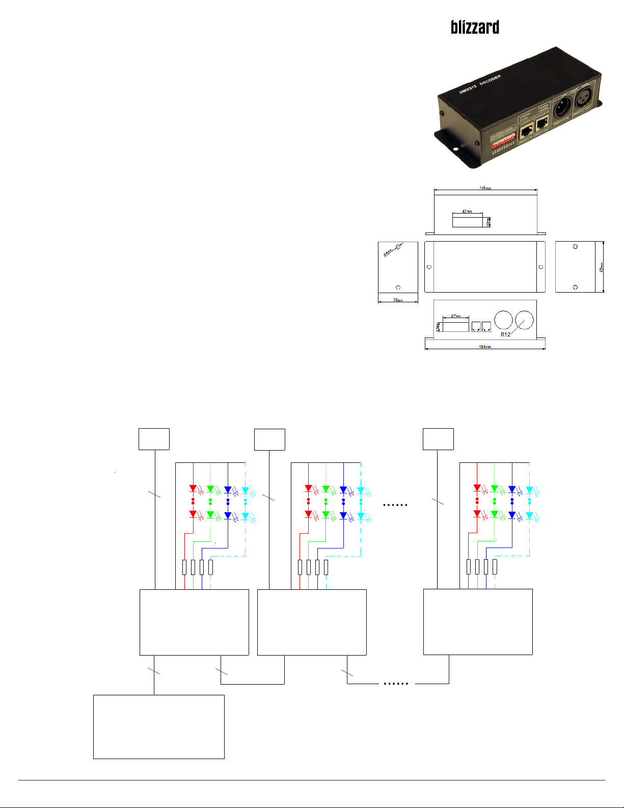
Typical Applications Setup Diagram
power
power
2 pin wire 2 pin wire
2 pin wire
External Dimension
Units in mm (+/-2mm)
power
com
power
KOMPLY™ DMX
signal in
3 pin wire
DMX signal out
DMX CONTROLLER
ch4ch2ch1
signal out
3 pin wire
com
ch3ch3
power
ch1ch2 ch4
KOMPLY™ DMX KOMPLY™ DMX
signal in
Copyright 2013 © All rights reserved
signal out
3 pin wire
Page 1/3
power
signal in
ch2ch1com
ch3
ch4
signal out
Page 2
Komply™ DMX
LOW VOLTAGE DMX DECODER (12/24VDC)
Interface specifications DMX input/output interface:
WW W.BLIZ ZA RD LIG HT ING .CO M
LIGHTING
3-pin-block as DMX signal interface.
DMX input and output interface
2: Optional RJ45 as signal
DMX Address code function setting
interface. Note ON is dip down.
interface to each unit. Only one
interface can be used.
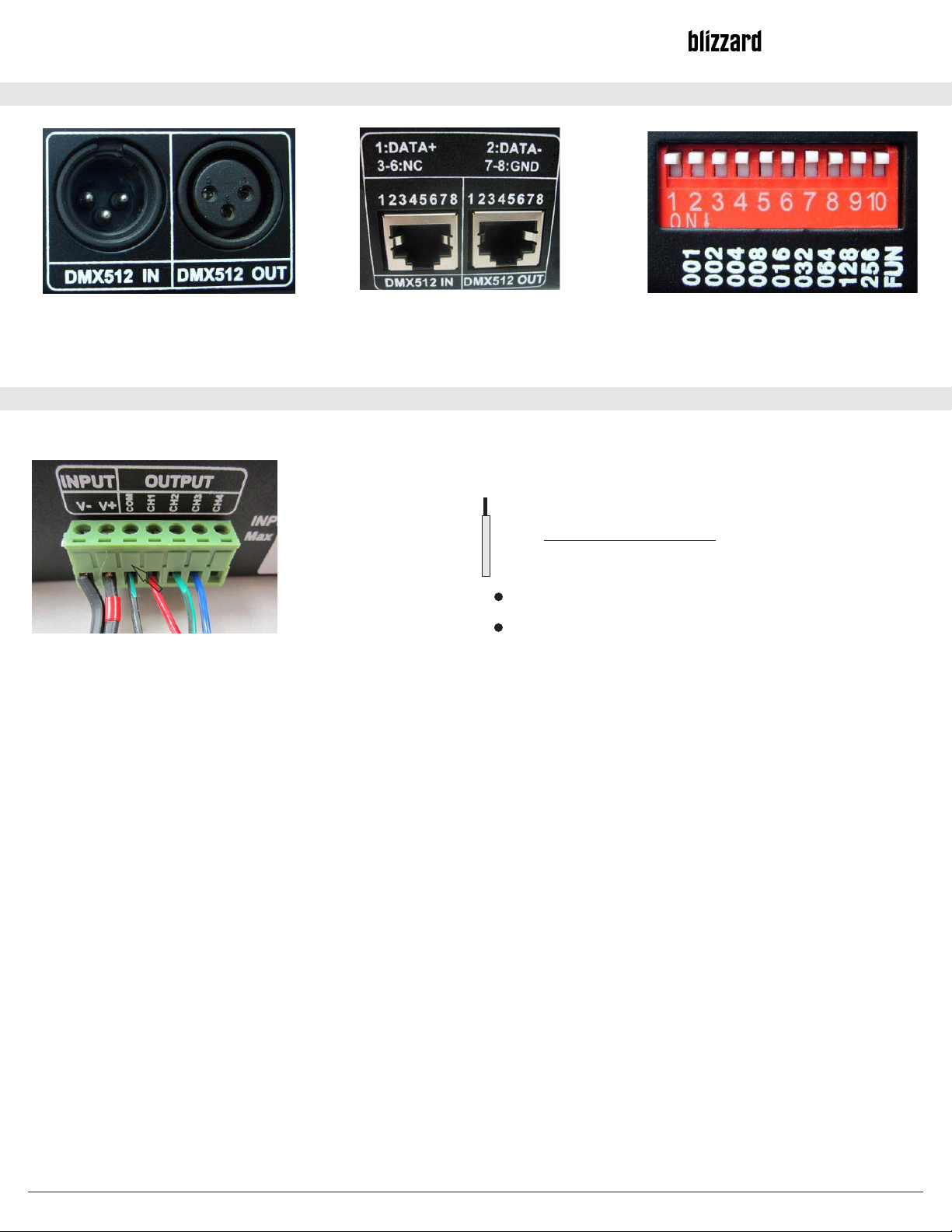
Low voltage input:
Under normal circumstances only three channels are used with low voltage RGB LED lighting but a fouth channel is available for
another color if required.
WARNING!
WIRE 6-8 MM (0.25-0.30")
EXPOSED WIRE SHOULD NOT BE MORE THAN 6- 8 MM LONG & SOLDER TIP
(tinned). DO NOT ALLOW WIRES TO CROSS AND INSURE ALL EXPOSED WIRE IS
-
-
-
+
+
-
-
-
If you’re attaching RGB Flex Strip to Komply™ DMX, correct
polarity is imperative; Black (may be white color wire) wire is
positive (+) and goes to “COM” terminal. The common format is
to insert the Red wire to CH1,Green wire to CH2 and Blue wire
to CH3 (RGB Format). If unit is set to DMX Channel 1, the unit
will automatically occupy Channels, 1,2,3 and 4 on the master
DMX console.
FULLY INSERTED INTO THE SCREW TERMINALS. HAND TIGHTEN SCREW
TERMINALS. USE ONLY 22 TO 16 GAUGE WIRE (NOT EXCEEDING 16 GAUGE) .
Input voltage must be identical to output voltage of the LED
Input: For low voltage power input (5VDC ~ 24VDC).
V- (negative) V+ (positive)
IMPORTANT NOTE:
COM: is for (+) Cathode
Ch1, CH2, CH3, CH4 are (-) Anode
If attaching a single color, the format is to attach the positive to
COM and negative to Ch1 (but can also be Channel 2, 3 or 4 if
desired).
TO AVOID ELECTRICAL SHOCK OR COMPONENT DAMAGE, DISCONNECT POWER BEFORE ATTEMPTING INSTALLATION OF THE POWER
Failure to install the power supplies and/or LED modules in accordance with the National Electric Code (NEC), all applicable Federal, State and local electric
codes as well as the specific Underwriters Laboratories (UL/CSA) safety standards for the installation, location and application may cause serious personal
injury, death, property damage and/or product malfunction. These instructions are guidelines for installation and power supplies. Installation requirements may
vary depending on the application. Licensed electricians should provide all installation services for connection of both primary and secondary
(input/output) of the power supplies.
Not for in wall installation.
Cable lighting systems be installed only in dry locations
Cable lighting systems not be installed in bathrooms; Keep away from water or wet areas.
Conductors of extra-low-voltage circuits be rigidly supported,
Conductors not be installed in contact with combustible materials and not run through walls, ceilings, floors or partitions, and; Uninsulated conductors not be
installed less than 2.2 m from the floor.
When using power supplies; the following basic safety features should be verified in addition to any other application specific concerns and local safety codes:
Short circuit protection
Overload protection (FUSE 5 AMP)
Overheat protection
Correct output voltage, including consideration for ripple and spikes.
WARNING: ONLY QUALIFIED PERSONNEL SHOULD PERFORM INSTALLATION.
SUPPLIES.
Copyright 2013 © All rights reserved
Page 2/3
Page 3

Komply™ DMX
LOW VOLTAGE DMX DECODER (12/24VDC)
LIGHTING
WW W.BLIZ ZA RD LIG HT ING .CO M
Direction for use:
DMX address code settings:
Each DMX controller occupies 4 sequential DMX addresses. Use the dip switches on the front to set the address in Binary code.
For example, if the DMX controller is set to address 1, then channels 1 through 4 are occupied. 511 addresses can be set using
the dip switches. Switches 1 through 9 are to set the DMX address and switches 10 is used to testing and function mode.
Switches from 1 to 9; 1 is the lowest, and 9 is the highest.
DMX original address code is equal to the total value of the coding switch value from 1 to 9 turned on; flip the dip switch
downwards (ON is at 1). The value of switch can be determined by adding the numbers value under the dip switch number (i.e.
001, 002 ect…)
DMX signal can only be received when coding switch FUN(10)=OFF(up).
Example 1:
Look at the following picture. If you want to set the DMX address to 37, set the first switch dip down as well as, the third and the
sixth code switch dip. The total value of coding switch value from 1 to 9 is 32 + 4 + 1, (001 + 004 + 032= 37) that is, the address
code of DMX512 is 37.
Example 2:
Look at the following picture, if you want to set 328 as the address code, you can only switch down the ninth, the seventh and the
fourth code switches; the total value of dip switch is 256+64+8 , (using switches 1-9 only) is 328.
1. Testing function: FUN
The tenth DIP switch is called “FUN” and has a built-in function button. FUN=OFF allows the use of the DMX decoder functions.
Using FUN you can test different functions if using three color LED RGB.
With the FUN switch DIP to ON: The default coding switch1-9 is off: Black.
Note; the following common format RGB format is used Red to CH1, Green to CH2 and Blue to CH3 (RGB Format).
Switch1=ON: red
Switch2=ON: green
Switch3=ON: blue
Switch4=ON: yellow
Switch5=ON: purple
Switch6=ON: cyan
Switch7=ON: white
Switch8=ON: seven-color jumpy changing (8 steps speed)
Copyright 2013 © All rights reserved
Page 3/3
 Loading...