

Page 1
TM
Blizzard Lighting, LLC
www.blizzardlighting.com
Waukesha, WI USA
Copyright (c) 2019
Page 2

TABLE OF CONTENTS
Weather System™ EXA 1
1. Getting Started 3
What’s In The Box? 3
Getting It Out Of The Box 3
Powering Up! 3
Getting A Hold Of Us 3
Safety Instructions (Don’t run with scissors!) 4
2. Meet The Weather System™ EXA 5
Main Features 5
DMX Quick Reference 5
The Weather System™ EXA Pin-up Picture 6
3. Setup 7
Connecting A Bunch Of Weather Systems 7
Data/DMX Cables 7
Setting the DMX Input Connector as the Active DMX Input 7
Cable Connectors 8
3-Pin??? 5-Pin??? Huh? 8
Take It To The Next Level: Setting up DMX Control 8
Fixture Linking (Master/Slave Mode) 9
Mounting/Rigging 9
4. Operating Adjustments 10
Navigating The Control Panel 10
Control Panel Menu Structure 11
DMX Mode 12
Set the Starting DMX Address 12
Setting the DMX Channel Mode 12
Slave Mode 12
Dimming Mode Settings 12
Static Colors and Strobe Effects 12
LED Display On/Off 12
Auto, Speed, and Sound Active Modes 13
Fixture Reset Functions 13
Footswitch Setup 13
Set the Footswitch Wireless Address 14
Multiple Fixtures With Footswitch Control 14
The Weather System™ EXA Footswitch Controller 14
Charging the Footswitch 14
DMX Value In-Depth Reference Guide 15
DMX In-Depth Reference 16
5. Appendix 20
A Quick DMX Lesson 20
Troubleshooting 20
Keeping Your Weather System™ EXA As Good As New 21
Returns (Gasp!) 21
Shipping Issues 21
Tech Specs 22
Dimensional Drawings 23
Weather System EXA Manual Rev. D © 2019 Blizzard Lighting, LLC
Page 2
Page 3

1. GETTING STARTED
What’s In The Box?
• 1 x Weather System™ EXA Fixture w/Case
• 1 x Tripod Lighting Stand
• 1 x Footswitch Controller
• 1 x USB to Micro-USB Cable with AC Adapter
• 1 x Ever-So-Handy Power Cord
• 4 x Accessory Knobs
• This Lovely User Manual
Getting It Out Of The Box
Congratulations on purchasing the Weather System™ EXA, the most far-out, featurepacked portable LED lighting systems on the market today! Now that you’ve got your
Weather System™ EXA (or hopefully, EXAs!), you should carefully unpack the box
and check the contents to ensure that all parts are present and in good condition. If
anything looks as if it has been damaged in transit, notify the shipper immediately
and keep the packing material for inspection. Again, please save the carton and all
packing materials. If a xture must be returned to the factory, it is important that
the xture be returned in the original factory box and packing.
Powering Up!
All xtures must be powered directly off a switched circuit and cannot be run off
a rheostat (variable resistor) or dimmer circuit, even if the rheostat or
dimmer channel is used solely for a 0% to 100% switch.
AC Voltage Switch - Not all xtures have a voltage select switch, so please verify that
the xture you receive is suitable for your local power supply. See the label on the
xture or refer to the xture’s specications chart for more information. A xture’s
listed current rating is its average current draw under normal conditions. Check the
xture or device carefully to make sure that if a voltage selection switch exists that it
is set to the correct line voltage you will use.
Warning! Verify that the voltage select switch on your unit matches the
line voltage applied. Damage to your xture may result if the line voltage
applied does not match the voltage indicated on the voltage selector switch.
All xtures must be connected to circuits with a suitable Ground (Earthing).
Getting A Hold Of Us
If something is wrong, please just visit our website at www.blizzardlighting.
com/support and open a support ticket. We’ll be happy to help, honest.
Disclaimer: The information and specications contained in this document are
subject to change without notice. Blizzard Lighting™ assumes no responsibility or
liability for any errors or omissions that may appear in this user manual. Blizzard
Lighting™ reserves the right to update the existing document or to create a new
document to correct any errors or omissions at any time. You can download the
latest version of this document from www.blizzardlighting.com.
Author: Date: Last Edited: Date:
J. Thomas 4/27/2016 J. Thomas 1/15/2019
Weather System EXA Manual Rev. D © 2019 Blizzard Lighting, LLC
Page 3
Page 4
SAFETY INSTRUCTIONS
• Please keep this User Guide for future use. If you sell the unit to someone
else, be sure that they also receive this User Guide.
• ALWAYS make sure that you are connecting to the proper voltage, and that
the line voltage you are connecting to is not higher than that stated on the
decal or rear panel of the xture.
• This product is intended for indoor use only.
• To prevent risk of re or shock, do not expose xture to rain or moisture.
• Make sure there are no ammable materials close to the unit while operating.
• The unit must be installed in a location with adequate ventilation, at least
20in (50cm) from adjacent surfaces. Be sure that no ventilation slots are
blocked.
• ALWAYS disconnect from the power source before servicing or replacing fuse
and be sure to replace with same fuse size and type.
• ALWAYS secure xture using a safety chain. NEVER carry the xture by its
cord. Use its carrying handles.
• DO NOT operate at ambient temperatures higher than 104°F (40°C).
• In the event of a serious operating problem, stop using the unit immediately.
NEVER try to repair the unit by yourself. Repairs carried out by unskilled people
can lead to damage or malfunction. Please contact the nearest authorized
technical assistance center. Always use the same type spare parts.
• NEVER connect the device to a dimmer pack.
• Make sure the power cord is never crimped or damaged.
• Never disconnect the power cord by pulling or tugging on the cord.
• Avoid direct eye exposure to the light source while it is on.
Caution! There are no user serviceable parts inside this unit. Do not open the
housing or attempt any repairs yourself. In the unlikely event your unit may
require service, please visit http://www.blizzardlighting.com/support.
Weather System EXA Manual Rev. D © 2019 Blizzard Lighting, LLC
Page 4
Page 5
2. MEET THE WEATHER SYSTEM™ EXA
MAIN FEATURES
• 8 xtures, each with 3* 15W 6-in-1 RGBAW+UV LEDs, 100,000 hours
• Independent xture swivel & tilt positioning
• Wireless rechargeable battery powered footswitch
• Built-in color macros and auto programs via DMX
• Color mixing ability in standalone mode
• Easy to use LED digital control panel
• User selectable 32-bit dimming curves
• Flicker-free constant-current 1500HZ LED driver
• Adjustable stand, dual hanging brackets, & carrying case
• 6CH/7CH/12CH/18CH/30CH/48CH or 54-channel DMX modes
• Heavy duty, black aluminum housing
• Natural convection cooled, totally silent operation
• 3-pin XLR input and output connections
• PowerCon™ compatible AC power In/Out connectors
DMX Quick Reference - 54/48/30/18-Channel Modes
54CH 48CH 30CH 18CH What it Does 54CH 48CH 30CH 18CH What it Does
1 -- 1 1 Dimmer 28 27 -- -- Blue 5
2 1 2 2 Red 1 29 28 -- -- Amber 5
3 2 3 3 Green 1 30 29 -- -- White 5
4 3 4 4 Blue 1 31 30 -- -- UV 5
5 4 5 5 Amber 1 32 31 -- -- Red 6
6 5 6 6 White 1 33 32 -- -- Green 6
7 6 7 7 UV 1 34 33 -- -- Blue 6
8 7 8 8 Red 2 35 34 -- -- Amber 6
9 8 9 9 Green 2 36 35 -- -- White 6
10 9 10 10 Blue 2 37 36 -- -- UV 6
11 10 11 11 Amber 2 38 37 -- -- Red 7
12 11 12 12 White 2 39 38 -- -- Green 7
13 12 13 13 UV 2 40 39 -- -- Blue 7
14 13 14 -- Red 3 41 40 -- -- Amber 7
15 14 15 -- Green 3 42 41 -- -- White 7
16 15 16 -- Blue 3 43 42 -- -- UV 7
17 16 17 -- Amber 3 44 43 -- -- Red 8
18 17 18 -- White 3 45 44 -- -- Green 8
19 18 19 -- UV 3 46 45 -- -- Blue 8
20 19 20 -- Red 4 47 46 -- -- Amber 8
21 20 21 -- Green 4 48 47 -- -- White 8
22 21 22 -- Blue 4 49 48 -- -- UV 8
23 22 23 -- Amber 4 50 -- 26 14 Strobe/Shutter
24 23 24 -- White 4 51 -- 27 15 Auto
25 24 25 -- UV 4 52 -- 28 16 Auto Color
26 25 -- -- Red 5 53 -- 29 17 Auto Speed
27 26 -- -- Green 5 54 -- 30 18 32-bit Dimming
DMX Quick Reference - 12/7/6-Channel Modes
CH 12-Channel Mode 7-Channel Mode 6-Channel Mode
1 Dimmer Dimmer Red Intensity
2 Red Intensity Red Intensity Green Intensity
3 Green Intensity Green Intensity Blue Intensity
4 Blue Intensity Blue Intensity Amber Intensity
5 Amber Intensity Amber Intensity White Intensity
6 White Intensity White Intensity UV Intensity
7 UV Intensity UV Intensity -8 Strobe/Shutter -- -9 Auto -- -10 Auto Color -- -11 Auto Speed -- -12 32-bit Dimming -- --
Weather System EXA Manual Rev. D © 2019 Blizzard Lighting, LLC
Page 5
Page 6
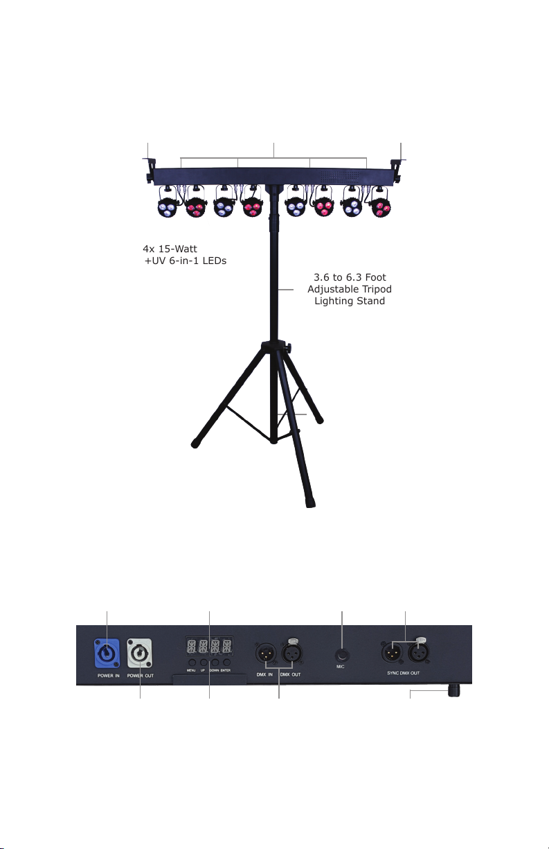
Figure 1: The Weather System™ EXA Pin-Up Picture
Mounting
Bracket
24x 15-Watt
RGBAW+UV 6-in-1 LEDs
Threaded Accessory Knob
Mounting Holes
Mounting
Bracket
3.6 to 6.3 Foot
Adjustable Tripod
Lighting Stand
Figure 2: The Rear Connections
Power Input
Power Output
Weather System EXA Manual Rev. D © 2019 Blizzard Lighting, LLC
Control Panel
Menu Buttons
DMX In/Out
Page 6
DMX Sync OutMic
Mic Sensitivity Knob
Page 7
3. SETUP
Fuse Replacement
CAUTION! The Weather System™ EXA utilizes a high-output switch-
mode power supply with an internal fuse. Under normal operating
conditions, the fuse should not require replacement. The fuse is eld
replaceable, however it is an advanced procedure suited to qualied
individuals. Should your Weather System™ fuse require replacement,
please contact Blizzard Lighting for instructions, or to return for service.
Connecting A Bunch of Weather System™ Fixtures
You will need a serial data link to run light shows using a DMX-512
controller or to run shows on two or more xtures set to sync in master/
slave operating mode. The combined number of channels required by all
the xtures on a serial data link determines the number of xtures the
data link can support.
Fixtures on a serial data link must be daisy chained in one single line.
Also, connecting more than 32 xtures on one serial data link without the
use of a DMX optically-isolated splitter may result in deterioration of the
digital DMX signal. The maximum recommended cable-run distance is
500 meters (1640 ft). The maximum recommended number of xtures
on a serial data link is 32 xtures.
Data/DMX Cabling
To link xtures together you’ll need data cables. You should use data-
grade cables that can carry a high quality signal and are less prone to
electromagnetic interference.
For instance, Belden© 9841 meets the specications for EIA RS-485
applications. Standard microphone cables will “probably” be OK, but note
that they cannot transmit DMX data as reliably over long distances. In
any event, the cable should have the following characteristics:
2-conductor twisted pair plus a shield
Maximum capacitance between conductors – 30 pF/ft.
Maximum capacitance between conductor & shield – 55 pF/ft.
Maximum resistance of 20 ohms / 1000 ft.
Nominal impedance 100 – 140 ohms
Weather System EXA Manual Rev. D © 2019 Blizzard Lighting, LLC
Page 7
Page 8
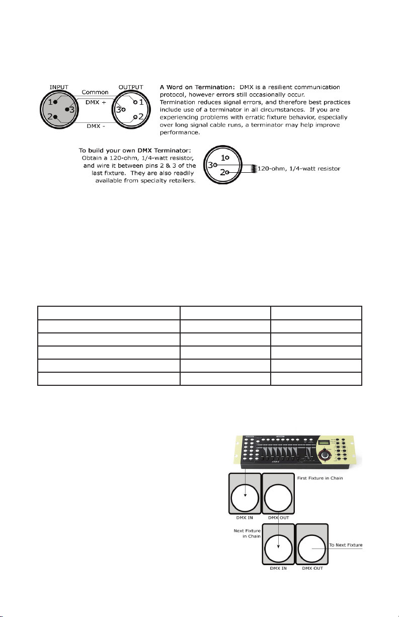
Cable Connectors
Cables must have a male XLR connector on one end and a female XLR connector on the other end. (Duh!)
CAUTION: Do not allow contact between the common and the
xture’s chassis ground. Grounding the common can cause a ground
loop, and your xture may perform erratically. Test cables with an
ohm meter to verify correct polarity and to make sure the pins are not
grounded or shorted to the shield or each other.
3-Pin??? 5-Pin??? Huh?!?
If you use a controller with a 5-pin DMX output connector, you will need to use a 5 pin to 3 pin adapter.
They are widely available over the internet and from specialty retailers If you’d like to build your own, the
chart below details a proper cable conversion:
Conductor 3-Pin Female (Output) 5-Pin Male (Input)
Ground/Shield Pin 1 Pin 1
Data 1- (Primary Data Link) Pin 2 Pin 2
Data 1+ (Primary Data Link) Pin 3 Pin 3
Data 2- (Optional Secondary Data Link) Pin 4 Pin 4
Data 2+ (Optional Secondary Data Link) Pin 5 Pin 5
Take It To The Next Level: Setting Up DMX Control
Step 1: Connect the male connector of the DMX cable to the female connector (output) on
the controller.
Step 2: Connect the female connector of the
DMX cable to the rst xture’s male connector
(input). Note: It doesn’t matter which
xture address is the rst one connected. We
recommend connecting the xtures in terms
of their proximity to the controller, rather than
connecting the lowest xture number rst, and
so on.
Step 3: Connect other xtures in the chain
from output to input as above. Place a DMX
terminator on the output of the nal xture to
ensure best communication.
Weather System EXA Manual Rev. D © 2019 Blizzard Lighting, LLC
Page 8
Page 9

Fixture Linking (Master/Slave Mode)
1. Connect the (male) 3-pin connector side of the
DMX cable to the output (female) 3-pin connector of
the rst xture.
2. Connect the end of the cable coming from
the rst xture which will have a (female) 3-pin
connector to the input connector of the next xture
consisting of a (male) 3-pin connector. Then,
proceed to connect from the output as stated above
to the input of the following xture and so on.
A quick note: Often,
the setup for MasterSlave and Standalone
operation requires that
the rst xture in the
chain be initialized for
this purpose via either
settings in the control
panel or DIP-switches.
Secondarily, the xtures
that follow may also
require a slave setting.
Check the “Operating Adjustments” section in this manual for com-
plete instructions for this type of setup and conguration.
Mounting & Rigging
This xture may be mounted in any SAFE position provided there is
enough room for ventilation.
It is important never to obstruct the fan or vents pathway. Mount the
xture using suitable “C” or “O” type clamps. Clamps should be rated
to hold at least 10x the xture’s weight to ensure structural stability.
Do not mount to surfaces with unknown strength, and ensure properly
“rated” rigging is used when mounting xtures overhead.
Adjust the angle of the xture by loosening both knobs and tilting the
xture. After nding the desired position, retighten both knobs.
• When selecting installation location, take into consideration lamp
replacement access (if applicable) and routine maintenance.
• When mounting the head, safety cables MUST ALWAYS be used.
• Never mount in places where the xture will be exposed to rain,
high humidity, extreme temperature changes or restricted ventilation.
Weather System EXA Manual Rev. D © 2019 Blizzard Lighting, LLC
Page 9
Page 10

4. OPERATING ADJUSTMENTS
The Control Panel
All the goodies and different modes possible with the Weather System™ EXA
are accessed by using the control panel on the rear of the xture. There are 4
control buttons below the LED display which allow you to navigate through the
various control panel menus.
<MENU>
Is used to navigate to the previous higher-level menu item.
<UP>
Scrolls through menu items and numbers in ascending order.
<DOWN>
Scrolls through menu items and numbers in descending order.
<ENTER>
Is used to select and conrm/store the current selection.
The control panel LED display shows the menu items you select from the menu
map on page #11. When a menu function is selected, the display will show im-
mediately the rst available option for the selected menu function. To select a
menu item, press <ENTER>.
Use the <UP> and <DOWN> buttons to navigate the menu options. Press the
<ENTER> button to select the menu function currently displayed, or to enable
a menu option. To return to the previous option or menu without changing the
value, press the <MENU> button.
Weather System EXA Manual Rev. D © 2019 Blizzard Lighting, LLC
Page 10
Page 11
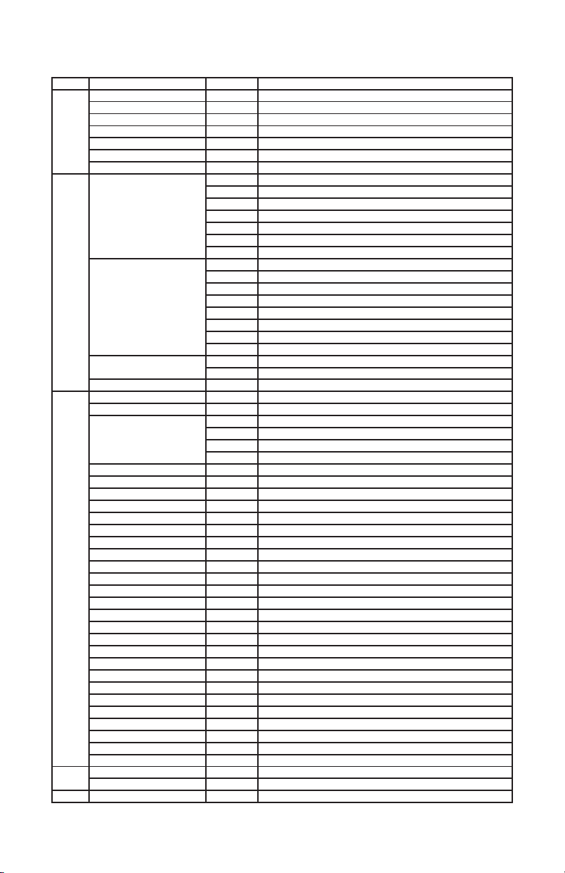
Control Panel Menu Structure
ADDR 001-512 <ENTER> To choose the DMX address
STAT R 0-255 Red intensity (0% <--> 100%)
G 0-255 Green intensity (0% <--> 100%)
B 0-255 Blue intensity (0% <--> 100%)
A 0-255 Amber intensity (0% <--> 100%)
W 0-255 White intensity (0% <--> 100%)
UV 0-255 UV intensity (0% <--> 100%)
SHUT 0-255 Flash / strobe speed (slow <--> fast)
SET CHMD (channel mode) 54CH 54-channel mode
DIM (dimming mode) LIN Linear
DISY (display set)
WADD (wireless address)
AUTO INTE (intensity) 0-255 Set the intensity level (dim to bright)
ACCT No/1-255 Automatic color change after set number of auto loops
ATMD (auto mode) STEP Auto Step Mode (individual steps)
AT01 0-255 Auto program 1, speed (0-255)
AT02 0-255 Auto program 2, speed (0-255)
AT03 0-255 Auto program 3, speed (0-255)
AT04 0-255 Auto program 4, speed (0-255)
AT05 0-255 Auto program 5, speed (0-255)
AT06 0-255 Auto program 6, speed (0-255)
AT07 0-255 Auto program 7, speed (0-255)
AT08 0-255 Auto program 8, speed (0-255)
AT09 0-255 Auto program 9, speed (0-255)
AT10 0-255 Auto program 10, speed (0-255)
AT11 0-255 Auto program 11, speed (0-255)
AT12 0-255 Auto program 12, speed (0-255)
AT13 0-255 Auto program 13, speed (0-255)
AT14 0-255 Auto program 14, speed (0-255)
AT15 0-255 Auto program 15, speed (0-255)
AT16 0-255 Auto program 16, speed (0-255)
AT17 0-255 Auto program 17, speed (0-255)
AT18 0-255 Auto program 18, speed (0-255)
AT19 0-255 Auto program 19, speed (0-255)
AT20 0-255 Auto program 20, speed (0-255)
AT21 0-255 Auto program 21, speed (0-255)
AT22 0-255 Auto program 22, speed (0-255)
SOU1 <ENTER>
SOU2 <ENTER>
SOU3 <ENTER>
INFO
SOFT Vx.x Software version information
POW
LOAD
YES/NO
48CH 48-channel DMX mode
30CH 30-channel DMX mode
18CH 18-channel DMX mode
12CH 12-channel DMX mode
7CH 7-channel DMX mode
6CH 6-channel DMX mode
SQR Square law
ISQR Inverse square law
SCUR S-curve
LIN. Linear (smooth)
SQR. Square law (smooth)
ISQR. Inverse square law (smooth)
SCUR. S-curve (smooth)
ON LED menu display is continually on
2M LED menu display off after 2 minutes
0-F Set to match the footswitch frequency address
0SHT Auto “One Shot” Mode (run program once)
LOOP Auto Loop (loop program)
BPM Beats Per Minute (tap sync)
Sound Active Mode 1 (color changing)
Sound Active Mode 2 (white strobe)
Sound Active Mode 3 (color chase)
<ENTER>
<ENTER>
Display current power reduction percentage
Reset all factory defaults (except for ADDR and WADD)
Weather System EXA Manual Rev. D © 2019 Blizzard Lighting, LLC
Page 11
Page 12

DMX Mode
Allows the unit to be controlled by any universal DMX controller.
Setting the Starting DMX Address:
1.) To select a starting DMX address for your xture, navigate the main menu to reach ADDR,
then press <ENTER>. Now use the <UP/DOWN> buttons to select any stating DMX address
value ranging between 001-512, then press <ENTER> to conrm your choice.
Setting the DMX Channel Mode:
1.) To select a DMX channel mode, navigate the main menu to reach SET, then press
<ENTER>. Then use the <UP/DOWN> buttons to highlight CHMD, and press <ENTER>.
From here you can select your desired DMX channel mode, and press <ENTER> to conrm.
Slave Mode:
1.) Daisy chain the xtures via DMX In/Out, with the controller at the beginning.
2.) Set starting DMX channels and DMX channel modes all to match the master xture.
3.) The rst xture in the DMX chain is the master xture, and the following are slave xtures.
For wireless footswitch master/slave setup, see Footswitch Setup on page 13.
Dimming Mode Settings:
Allows users to set the xture to use 1 of 4 (x2) dimming curve settings for smoother (and slower)
dimming capabilities. In the control panel menu, there are two settings for each curve that are
distinguishable from one another by the trailing dot.
Linear Curve Square Law Inverse Square Law S-Curve
(LIN, LIN.) (SQR, SQR.) (ISQR, ISQR.) (SCUR, SCUR.)
Output
DMX% DMX% DMX% DMX%
*The curve settings with the trailing dot adds a bit more delay to the curve for a smoother effect.
1.) Use the <MENU> and <UP/DOWN> buttons to navigate to SET and press <ENTER>,
then <UP/DOWN> buttons again to scroll to DIM, and press the <ENTER> button.
2.) Now use the <UP/DOWN> buttons to highlight either LIN (Linear), SQR (Square), ISQR
(Inverse Square), SCUR (S-Curve), LIN. (Smooth Linear), SQR. (Smooth Square), ISQR.
(Smooth Inverse Square), or SCUR. (Smooth S-Curve), then hit <ENTER>.
Output
Output
Output
Static Colors and Strobe Effects:
Allows the user to manually adjust RGBAW+UV color balance and strobe.
1.) Use the <MENU> and <UP/DOWN> buttons to navigate to STAT and press <ENTER>,
then <UP/DOWN> buttons to select R/G/B/A/W/UV or SHUT (strobe) and press the
<ENTER> button.
2.) Now use the <UP/DOWN> buttons to highlight any value ranging from 0-255 to adjust the
intensity level, and press the <ENTER> button to conrm.
LED Display On/Off:
1.) Use the <MENU> and <UP/DOWN> buttons to navigate to SET and press <ENTER>,
then navigate to DISY, and press the <ENTER> button.
2.) In DISY, you can set the LED menu display to be continually on by selecting ON, or shut off
after 2 minute of inactivity by selecting 2MIN. Press <ENTER> to conrm.
Weather System EXA Manual Rev. D © 2019 Blizzard Lighting, LLC
Page 12
Page 13

Auto Mode and Auto Speed Settings:
Set single or Master/Slaved units to run in auto mode at user selectable speeds.
Auto Mode:
1.) Use the <MENU> and <UP/DOWN> buttons to navigate to navigate to AUTO, and press
the <ENTER> button.
2.) Now use the <UP/DOWN> buttons to highlight any program ranging from AT01-AT22,
and press <ENTER>.
3.) From here, you can now adjust the auto speed. Use the <UP/DOWN> buttons to select a
value ranging from 0-255 (fast <--> slow), and press <ENTER> to conrm.
4.) In this same menu level as AT01-AT22, you can also edit INTE (overall LED intensity
output level: 0-255), ACCT (color change after set number of loops: 1-255), and ATMD which
allows for 4 different auto mode selection types: STEP (individual steps, triggered by TAP SYC
on footswitch), 1SHT (run program once, triggered by TAP SYC on footswitch), LOOP (loops
a running auto program), and BPM (auto-run speed will match the rate that the TAP SYC
footswitch is tapped on, either fast or slow).
Sound Active Mode:
1.) Use the <MENU> and <UP/DOWN> buttons to navigate to AUTO and press <ENTER>,
then with the <UP/DOWN> buttons navigate to SOU1 (color change), or SOU2 (white strobe
only), and press the <ENTER> button.
Fixture Reset Functions:
Allows users to reset the xture to factory default settings with the exception ADDR or WADD.
1.) Use the <MENU> and <UP/DOWN> buttons to navigate to LOAD and press <ENTER>,
then use the <UP/DOWN> buttons to highlight YES or NO, then press <ENTER>.
2.) The reset function will reset all default values with the exception of those in ADDR
(address), and WADD (wireless address).
Footswitch Setup:
Set the Footswitch Wireless Address:
1.) Navigate the main menu of the xture(s) to be controlled by the footswitch to reach SET and
then press <ENTER>.
2.) Use the <UP/DOWN> buttons to scroll to WADD, and press <ENTER>.
3.) Now use the <UP/DOWN> buttons to select any frequency from 0-F, and press <ENTER>.
4.) On the footswitch, use the channel selection button to choose the same frequency that is set
on the xture(s) from 0-F.
Master/Slave Multiple Wireless Fixtures
1.) Set the WADD (wireless address) of master xture as 0.
2.) Set the address of the foot pedal to 0.
3.) Set the WADD of the slave xture to anything other than 0.
4.) Set the DMX address on both xtures to 001.
5.) Set the channel mode (CHMD) on both xtures to 48ch.
6.) Connect a 3-Pin DMX cable from the Sync DMX output of the master xture and plug it into
the DMX Input of the slave.
Note #1: When the footswitch channel selection button is not in use for 10s, the LED display will
change and revert to showing the remaining battery power level from 0-9.
Note #2: The rst xture in the DMX chain is the only xture needing to use the Sync Dmx
Out port. Both of the Sync Dmx Out rear connections (male and female) are outputs.
Weather System EXA Manual Rev. D © 2019 Blizzard Lighting, LLC
Page 13
Page 14
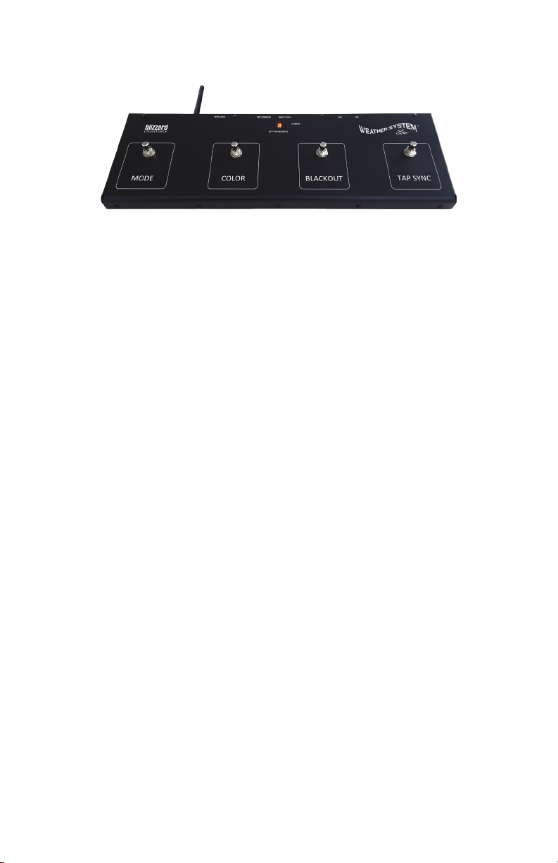
The Weather System™ EXA Footswitch Controller
*Important: Be sure to swivel the antennas of the footswitch and xture(s) to their outward
extended positions to ensure the best possible signal reception. And note that when the channel
selection button of the footswitch is not in use for 10s, the LED display will show the remaining
battery power level from 0-9.
Pedal 1: Mode
The mode switch gives you the option to select built-in auto programs and sound
active modes. After the rst press to activate it, continue to use the mode switch
to cycle through all of its built-in programs ranging from AT01-AT22, then its
sound active modes SOU1-SOU3. The running speed for each auto program can
be adjusted using the xture’s LED control panel menu, or by using the Tap Sync
switch when the auto mode is set to loop.
Pedal 2: Color
When you step on the color switch, it triggers an instant change in color to any
running auto program. Tip: for full xture solid color control with no chase pat
terns, set the xture to Auto Mode: Loop, then Program 1 (AT01), and use the
color switch to change color.
-
Pedal 3: Blackout
When you step on the blackout footswitch, it will blackout the currently running
program. Step on this pedal again, and the Weather System™ EXA will continue
running the program where it left off.
Pedal 4: Tap Sync
When ATMD (auto mode) in the control panel menu is set to LOOP, the Tap Sync
footswitch adjusts the running speed (0-255), then step on the Mode switch to
save. When ATMD is set to STEP (individual steps), ONE-SHOT (run program
once), or BPM (tap controlled speed) the Tap Sync switch will trigger an action.
Charging the Battery
The battery in the wireless footswitch controller can last up to 18 hours on a single
charge. You can use the included
USB to Micro-USB cable to charge it via USB
port, or plug it into a standard wall socket using the included USB-AC Adapter.
A full battery charge can take up to 5 hours, and the charge LED indicator will
illuminate green when complete.
Weather System EXA Manual Rev. D © 2019 Blizzard Lighting, LLC
Page 14
Page 15

DMX Value In-Depth Reference Guide
Function Value What It Does
Dimmer 000 <--> 255 (0% <--> 100%)
Red Intensity 000 <--> 255 (0% <--> 100%)
Green Intensity 000 <--> 255 (0% <--> 100%)
Blue Intensity 000 <--> 255 (0% <--> 100%)
Amber Intensity 000 <--> 255 (0% <--> 100%)
White Intensity 000 <--> 255 (0% <--> 100%)
UV Intensity 000 <--> 255 (0% <--> 100%)
Strobe 000 <--> 020
Effect 000 <--> 005
Auto Color 000 <--> 010
Auto Speed 000 <--> 255 Auto Speed (fast <--> slow)
Dimming Mode 000 <--> 010
021 <--> 060
061 <--> 100
101 <--> 140
141 <--> 180
181 <--> 220
221 <--> 255
006 <--> 010
011 <--> 015
016 <--> 020
021 <--> 025
026 <--> 030
031 <--> 035
036 <--> 040
041 <--> 045
046 <--> 050
051 <--> 055
056 <--> 060
061 <--> 065
066 <--> 070
071 <--> 075
076 <--> 080
081 <--> 085
086 <--> 090
091 <--> 095
096 <--> 100
101 <--> 105
106 <--> 110
111 <--> 115
116 <--> 235
236 <--> 240
241 <--> 245
246 <--> 250
251 <--> 255
011 <--> 020
021 <--> 030
031 <--> 040
041 <--> 050
051 <--> 060
061 <--> 070
071 <--> 080
081 <--> 090
091 <--> 100
101 <--> 110
111 <--> 120
121 <--> 130
131 <--> 140
141 <--> 255
011 <--> 020
021 <--> 030
031 <--> 040
041 <--> 050
051 <--> 060
061 <--> 070
071 <--> 080
081 <--> 090
091 <--> 255
No strobe
Normal strobe (slow <--> fast)
Electronic sine wave (slow <--> fast)
Random strobe (slow <--> fast)
Opening pulse (slow <--> fast)
Closing pulse (slow <--> fast)
Electronic square wave (slow <--> fast)
No Function
AUTO1: Footswitch triggered; LOOP: open, 0SHT/STEP: ash
AUTO2: One xture step running
AUTO3: Two xture step running
AUTO4: Two xture two space step running
AUTO5: Four xture step running
AUTO6: Fixture 1 to 8 open then dark
AUTO7: Fixture 1 to 8 open then 8 to 1 open
AUTO8: Two xture random
AUTO9: One xture random
AUTO10: Center to side open then dark
AUTO11: Side to center open then dark
AUTO12: Fixture 1 to 8 open
AUTO13: Two xture left to right open
AUTO14: Two xture left to right open then reverse
AUTO15: Fixture 1 to 8 step running then reverse
AUTO16: Fixture 1 to 8 open then dark with background color
AUTO17: Two xture left to right with background color
AUTO18: Fixture 1 to 8 open with background color
AUTO19: Four piece step running with background color
AUTO20: Center to side with background color
AUTO21: Each xture changes color individually
AUTO22: Auto programs AT01-AT20
No Function
Sound active mode 1 (color change)
Sound active mode 2 (white strobe)
Sound active mode 3 (color chase)
No Function
No Function
Red
Green
Blue
Amber
White
UV
Red + Green
Red + Blue
Green + Blue
Red + Amber
RGBAW+UV
Orange
Magenta
No Function
32-Bit Dimmer
As set in the control menu display
Linear curve not smooth
Square law curve not smooth
Inverse square law curve not smooth
S-curve not smooth
Linear curve and smooth
Square law curve and smooth
Inverse square law curve and smooth
S-curve and smooth
Weather System EXA Manual Rev. D © 2019 Blizzard Lighting, LLC
Page 15
Page 16

DMX In-Depth Reference: 54-Channel Mode
Channel Name Channel Name
1 Dimmer (0%<--> 100%) 28 Blue 5 (0%<--> 100%)
2 Red 1 (0%<--> 100%) 29 Amber 5 (0%<--> 100%)
3 Green 1 (0%<--> 100%) 30 White 5 (0%<--> 100%)
4 Blue 1 (0%<--> 100%) 31 UV 5 (0%<--> 100%)
5 Amber 1 (0%<--> 100%) 32 Red 6 (0%<--> 100%)
6 White 1 (0%<--> 100%) 33 Green 6 (0%<--> 100%)
7 UV 1 (0%<--> 100%) 34 Blue 6 (0%<--> 100%)
8 Red 2 (0%<--> 100%) 35 Amber 6 (0%<--> 100%)
9 Green 2 (0%<--> 100%) 36 White 6 (0%<--> 100%)
10 Blue 2 (0%<--> 100%) 37 UV 6 (0%<--> 100%)
11 Amber 2 (0%<--> 100%) 38 Red 7 (0%<--> 100%)
12 White 2 (0%<--> 100%) 39 Green 7 (0%<--> 100%)
13 UV 2 (0%<--> 100%) 40 Blue 7 (0%<--> 100%)
14 Red 3 (0%<--> 100%) 41 Amber 7 (0%<--> 100%)
15 Green 3 (0%<--> 100%) 42 White 7 (0%<--> 100%)
16 Blue 3 (0%<--> 100%) 43 UV 7 (0%<--> 100%)
17 Amber 3 (0%<--> 100%) 44 Red 8 (0%<--> 100%)
18 White 3 (0%<--> 100%) 45 Green 8 (0%<--> 100%)
19 UV 3 (0%<--> 100%) 46 Blue 8 (0%<--> 100%)
20 Red 4 (0%<--> 100%) 47 Amber 8 (0%<--> 100%)
21 Green 4 (0%<--> 100%) 48 White 8 (0%<--> 100%)
22 Blue 4 (0%<--> 100%) 49 UV 8 (0%<--> 100%)
23 Amber 4 (0%<--> 100%) 50 Strobe
24 White 4 (0%<--> 100%) 51 Effect
25 UV 4 (0%<--> 100%) 52 Auto Color (fast <--> slow)
26 Red 5 (0%<--> 100%) 53 Auto Speed (fast <--> slow)
27 Green 5 (0%<--> 100%) 54 32-Bit Dimming Modes
Weather System EXA Manual Rev. D © 2019 Blizzard Lighting, LLC
Page 16
Page 17
DMX In-Depth Reference: 48-Channel Mode
Channel Name Channel Name
1 Red 1 (0%<--> 100%) 25 Red 5 (0%<--> 100%)
2 Green 1 (0%<--> 100%) 26 Green 5 (0%<--> 100%)
3 Blue 1 (0%<--> 100%) 27 Blue 5 (0%<--> 100%)
4 Amber 1 (0%<--> 100%) 28 Amber 5 (0%<--> 100%)
5 White 1 (0%<--> 100%) 29 White 5 (0%<--> 100%)
6 UV 1 (0%<--> 100%) 30 UV 5 (0%<--> 100%)
7 Red 2 (0%<--> 100%) 31 Red 6 (0%<--> 100%)
8 Green 2 (0%<--> 100%) 32 Green 6 (0%<--> 100%)
9 Blue 2 (0%<--> 100%) 33 Blue 6 (0%<--> 100%)
10 Amber 2 (0%<--> 100%) 34 Amber 6 (0%<--> 100%)
11 White 2 (0%<--> 100%) 35 White 6 (0%<--> 100%)
12 UV 2 (0%<--> 100%) 36 UV 6 (0%<--> 100%)
13 Red 3 (0%<--> 100%) 37 Red 7 (0%<--> 100%)
14 Green 3 (0%<--> 100%) 38 Green 7 (0%<--> 100%)
15 Blue 3 (0%<--> 100%) 39 Blue 7 (0%<--> 100%)
16 Amber 3 (0%<--> 100%) 40 Amber 7 (0%<--> 100%)
17 White 3 (0%<--> 100%) 41 White 7 (0%<--> 100%)
18 UV 3 (0%<--> 100%) 42 UV 7 (0%<--> 100%)
19 Red 4 (0%<--> 100%) 43 Red 8 (0%<--> 100%)
20 Green 4 (0%<--> 100%) 44 Green 8 (0%<--> 100%)
21 Blue 4 (0%<--> 100%) 45 Blue 8 (0%<--> 100%)
22 Amber 4 (0%<--> 100%) 46 Amber 8 (0%<--> 100%)
23 White 4 (0%<--> 100%) 47 White 8 (0%<--> 100%)
24 UV 4 (0%<--> 100%) 48 UV 8 (0%<--> 100%)
DMX In-Depth Reference: 30-Channel Mode
Channel Name Channel Name
1 Dimmer (0%<--> 100%) 16 Blue 3 (0%<--> 100%)
2 Red 1 (0%<--> 100%) 17 Amber 3 (0%<--> 100%)
3 Green 1 (0%<--> 100%) 18 White 3 (0%<--> 100%)
4 Blue 1 (0%<--> 100%) 19 UV 3 (0%<--> 100%)
5 Amber 1 (0%<--> 100%) 20 Red 4 (0%<--> 100%)
6 White 1 (0%<--> 100%) 21 Green 4 (0%<--> 100%)
7 UV 1 (0%<--> 100%) 22 Blue 4 (0%<--> 100%)
8 Red 2 (0%<--> 100%) 23 Amber 4 (0%<--> 100%)
9 Green 2 (0%<--> 100%) 24 White 4 (0%<--> 100%)
10 Blue 2 (0%<--> 100%) 25 UV 4 (0%<--> 100%)
11 Amber 2 (0%<--> 100%) 26 Strobe
12 White 2 (0%<--> 100%) 27 Effect
13 UV 2 (0%<--> 100%) 28 Auto Color (fast <--> slow)
14 Red 3 (0%<--> 100%) 29 Auto Speed (fast <--> slow)
15 Green 3 (0%<--> 100%) 30 32-Bit Dimming Modes
Weather System EXA Manual Rev. D © 2019 Blizzard Lighting, LLC
Page 17
Page 18

DMX In-Depth Reference: 18/12-Channel Modes
18-Channel Name 12-Channel Name
1 Dimmer (0%<--> 100%) 1 Dimmer (0%<--> 100%)
2 Red 1 (0%<--> 100%) 2 Red (0%<--> 100%)
3 Green 1 (0%<--> 100%) 3 Green (0%<--> 100%)
4 Blue 1 (0%<--> 100%) 4 Blue (0%<--> 100%)
5 Amber 1 (0%<--> 100%) 5 Amber (0%<--> 100%)
6 White 1 (0%<--> 100%) 6 White (0%<--> 100%)
7 UV 1 (0%<--> 100%) 7 UV (0%<--> 100%)
8 Red 2 (0%<--> 100%) 8 Strobe
9 Green 2 (0%<--> 100%) 9 Effect
10 Blue 2 (0%<--> 100%) 10 Auto Speed (fast <--> slow)
11 Amber 2 (0%<--> 100%) 11 Virtual Color Wheel
12 White 2 (0%<--> 100%) 12 32-Bit Dimming Modes
13 UV 2 (0%<--> 100%) -- --
14 Strobe -- --
15 Effect -- --
16 Auto Color (fast <--> slow) -- --
17 Auto Speed (fast <--> slow) -- --
18 32-Bit Dimming Modes -- --
DMX In-Depth Reference: 7/6-Channel Modes
7-Channel Name 6-Channel Name
1 Dimmer (0%<--> 100%) 1 Red (0%<--> 100%)
2 Red (0%<--> 100%) 2 Green (0%<--> 100%)
3 Green (0%<--> 100%) 3 Blue (0%<--> 100%)
4 Blue (0%<--> 100%) 4 Amber (0%<--> 100%)
5 Amber (0%<--> 100%) 5 White (0%<--> 100%)
6 White (0%<--> 100%) 6 UV (0%<--> 100%)
7 UV (0%<--> 100%) --- ---
Weather System EXA Manual Rev. D © 2019 Blizzard Lighting, LLC
Page 18
Page 19

5. APPENDIX
A Quick Lesson On DMX
DMX (aka DMX-512) was created in 1986 by the United States Institute for Theatre
Technology (USITT) as a standardized method for connecting lighting consoles to lighting
dimmer modules. It was revised in 1990 and again in 2000 to allow more exibility. The
Entertainment Services and Technology Association (ESTA) has since assumed control over
the DMX512 standard. It has also been approved and recognized for ANSI standard clas-
sication.
DMX covers (and is an abbreviation for) Digital MultipleXed signals. It is the most common
communications standard used by lighting and related stage equipment.
DMX provides up to 512 control “channels” per data link. Each of these channels was originally intended to control lamp dimmer levels. You can think of it as 512 faders on a lighting
console, connected to 512 light bulbs. Each slider’s position is sent over the data link as an
8-bit number having a value between 0 and 255. The value 0 corresponds to the light bulb
being completely off while 255 corresponds to the light bulb being fully on.
DMX data is transmitted at 250,000 bits per second using the RS-485 transmission standard over two wires. As with microphone cables, a grounded cable shield is used to prevent
interference with other signals.
There are ve pins on a DMX connector: a wire for ground (cable shield), two wires for
“Primary” communication which goes from a DMX source to a DMX receiver, and two wires
for a “Secondary” communication which goes from a DMX receiver back to a DMX source.
Generally, the “Secondary” channel is not used so data ows only from sources to receivers. Hence, most of us are most familiar with DMX-512 as being employer over typical
3-pin “mic cables,” although this does not conform to the dened standard.
DMX is connected using a daisy-chain conguration where the source connects to the input
of the rst device, the output of the rst device connects to the input of the next device,
and so on. The standard allows for up to 32 devices on a single DMX link.
Troubleshooting
Symptom Solution
No Light Output Check to ensure xture is operating under correct mode, IE sound
Chase Speed Too
Fast/Slow
Bad Wireless
Reception
Blown Fuse Check AC cord and circuit for damage, verify that moving parts are
No Response to
Audio
Fixture Not
Responding /
Responding Erratically
Weather System EXA Manual Rev. D © 2019 Blizzard Lighting, LLC
active/auto/DMX/Etc., if applicable.
Check to ensure proper setup of speed adjustment.
Make sure the antenna on xture(s) and footswitch are swiveled to
their outward position. Improve the line-of-sight between units.
not restricted and that unit’s ventilation is not obstructed
Verify that the xture is in “Sound Active” mode.
Adjust Audio Sensitivity, If Applicable.
Make sure all connectors are seated properly and securely.
Use Only DMX Cables and/or check cables for defects
Install a Terminator.
Reset xture(s).
Page 19
Page 20

Keeping Your Weather System™ EXA As Good As New
The xture you’ve received is a rugged, tough piece of pro lighting equipment, and as long as you take care of it, it will take care of you. That said, like
anything, you’ll need to take care of it if you want it to operate as designed.
You should absolutely keep the xture clean, especially if you are using it in an
environment with a lot of dust, fog, haze, wild animals, wild teenagers or spilled
drinks.
Cleaning the optics routinely with a suitable glass cleaner will greatly improve
the quality of light output. Keeping the fans free of dust and debris will keep
the xture running cool and prevent damage from overheating.
In transit, keep the xtures in cases. You wouldn’t throw a prized guitar,
drumset, or other piece of expensive gear into a gear trailer without a case,
and similarly, you shouldn’t even think about doing it with your shiny new light
xtures.
Common sense and taking care of your xtures will be the single biggest thing
you can do to keep them running at peak performance and let you worry about
designing a great light show, putting on a great concert, or maximizing your client’s satisfaction and “wow factor.” That’s what it’s all about, after all!
Returns (Gasp!)
We’ve taken a lot of precautions to make sure you never even have to worry
about sending a defective unit back, or sending a unit in for service. But, like
any complex piece of equipment designed and built by humans, once in a while,
something doesn’t go as planned. If you nd yourself with a xture that isn’t
behaving like a good little xture should, you’ll need to obtain a Return Authori-
zation (RA).
Don’t worry, this is easy. Just go to our website and open a support ticket at
www.blizzardlighting.com/support, and we’ll issue you an RA. Then, you’ll need
to send the unit to us using a trackable, pre-paid freight method. We suggest
using USPS Priority or UPS. Make sure you carefully pack the xture for transit,
and whenever possible, use the original box & packing for shipping.
When returning your xture for service, be sure to include the following:
1.) Your contact information (Name, Address, Phone Number, Email address).
2.) The RA# issued to you
3.) A brief description of the problem/symptoms.
We will, at our discretion, repair or replace the xture. Please remember that
any shipping damage which occurs in transit to us is the customer’s responsibility, so pack it well!
Shipping Issues
Damage incurred in shipping is the responsibility of the shipper, and
must be reported to the carrier immediately upon receipt of the items.
Claims must be made within seven (7) days of receipt.
Weather System EXA Manual Rev. D © 2019 Blizzard Lighting, LLC
Page 20
Page 21

Tech Specs!
Weight & Dimensions
Width 41.6 inches (1055 mm)
Depth 4 inches (102 mm)
Height Fixture: 7.7 inches (194.9 mm)
Weight 14.8 lbs. (6.7 kg)
Power
Operating Voltage 100-264VAC, 47-63 Hertz
Power Consumption 210W, 1.73A, PF: .99
Light Source
LED 24* 15W 6-in-1 RGBAW+UV LEDs, 100,000 hours
Optical
Beam Angle 25° beam angle
UV Wavelength 380-400 nm
Luminous Intensity Lux/m Red Green Blue Amber White All
Wireless Footswitch
Charge Input Voltage 5V input (not to exceed 6V)
Charge Time 5 hours
Battery Duration 18 hours
Frequency Band 2.4 GHz
Thermal
Max. Operating Temp. 104 degrees F (40 degrees C) ambient
Control
Protocol USITT DMX-512
DMX Channels 6CH/7CH/12CH/18CH/30CH/48CH or 54-channel
Input 3-pin XLR Male
Output 3-pin XLR Female
Other Operating Modes Standalone, Master/Slave, Sound Active, Color Preset
Other Information
I keep all my best seles in a folder titled “funeral slideshow”.
Warranty
Minimum height w/stand: 3.6 ft (110 cm)
Maximum height w/stand: 6.3 ft (190 cm)
1M 1,810 2,677 2,518 1,357 3,024 11,220
2M 754 1,143 1,038 569 1,321 4,570
2-year limited warranty, does not cover malfunction caused by damage to
LEDs.
DISCLAIMER:
The power connector tted to the xture and xture cord are designed for compatibility with products
manufactured by Neutrik AG, Neutrik USA and their related entities, however they are not manufactured
by, afliated with or endorsed by Neutrik AG, Neutrik USA, or any related entity. Neutrik® and powerCON® are registered trademarks of Neutrik AG.
Weather System EXA Manual Rev. D © 2019 Blizzard Lighting, LLC
Page 21
Page 22

Dimensional Drawings
5.9 in (150 mm)
41.6 in (1055 mm)
39.8 in (1000 mm)
7.7 in (194.9 mm)
4 in
(102 mm)
3.2 in
(80 mm)
2.3 in
(58 mm)
2.4 in
(61 mm)
17.9 in (453 mm)
INPUT DC5VSET ADDRESS
CHARGE
BATTERY/ADDRESS
MODE
COLOR
Weather System EXA Manual Rev. D © 2019 Blizzard Lighting, LLC
BLACKOUT
Page 22
ONOFFWIRELESS
TAP SYNC
TM
5.9 in
(150 mm)
Page 23

This page is intentionally left blank.
Weather System EXA Manual Rev. D © 2019 Blizzard Lighting, LLC
Page 23
Page 24

Enjoy your product!
Our sincerest thanks for your purchase!
--The team @ Blizzard Lighting
 Loading...