

Page 1
b
Storm Range
Glass & Dish Washers
User Manual
Page 2
OKUYUN
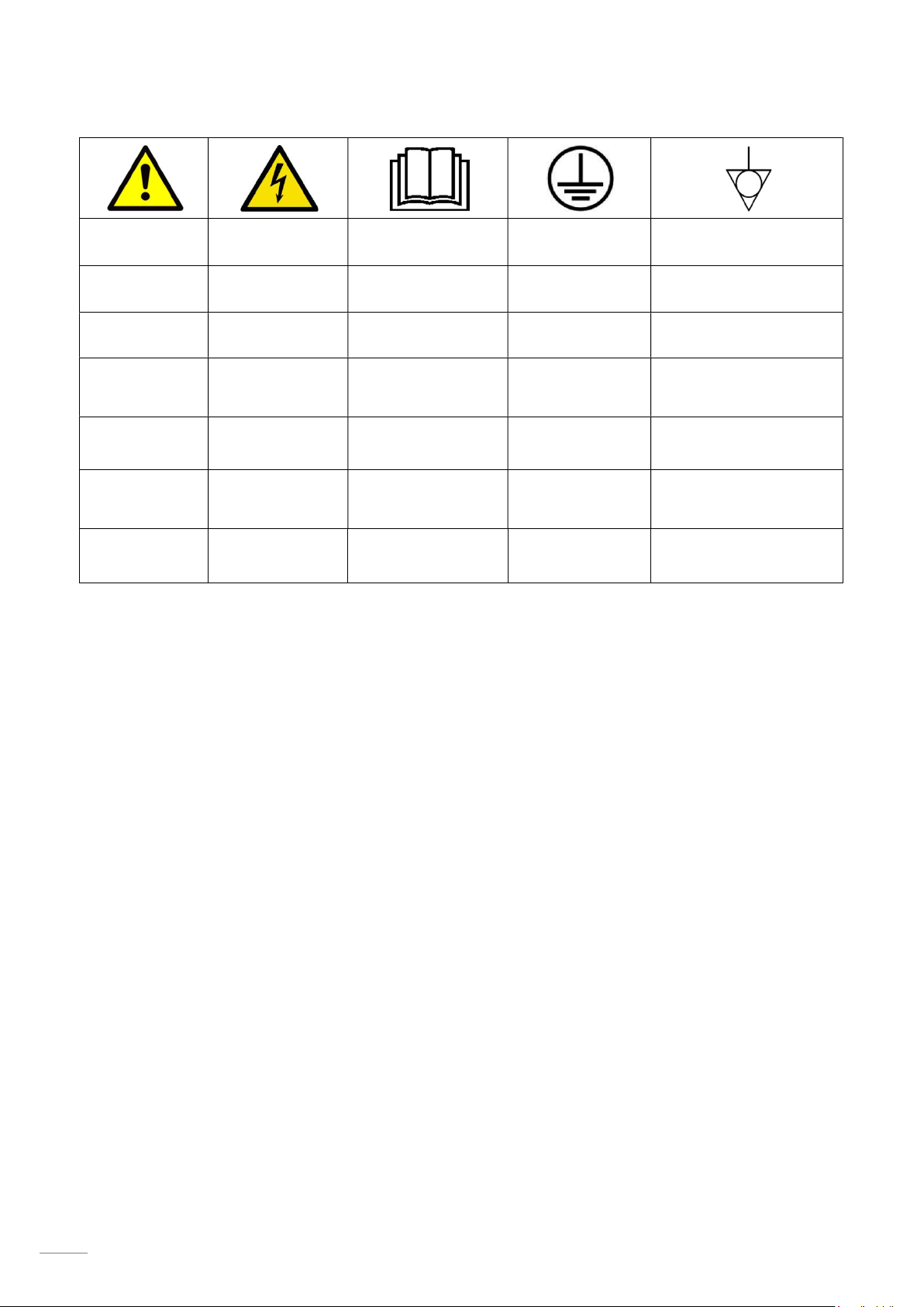
PRECAUCIÓN
TENSIÓN
PELIGROSA
LEA LAS
INSTRUCCIONES
TIERRA DE
PROTECCIÓN
EQUIPOTENCIALIDAD
PRÉCAUTION
WARNING
VORSICHT
PRECAUZIONE
OSTRZEŻENIE
UYARILAR
TENSION
DANGEREUSE
HAZARDOUS
VOLTAGE
GEFÄHRLICHE
SPANNUNG
TENSIONE
PERICOLOSA
WYSOKIE
NAPIĘCIE
TEHLİKELİ
GERİLİM
ESPAÑOL (LAVAVASOS)……………..……5
FRANÇAIS (LAVE-VERRES)…...…………18
ENGLISH (GLASSWASHER)………………31
LISEZ LES
INSTRUCTIONS
PLEASE READ
INSTRUCTIONS
ANLEITUNG
GRÜNDLICH
LESEN
LEGGERE LE
ISTRUZIONI
NALEŻY
PRZECZYTAĆ
INSTRUKCJĘ
LÜTFEN
TALİMATLARI
TERRE DE
PROTECTION
PROTECTIVE
EARTH
ÉQUIPOTENTIALITÉ
EQUIPOTENTIAL
BONDING
SCHUTZ- ERDE POTENZIALAUSGLEICH
TERRA DI
PROTEZIONE
UZIEMIENIE
OCHRONNE
TOPRAK
KORUMASI
EQUIPOTENZIALITÀ
PODŁĄCZENIE
EKWIPOTENCJALNE
EŞ POTANSİYELLİ
BAĞLANTI
DEUTSCH (GLÄSERSPÜLER)…………....44
ITALIANO (LAVAVABICCHIERI)……….....58
POLSKI (ZMYWARKI DO SZKŁA)………..71
TÜRKÇE (BARDAK YIKAMA MAKİNESİ)……86
2
Page 3
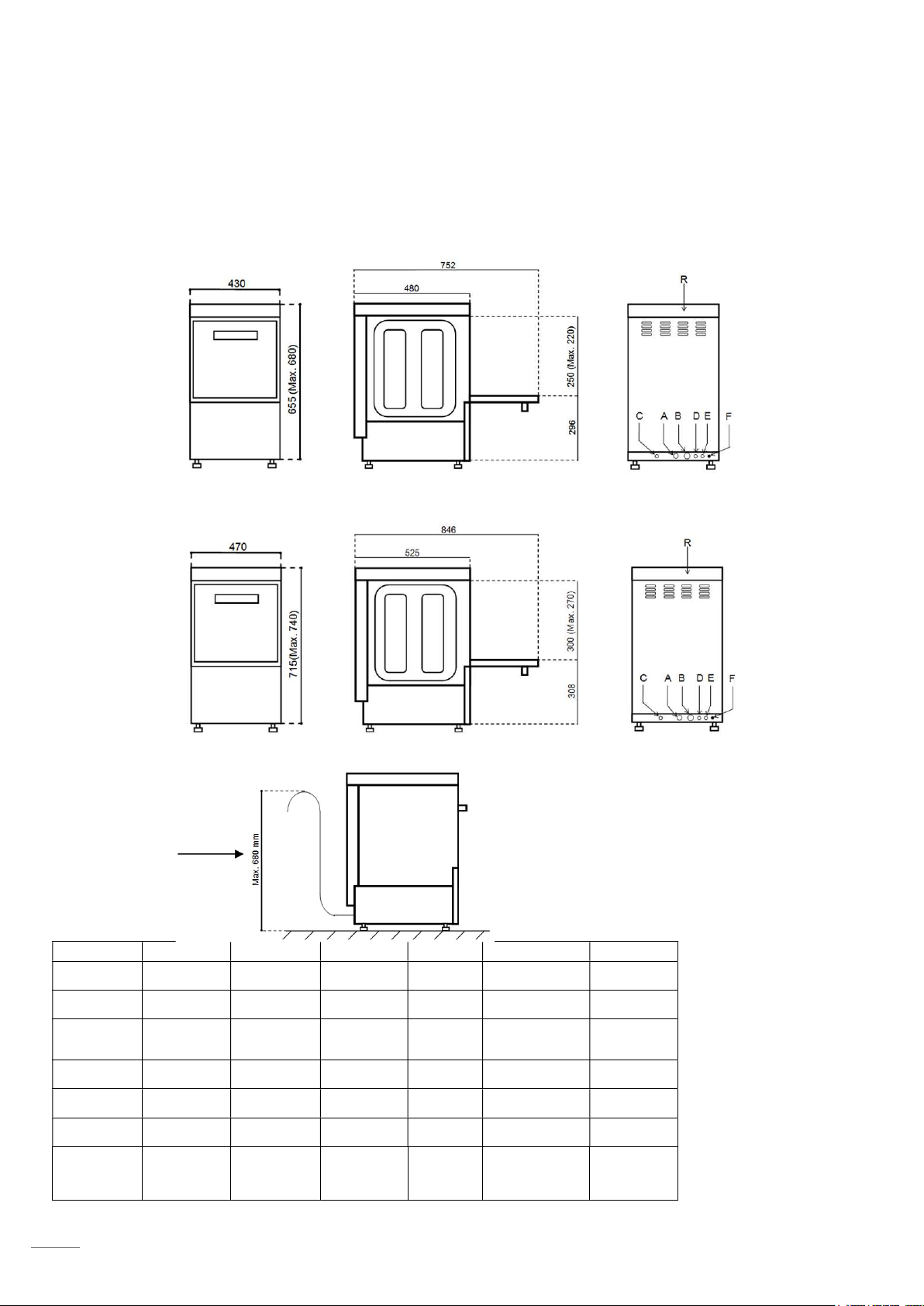
DIMENSIONES GENERALES Y ACOMETIDAS (mm) WYMIARY OGÓLNE I PODŁĄCZENIA (mm)
Fig. 1
DIMENSIONS GÉNÉRALES ET BRANCHEMENTS (mm) GENEL ÖLÇÜLER VE BAĞLANTILAR (mm)
GENERAL MEASUREMENTS AND CONNECTIONS (mm)
ALLGEMEINE ABMESSUNGEN UND ZULEITUNGEN (mm)
DIMENSIONI GENERALI E CONNESSIONI (mm)
T-OEM-350
T-OEM-400
A
Toma de agua
Prise d’eau Tuyau vidange
Water inlet Drain hose
Wasseran
schluß
Presa dácqua
Doprowadzenie
wody
SU GİRİŞİ
B C
Manguera
Desagüe
Schlauch
Wasserauslauf
Tubo di
scarico
Wąż spustowy
Tahliye
hortumu
Manguera
eléctrica
Gaine
électrique
Power Supply
Cable Strain
Relief
Kabelschlauch
Cavo elettrico
Przewód
elektryczny
Güç Besleme
Kablosu
Gerginlik
Önleyici
D E
Entrada
Abrillantador
Lustrant
entrée
Rinse aid inlet
Klarspülmittel
einlass
Entrata
brillantante
wlot element
płukającego
G
Entrada
detergente
Détergent
Entrée
Detergent
Inlet
Spülmittel
einlass
Entrada
detersivo
wlot
deteregentu
Equipotencial
Équipotentialité
Equipotential bond
Potentialausgleich
Equipotenziale
Ekwiptencjalnie
R
Regleta
conexión
Réglette
raccordement
Terminal Box
Anschlußleiste
Morsettiera
Listwa
zaciskowa
Terminal
Kutusu
Instalación con Motobomba
desagüe
Installation avec Motopompe
vidange
Installation with drainage
motor pump
Installation mit
motorbetätigter
Abfußpumpe
Impianto con motopompa di
scarico
Instalacja z pompą spustową
Motorlu tahliye pompası ile
kurulum
3
Page 4
230V 1N
A
E B D
F
G I J
A E
B
D
F G I J
Fig. 7
Fig. 2 Fig. 3
Fig. 4 Fig. 5
Fig. 6
a = azul / bleu / blue / blau / blu/ niebieski/
mavi/
m = marrón / brown / braun / marrone/ brąz/
kahverengi
r = rojo / rouge / red / rot / rosso/ czerwony/
kırmızı
n = negro / noir / black / Schwarz / nero/
czarny/ siyah
4
T-OEM-350,
T-OEM-400
Page 5
T-OEM
-350
31
Page 6
32
EN
T-OEM-400
Page 7

1. INDEX
1. INDEX ...................................................................................................................................................... 33
2. GENERAL INFORMATION AND WARNINGS ........................................................................................ 34
3. PRODUCT DETAILS ............................................................................................................................... 35
3.1 General specifications ..................................................................................................................... 35
3.2 Specific characteristics .................................................................................................................... 35
4. INSTALLATION INSTRUCTIONS ........................................................................................................... 36
4.1 Removal of packaging ..................................................................................................................... 36
4.2 Positioning and levelling .................................................................................................................. 36
4.3 Electrical connection ........................................................................................................................ 36
4.3.1 Electrical specifications of the installation ............................................................................... 37
4.3.2 Voltage Configuration of the machine ..................................................................................... 37
4.4 Hydraulic connection ....................................................................................................................... 37
4.5 Drainage connection ........................................................................................................................ 37
4.6 Mechanical rinse aid dispenser (only T-OEM-400 MOD. and versions) ......................................... 38
4.7 Electric rinse aid dispenser (only T-OEM-350 DD MOD.) ................. ¡Error! Marcador no definido.
4.8 Detergent dispenser (Optional) ....................................................................................................... 38
4.9 Pressure pump ................................................................................................................................ 38
4.10 Recycling ......................................................................................................................................... 38
5. USE AND MAINTENANCE INSTRUCTIONS ......................................................................................... 39
5.1 Operation ......................................................................................................................................... 39
5.1.1 Control panel symbols Fig. 9 ................................................................................................... 39
5.1.2 Switching on the machine ........................................................................................................ 39
5.1.3 Filling and heating .................................................................................................................... 39
5.1.4 Preparation of the dishes ......................................................................................................... 39
5.1.5 Selecting the wash cycle ......................................................................................................... 40
5.1.6 Thermo-stop ............................................................................................................................. 40
5.1.7 Stopping the wash cycle and end of wash cycle ..................................................................... 40
5.1.8 Drainage of the machine .......................................................................................................... 40
5.1.9 Switching off the machine ........................................................................................................ 40
5.1.10 Cleaning the machine at the end of the day ............................................................................ 40
5.2 Useful tips ........................................................................................................................................ 40
5.2.1 Maintenance ............................................................................................................................ 40
5.2.2 Rinse aid and detergent ........................................................................................................... 41
5.2.3 Hygiene regulations ................................................................................................................. 41
5.2.4 Optimum results ....................................................................................................................... 41
5.2.5 Prolonged non use ................................................................................................................... 41
6. FAULTS, ALARMS AND BREAKDOWNS .............................................................................................. 42
6.1 Errors shown in display .................................................................................................................... 43
7. RECYCLING THE PRODUCT ................................................................................................................. 43
33
Page 8
EN
2. GENERAL INFORMATION AND WARNINGS
This manual has been created to help you understand the operation, installation and maintenance of the
machine. It contains all the necessary information and warnings to ensure that the appliance is installed and
used correctly, together with information about the characteristics and possibilities offered, so that you may
enjoy your machine to the full.
BEFORE STARTING THE APPLIANCE, PLEASE READ THE INSTRUCTIONS CONTAINED
IN THIS MANUAL CAREFULLY.
The manual should be kept safely to hand for future reference.
If the machine is sold or transferred, please pass the manual to the new user.
THIS APPLIANCE IS EXCLUSIVELY FOR PROFESSIONAL USE, AND SHOULD ONLY BE
USED BY QUALIFIED PERSONNEL.
The positioning and installation, and all repairs or modifications, should always be carried out by an
AUTHORISED TECHNICIAN, in accordance with the applicable legislation of the country. The
manufacturer does not accept liability if the machine is incorrectly installed.
The installation, incorrect adjustment, inappropriate maintenance or use of the appliance may cause
material damages and injuries.
The dishwasher should be correctly levelled and care taken to ensure that none of the electric cables,
water or drainage hoses are trapped or kinked.
DO NOT climb on top of the dishwasher or place heavy objects on top of the machine as it has only
been designed to bear the weight of the basket of plates to be washed.
The dishwasher is designed for washing plates, glasses and other kitchenware with traces of
human food. Any other objects must not be washed in the machine.
If your machine breaks down, please call the Technical Service Centre.
Unqualified or unauthorised personnel must NOT try to repair the machine.
Use of spare parts other than original parts will cancel the guarantee.
During all maintenance operations, the dishwasher must be disconnected from the main power
supply at the mains power switch, and the water intake tap must be closed.
Abrasive or corrosive products, acids, solvents and chlorine-based detergents must NOT be
used to clean the appliance, as this may damage the components.
This appliance has been designed for use in ambient temperatures between 5 ⁰C and 40 ⁰C.
Only the baskets, soaps and rinse aids recommended by the manufacturer should be used.
FAILURE TO COMPLY WITH THESE INSTRUCTIONS OR THE INCORRECT USE OF THE
APPLIANCE SHALL RELIEVE THE MANUFACTURER OF ANY OBLIGATIONS
REGARDING THE GUARANTEE OR POSSIBLE CLAIMS.
34
Page 9
3. PRODUCT DETAILS
SERIAL NUMBER + MANUFACTURE
The machine which you have just purchased is specially designed for cleaning tableware, glassware and
other items of kitchenware, used in the hotel and catering sector. As it is an industrial product, it is
characterised for having a high dishwashing capacity.
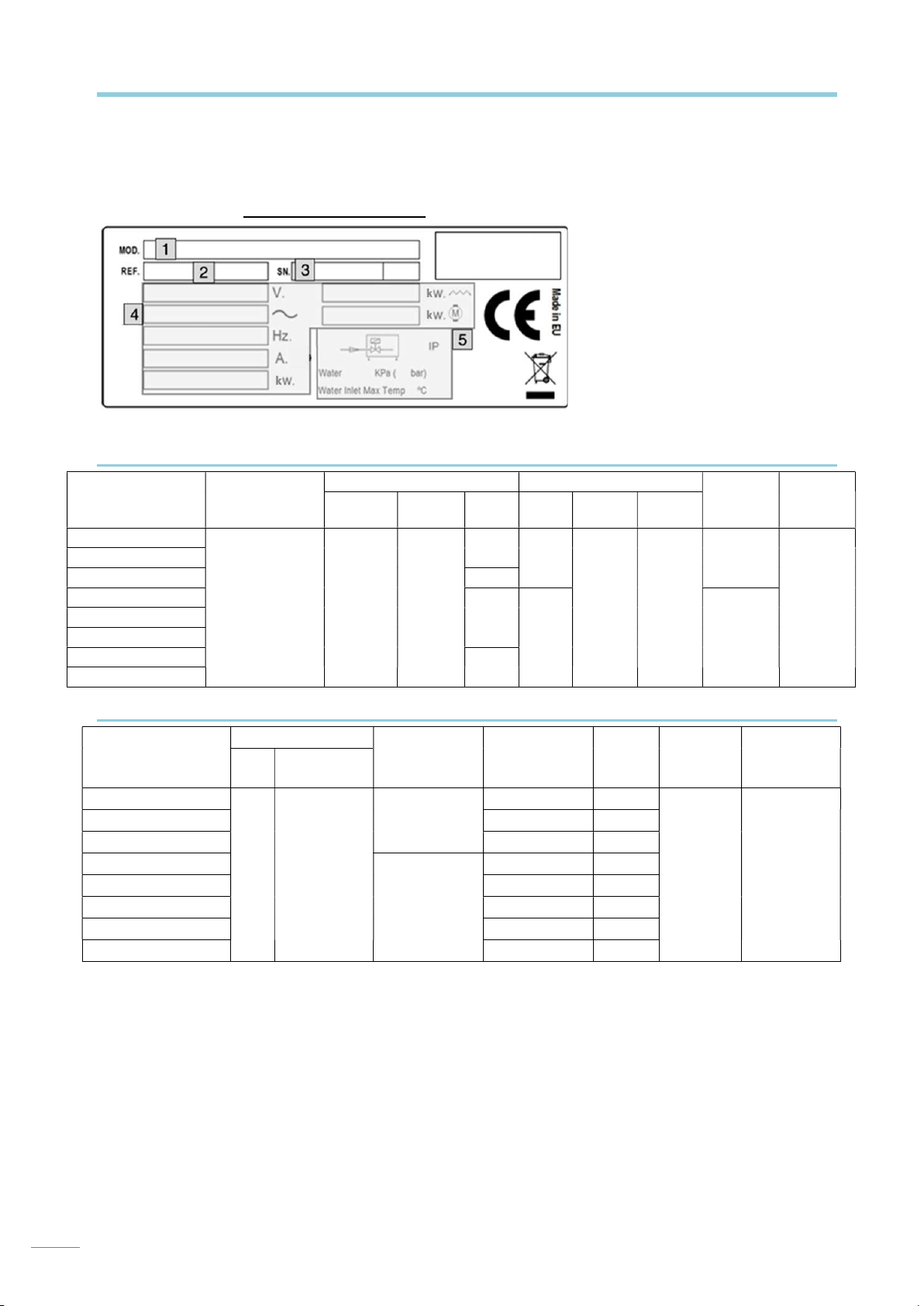
All the appliances have a specifications plate which identifies the appliance and indicates its technical
characteristics, it is located on one side of the machine. Don`t remove the specifications plate from the unit.
SPECIFICATIONS PLATE
1: APPLIANCE MODEL NAME
2: APPLIANCE REFERENCE
3:
4: ELECTRICAL SPECIFICATIONS
5: WATER INLET SPECIFICATIONS
These details should be quoted when the technical service is called.
3.1 General specifications
DATE
MOD.
T-OEM-350
T-OEM-350 DD
T-OEM-350 UK 2400
T-OEM-400
T-OEM-400 DD
T-OEM-400 B
T-OEM-400 UK
T-OEM-400 UK B
VOLTAGE
SUPPLY
230V 1N 50Hz
230V 1N 60Hz
CAP. TEMP.
BOILER RÉSERVOIR
5 l 85 ºC
POW.
(W)
2400
2800
2400
CAP. TEMP.
11 l
15 l 2,5
60 ºC 2000
3.2 Specific characteristics
WASH CYCLES
MOD.
Nº
LENGTH
(s)
COLD RINSE
T-OEM-350
T-OEM-350 DD - YES
T-OEM-350 UK - T-OEM-400
T-OEM-400 DD - YES
T-OEM-400 B YES -
3
90 / 120 /
180
YES
T-OEM-400 UK - T-OEM-400 UK B YES -
DRAINAGE
PUMP
- -
- -
DETG.
DOSE.
WATER
POW.
(W)
CONS.
(l/cycle)
THERMO
STOP
YES 30
Sound
Level
2
65 dBA
WASH
CAPACITY
(baskets/h
35
Page 10
EN
4. INSTALLATION INSTRUCTIONS
The positioning and installation, and all repairs or modifications,
should always be carried out by an AUTHORISED TECHNICIAN,
in accordance with the applicable legislation of the country.
The installation, incorrect adjustment, inappropriate maintenance or use of
the appliance may cause material damages and injuries.
4.1 Removal of packaging
Remove packaging from the machine and check for damage during transportation. If any damage is
observed, immediately notify the supplier and the transport company. In the event of doubt, do not
use the machine until the problem has been assessed.
Packaging (plastic, expanded polyurethane, staples, etc…) must not be left in the
reach of children, they are a potential hazard.
The machine should be moved using a fork-lift truck or similar to avoid damage to the structure.
Transport the machine to the installation location and then remove packaging.
All the packaging can be recycled. Dispose of packaging correctly.
4.2 Positioning and levelling
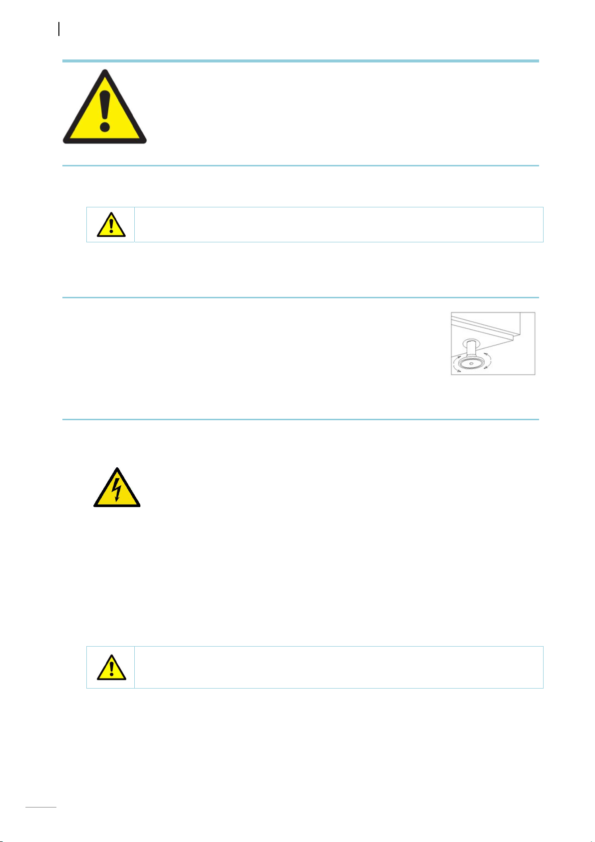
This appliance has adjustable feet to allow it to be adjusted to the correct
height, this is done by turning the foot to the desired height. For optimum
operation, it is essential that the machine is correctly levelled. The flooring on
which the machine is to be installed must be able to bear the full weight of the
machine.
Inspect final location of the machine prior to installation to prevent
damage during use.
4.3 Electrical connection
An AUTHORISED TECHNICIAN should always carry out the appliance’s electrical connection.
The legal standards in force in each country regarding connection to the mains should be taken into
account.
Check that the mains voltage corresponds to that indicated on the nameplate.
The electric cable should be flexible, with an oil-proof covering, and it should not
weigh less than the cable in an ordinary sleeve made of standard polychloroprene
or an equivalent synthetic elastomer (H07RN-F ).
The cross-section of the power cable must be suitable for the rated current of the
machine.
An easily accessible switch device should be installed next to the appliance for all
the phases, with a minimum gap of 3 mm between contacts. This switch should be
used to disconnect the appliance during installation, repair, cleaning and
maintenance work. The switch should have fuses suitable for use with the rated
current (A) of the machine. Alternatively, a suitable magneto-thermal switch may be
used.
The appliance must be earthed using a differential protector. The manufacturer will
not be held liable for damage originated by failure to observe this requirement.
If any faults are observed during the installation, the supplier should be notified immediately.
The manufacturer will not be held liable for any personal or material damage to the
machine resulting from incorrect installation or failure to comply with the
manufacturer’s specifications.
36
Page 11
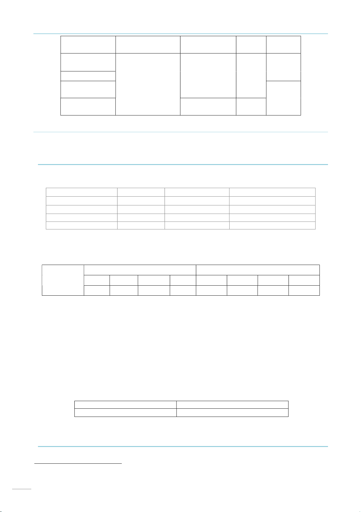
4.3.1 Electrical specifications of the installation
MOD.
SUPPLY
VOLTAGE
MAX ELECTRIC
POWER
AMP.
(A)
T-OEM-350
(DD)
T-OEM-350 UK
T-OEM-400
2,7 kW
230V 1N~ 50/60Hz
11,6 A
(UK / UK B)
T-OEM-400
(DD / B)
3,1 kW 13,3 A
4.3.2 Voltage Configuration of the machine
The voltage configuration of the machine is stipulated on the nameplate (230V 1N~50Hz/60Hz). This
configuration cannot be changed, therefore it is essential that the mains voltage of the premises
where the machine is to be installed is confirmed prior to purchase. Fig. 6
4.4 Hydraulic connection
The new hoses supplied with the appliance should be used (do not reuse old hoses).
Before connecting the machine to the water supply, the water quality should be tested.
Recommended water quality:
Water temperature (T): max. 60 ⁰C Total water hardness: 5 – 10 ⁰fH (French degrees)
pH: 6.5 - 7.5 7 – 14 ⁰eH (English degrees)
Impurities: Ø < 0.08 mm
Chlorides: max. 150 mg/l Conductivity: 400 - 1,000 µS/cm
Cl: 0.2 - 0.5 mg/l
If the water hardness is more than 10 ⁰fH (French degrees), a descaler must be installed.
In addition to water quality, the pressure of the mains water supply must be considered. This is
important to ensure the machine operates correctly.
Required water pressure:
9 – 18 ⁰dH (German degrees)
NET
WEIGHT
34 kg
41 kg
Min. Max.
DYNAMIC bar kPa kg/cm
PRESSURE 2 200 2,03 29 3,5 350 3,56 50,76
2
psi bar kPa kg/cm
2
psi
If the water pressure is higher than the recommended pressure, a pressure regulator must be
mounted at the output Fig. 2. If the mains water pressure is lower than the recommended pressure,
a pressure pump should be mounted at the mains water supply Fig. 3. It is not necessary to install a
pressure pump in the W models.
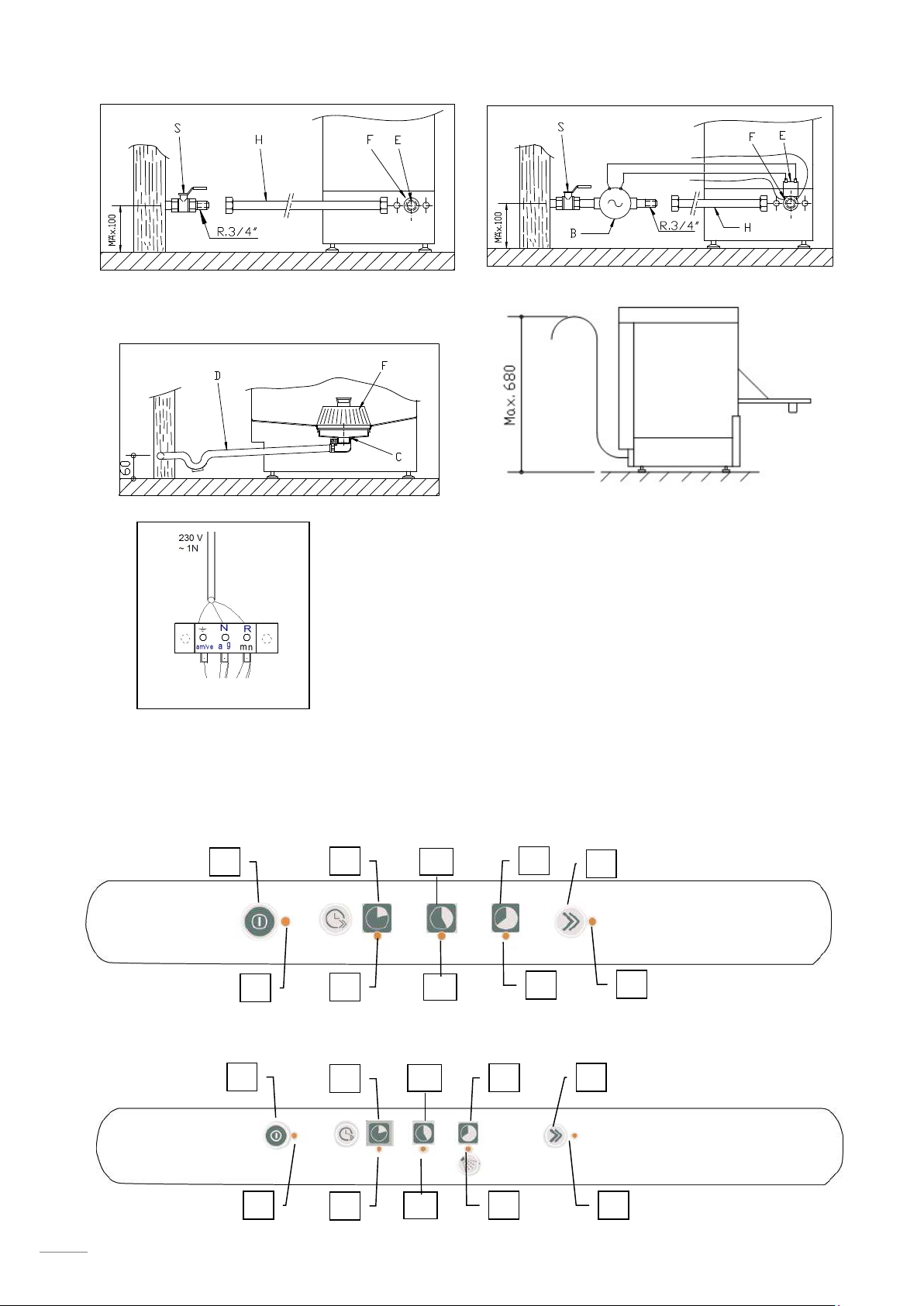
Fig. 2. Direct connection of water input hose.
Fig. 3. Pressure pump connection.
S → SHUT-OFF COCK F → FILTER H → WATER HOSE5
E → ELECTROVALVE B → ELECTRIC PRESSURE PUMP
The following requirements are necessary for the correct hydraulic installation of the machine.
The hydraulic circuit must be fitted with a valve to shut-off the water supply.
Check that the mains pressure is within the range indicated above.
To optimise the working of the machine, the manufacturer recommends that the water
temperature at the machine intake is within the following range.
Cold H2O Hot H2O
5 ⁰C < Tª < 25 ⁰C / 41 ⁰F < Tª < 95 ⁰F 40 ⁰C < Tª ≤ 60 ⁰C / 122 ⁰F < Tª < 140 ⁰F
If using hot water, the water temperature must not exceed 60 ⁰C / 140 ⁰F.
All the machines should have a ¾” screw-on connection.
4.5 Drainage connection
5
For Australia, watermark certified inlet hose and backflow prevention device. Must be installed in
accordance with AS/NZS3500.1 (water service supply) including installation of the supplied backflow
prevention device.
37
Page 12
EN
The water draining from the machine must flow freely and therefore the drainage pipe should be
lower than the drainage outlet Fig. 4. If the drainage pipe is not lower, a drainage pump will be
required. This must not be mounted at a height of more than 680 mm Fig. 5. In this case, the pump
may be requested at the time of purchase or subsequently.
Fig. 4. Drainage installation. 6
Fig. 5. Installation of drainage at a height using drainage pump.
The drainage pump must only be installed by personnel authorised by the
manufacturer, and the manufacturer does not accept liability in the event of
incorrect installation.
4.6 Mechanical rinse aid dispenser (only T-OEM-400 MOD. and versions)
Operation: This dispenser absorbs the rinse aid when it detects a loss in pressure during rinsing.
That is, when the filling solenoid valve closes, a vacuum is created that makes the rinse aid
dispenser absorb the fluid to which it is connected.
Adjustment: The dispenser should be adjusted when the machine is installed to ensure that the
wash is optimised from the start. The setting should be adjusted according to the type of rinse aid
and the water hardness.
4.7 Detergent dispenser (Optional)
This ensures that the correct measure of detergent is supplied to the machine.
Installation: the detergent dispenser input must be in the tub of the machine, below the maximum
water level. Please see the electrical circuit diagram for details of the electrical connection The tub
has an opening for the installation of the dispenser.
Operation: the detergent dispenser is activated when the machine is taking water, whether it is in
rinse cycle or whether it is filling.
Settings: the measure of detergent used should be adjusted when the component is installed to
ensure that the wash is optimised from the start.
The manufacturer that the detergent and the dispenser setting are defined
by a technician specialised in the use of chemical products in order to
ensure a more efficient wash.
4.8 Pressure pump
If the mains water pressure is less than 2 bar (200 kPa), you have the option of installing a pressure
pump. If the pressure is less than 2 bar (200kPa), the machine may operate incorrectly. The
electrical connections for the pressure pump are shown in the electric circuit diagram. The water
connection to the pressure pump is shown in Fig. 3.
If the mains water pressure is less than 2 bar (200 kPa), please contact your supplier or the
manufacturer to request the PRESSURE PUMP KIT.
The pressure pump must only be installed by personnel authorised by the manufacturer,
and the manufacturer does not accept liability in the event of incorrect installation.
4.9 Recycling
The product packaging consists of:
A wooden pallet.
Cardboard.
A polypropylene band.
Expanded polyethylene.
All the packaging used around the machine can be recycled; The correct disposal of these products
will help to protect the environment. For further information regarding the recycling of these products,
please refer to the relevant office of the local body. Dispose of these materials in accordance with
current legislation.
6
31mm in diameter and must be installed in accordance with AS/ NZ3500.2 (drainage) by means of coupled
connection to a DN40 or larger pipe
38
Page 13
5. USE AND MAINTENANCE INSTRUCTIONS
BEFORE STARTING THE APPLIANCE, PLEASE READ THE INSTRUCTIONS
THE APPLIANCE IS EXCLUSIVELY FOR PROFESSIONAL USE, AND SHOULD
5.1 Operation
The steps required to optimise the operation of your dishwasher are shown below, with all the available
options.
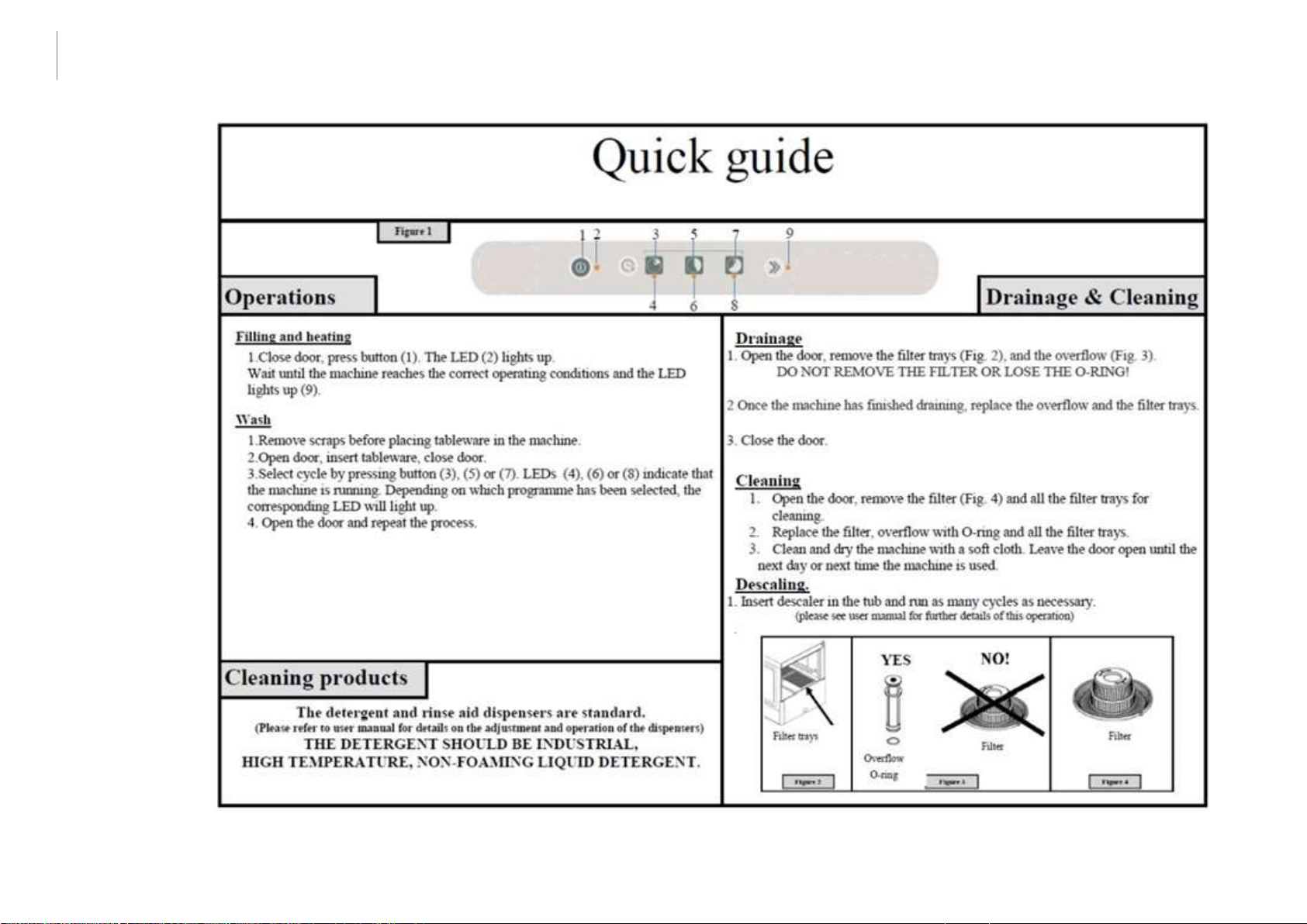
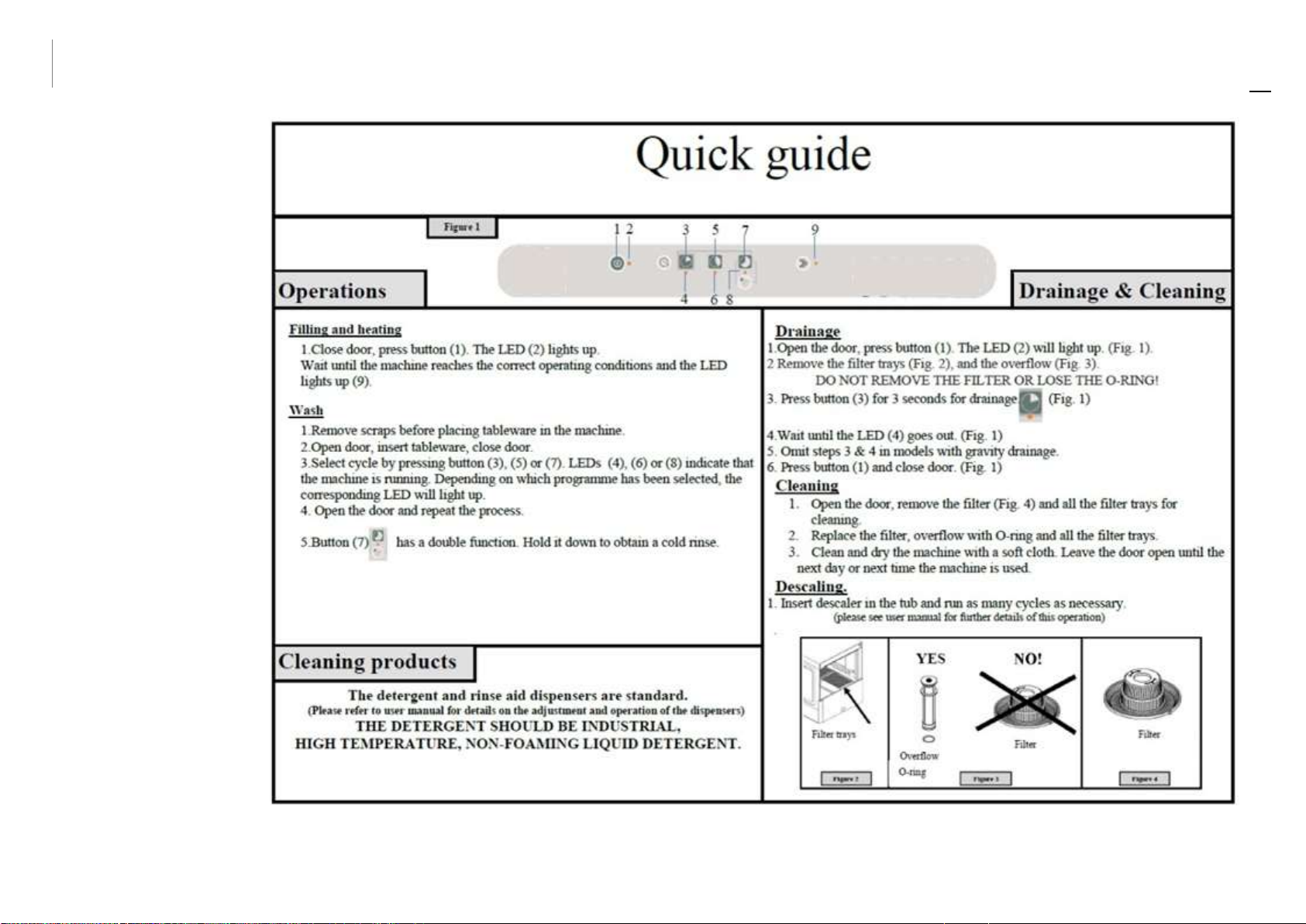
5.1.1 Control panel symbols Fig. 9
A. Machine on/off button. (ON/OFF) F. Machine on pilot light
B. Short cycle button (90 s)/ Drainage button G. Machine working pilot
C. Medium cycle button (120 s) H. Machine working pilot
D. Long cycle button (180 s) / Cold rinse button I. Machine working pilot
E. Machine ready symbol J. Machine ready pilot
5.1.2 Switching on the machine
Before switching on the machine, check the following:
The mains switch must be on.
The water stop cock must be open.
There must be water in the mains network.
The corresponding filters must be in place.
The overflow should be mounted in place.
To switch on the machine just press the ON-OFF button (A) once for 1.5 seconds.
5.1.3 Filling and heating
When the machine is switched on, it will start to fill. First the rinse boiler is filled and then the wash
tub. The filling process may last a few minutes. Once the wash tub is full, the boiler starts to heat up
and when it is hot, the tub is heated. Although it is possible to start the wash process, this is not
recommended as the water inside the machine is not yet at the ideal temperature. When the
machine has reached the ideal temperature for washing the dishes properly, the machine ready light
CONTAINED IN THIS MANUAL CAREFULLY.
ONLY BE USED BY QUALIFIED PERSONNEL.
comes on.
The temperature in the boiler should be between 82-90 ºC and in the tank between 57-62 ºC
The manufacturer recommends that the water in the glass washer is changed every 40/50 washes or
twice a day.
The door must be closed for the machine to start filling. For safety reasons, if the
door is open, the machine will not fill.
The machine you have purchased has a safety thermostat in the boiler and another for the tub, so
that in the event of the breakdown of any of the main thermostats, the safety thermostats switch off
the corresponding heating.
During the first heating of the day, the boiler may reach a higher temperature than
that mentioned above due to heating inertia. This is normal. If pressurised steam is
observed coming out of the rinse branch nozzles, while the boiler is heating, the
technical service should be notified.
5.1.4 Preparation of the dishes
Before washing the dishes, the preparatory steps below should be followed:
Remove the largest pieces of waste from the dishes before placing them in the baskets.
Wash glassware first.
Put the plates in the rack basket.
Place the glasses upside down.
Place the cutlery in the cutlery baskets with the handles downwards. The different pieces of
cutlery can be mixed.
Place the cutlery baskets in the lower baskets.
39
Page 14
EN
5.1.5 Selecting the wash cycle
Before starting the wash cycle, place the corresponding basket containing the dishes in the machine.
To start the wash process first close the door and then select the wash cycle you wish to run for 1.5
s. The wash cycle will start automatically. Each wash cycle runs for a set time that is selected
according to how dirty the plates are (90 s/120 s/180 s).
The door must be closed for the machine to start the wash cycle. For safety reasons,
if the door is open, the wash cycle will not start.
5.1.6 Thermo-stop
The thermo-stop guarantees a constant rinse at a temperature of 85 ⁰C. This means that the
machine continues washing until the boiler reaches the ideal temperature. Then the rinse cycle
starts.
5.1.7 Stopping the wash cycle and end of wash cycle
The wash cycle can be stopped in the following ways:
By switching off the machine → the cycle stops completely.
By opening the door → when the door is closed, the cycle continues.
At the end of the wash cycle, remove the basket and leave the dishes to dry naturally. Remove the
dishes from the basket with clean hands, taking care not to burn yourself as the dishes are extremely
hot.
5.1.8 Cold rinse (only T-OEM-400 MOD. and versions)
The machine you have purchased has a cold rinse system so that once the tableware has been
washed, it can be cooled quickly ready for subsequent use. To activate the cold rinse system, turn
the control button to cold rinse (D) and hold down for the required time.
5.1.9 Drainage of the machine
The dishwashers have two types of drainage; gravity drainage or using a drainage pump.
5.1.9.1 Drainage by gravity
To drain the machine in this way, just remove the overflow from the machine and it will drain
naturally. For reasons of safety, this method of drainage should only be used with the machine
switched off.
5.1.9.2 Drainage using the drainage pump (optional)
The drainage using the drainage pump option is only available on request. The drainage pipe must
always be fitted on a siphon to prevent the return of odours.To drain the machine using this method,
proceed as follows:
Remove the overflow valve.
Leave the door open.
Press the drain button (B) for 3 seconds and the drainage cycle will start automatically.
At the end of the cycle (approx. 160 s), replace the overflow valve. The machine may be
switched off.
To drain the machine with the drainage pump, the hose must be at a
height (max. 680 mm).
5.1.10 Switching off the machine
The dishwasher is switched off by pressing the ON-OFF button for 1.5 s.
The machine should not be switched off during the wash process as this will stop the tableware
inside the machine from being cleaned properly.
5.1.11 Cleaning the machine at the end of the day
At the end of the day, the filters, wash distributors, rinse branches and other accessories must be
cleaned. This is necessary to prolong the service life of the machine. To ensure the efficient washing
of the dishes, the dishwasher must be perfectly clean and disinfected.
5.2 Useful tips
Read the useful tips listed below carefully to allow you to get the most out of your dishwasher.
5.2.1 Maintenance
Always clean the machine correctly to prolong the service life of the machine.
Remove any waste from the machine at the end of each day.
40
Page 15

Do not use abrasive, corrosive or acid products, chlorine-based detergents, solvents or
petrol derivatives to clean the machine.
Do not use pressurised water to clean the machine.
Only wash tableware, glassware or kitchenware that has been used for human food.
Check that the wash distributors rotate correctly every day.
Check the salt, rinse aid and detergent levels at the start of each day.
Call the technical service twice a year to have the machine serviced:
o Cleaning of water filter.
o Cleaning of limescale on the resistors.
o Inspection of the condition of the seals.
o Inspection of the condition of the parts.
o Adjustment of the dispensers.
o Tightening of the electrical connections on the terminals.
If the power cable is damaged, it must be replaced by the manufacturer, after-sales service or
authorised technical personnel in order to prevent risks.
5.2.2 Rinse aid and detergent
If you change the rinse aid or detergent, the settings should be adjusted accordingly. This
adjustment must be carried out by qualified personnel. Only use detergents suitable for industrial
dishwashers. Do not use foam-producing detergents. Detergents designed for domestic use should
not be used under any circumstances.
When handling chemical substances, the safety instructions must be observed. Use
suitable protective clothing, gloves and safety goggles when handling chemical
substances. Do not mix different detergents.
5.2.3 Hygiene regulations
Do not touch clean dishes with dirty or greasy hands.
Use clean sterilised cloths to thoroughly dry the dishes.
We recommend you wait until the machine reaches the correct wash temperature as this will
ensure a more thorough disinfection and wash.
Drain the wash tub at least twice a day or every 40/50 wash cycles.
5.2.4 Optimum results
To obtain optimum dishwashing results, the manufacturer recommends you proceed as follows:
Wash the dishes when the machine is ready.
Always ensure the different dispensers are correctly adjusted.
Keep the dishwasher thoroughly clean.
5.2.5 Prolonged non use
If the machine is kept out of service for a long period of time (holidays, temporary closure…), please
observe the following:
Drain the machine completely, including the boiler.
Clean the machine thoroughly.
Leave the door of the machine open.
Close the water intake valve.
Switch off the mains power supply.
If there is a risk of frosts, ask your technical service to protect the machine against frosts.
41
Page 16
EN
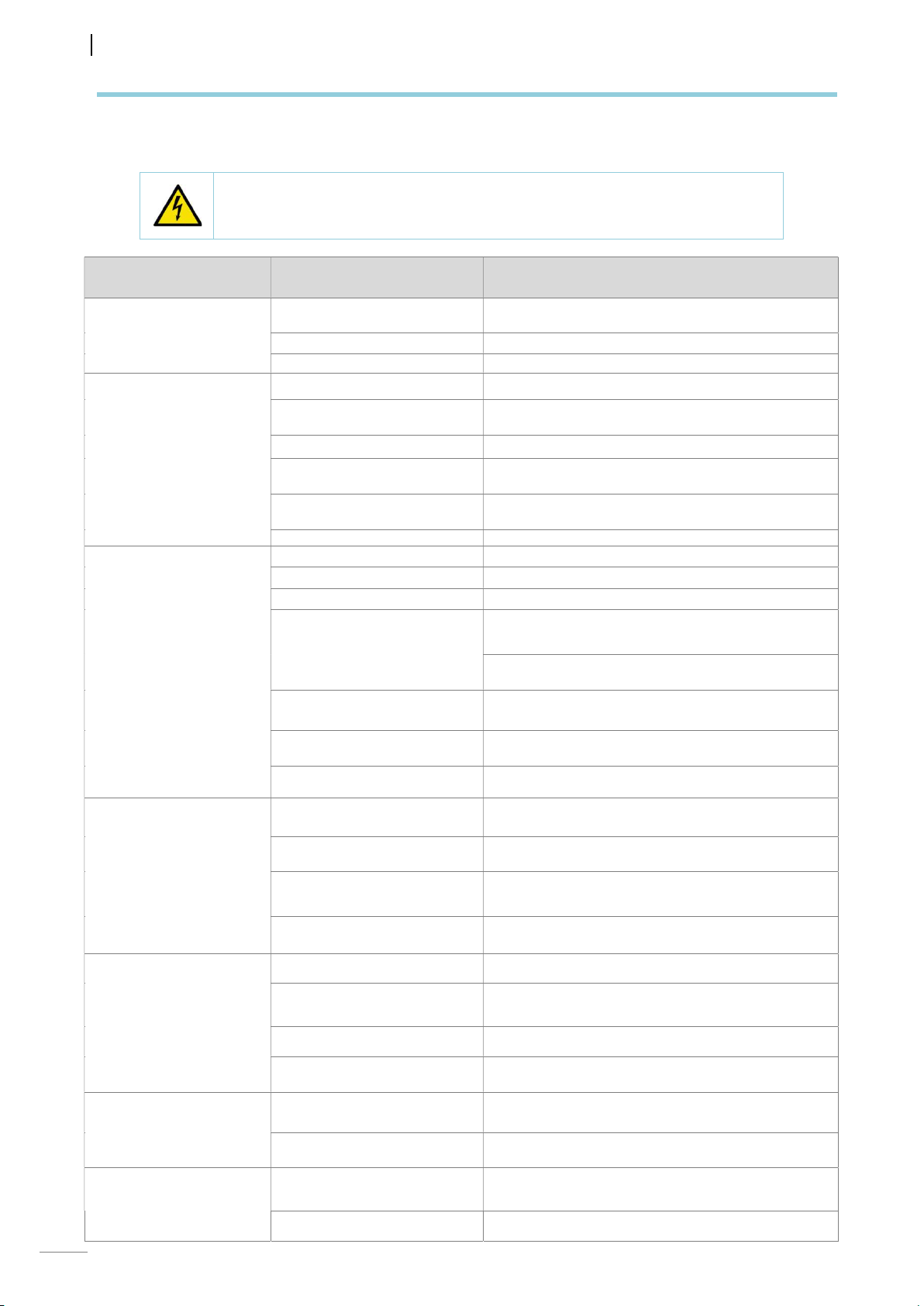
6. FAULTS, ALARMS AND BREAKDOWNS
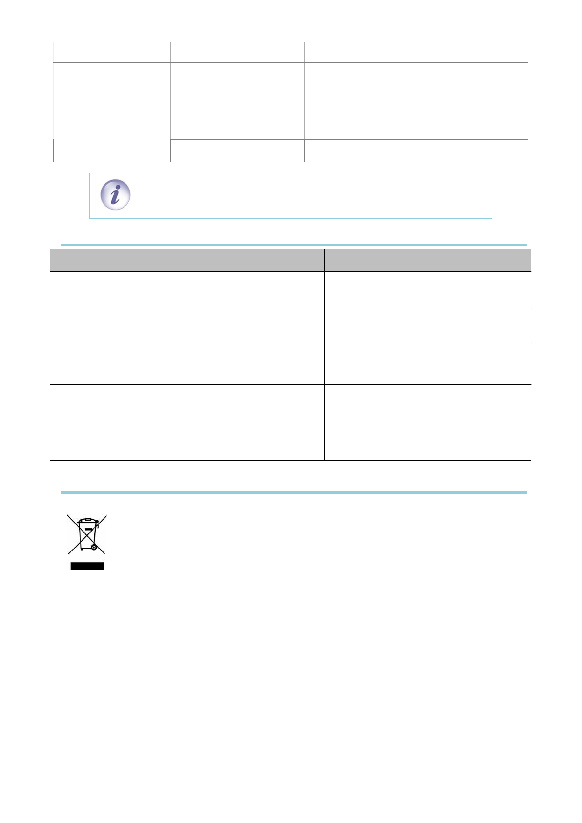
The steps to be followed in the event of a fault or operating error are described below. The possible causes
and possible solutions are listed in the following table. In the event of doubt, or if you are unable to resolve
the problem, please contact the technical service.
Do not handle electrical components, as there is a risk of death as the
components are live.
FAULT POSSIBLE CAUSE SOLUTION
The machine does not
come on.
The machine does not fill
with water.
Unsatisfactory wash.
There is no power supply.
The fuses have blown. Call the technical service to analyse the reason why.
Main switch open. Close switch.
Water entrance valve closed. Open the water valve.
Rinse nozzles blocked.
Solenoid valve filter blocked. Call the technical service to clean the filter.
Rinse pump faulty
Pressostat is broken.
Door is not closed properly Close the door properly.
Wash distributors obstructed. Clean distributors thoroughly.
Shortage of detergent. Call the technical service to reset the dispenser.
Dirty filters. Clean the filters thoroughly.
Presence of foam.
Temperature of lower tub at 50
⁰C / 122 ⁰F.
Length of cycle too short for
level of dirt on dishes.
Water too dirty. Drain the wash tub and fill with clean water.
Check whether the magneto-thermal circuit breaker
has been triggered.
Clean nozzles and check branches for build-up of
lime.
Call the technical service to replace the pressure
switch.
Call the technical service to replace the pressure
switch.
Unsuitable detergent. Call the technical service to
supply correct detergent.
Too much rinse aid. Call the technical service to reset
the dispenser.
Thermostat faulty or incorrectly set. Call the technical
service to repair it.
Select a longer cycle.
Dishes and kitchenware
are not dry.
Scratches or stains on
dishes.
Machine stops during
operation.
Machine stops and fills
with water when it is
washing.
42
There is no rinse aid Fill the rinse aid container.
Rinse aid low. Call technical service to adjust dispenser.
Dishes left inside dishwasher
for too long.
Rinse temperature lower than
80 ⁰C / 176 ⁰F.
Too much rinse aid. Call technical service to adjust rinse aid dispenser.
Water too chalky.
Not enough salt in salt deposit. Fill salt deposit where applicable.
Traces of salt in tub.
Electrical installation
overloaded.
Machine protection has tripped.
Pressure switch pipe blocked. Empty the tub and clean thoroughly.
Pressure switch faulty. Call the technical service to replace it.
When the dishwasher finishes, remove the basket
from the machine and allow to dry naturally.
Call technical service to analyse problem.
Check water hardness and if possible run
regeneration cycle immediately.
When filling the salt deposit, take care not to spill salt
in the tub.
Call technical service to modify electrical installation.
Reset safety device and if it trips again, call technical
service.
Page 17
The machine does not
start with the wash cycle.
Overflow incorrectly mounted. Mount overflow correctly.
Close the door correctly and if it is seen to re-open
Door is not closed properly.
Door micro switch faulty. Call the technical service to replace it.
alone, call the technical services to adjust the
tensioneers.
Level the machine In the event of doubt, please
contact your technical service.
Call the technical service to replace the pressure
switch.
Machine does not drain
completely.
Machine not levelled correctly.
Pressure switch faulty.
NOTE: If a fault occurs and is not listed in the above table, please call the
technical service. The manufacturer reserves the right to modify the
technical characteristics with prior warning.
6.1 Errors shown in display
ERRORS DETECTION DENOMINATION
E1
E2
E3
E4
ON/OFF LED lights up for 0.5 s and turns off for
2 seconds, repeatedly.
ON/OFF LED lights up twice for 0.5 s each time
and turns off for 2 seconds, repeatedly.
ON/OFF LED lights up three times for 0.5 s
each time and turns off for 2 seconds,
repeatedly.
ON/OFF LED lights up four times for 0.5 s each
time and turns off for 2 seconds, repeatedly.
Door or hood is open.
Incorrect water level. Stipulated fill time
exceeded.
Incorrect drainage of the machine Stipulated
drainage time exceeded.
Incorrect boiler temperature. Stipulated boiler
heating time exceeded.
E5
ON/OFF LED lights up five times for 0.5 s each
time and turns off for 2 seconds, repeatedly.
7. RECYCLING THE PRODUCT
The European Directive 2012/19/EU relating to Waste Electrical and Electronic Equipment
(WEEE) states that household appliances should not be disposed of using the normal solid
urban waste cycle. Exhausted appliances should be collected separately in order to
optimise the cost of re-using and recycling the materials inside the machine, while
preventing potential damage to the atmosphere and to public health. The crossed-out
dustbin is marked on all products to remind the owner of their obligations regarding
separated waste collection. For more information relating to the correct disposal of
household appliances, owners should contact their local authorities or appliance dealer.
Incorrect tank temperature. Stipulated tank
heating time exceeded.
43
 Loading...