

Page 1

READ CAREFULLY THE INSTRUCTIONS
BEFORE USING THE APPLIANCE
CONVECTION+HUMIDIFICATION
COMBI DIRECT
105/110/115
ANALOGIC
EN
10/2017
CONVECTION - STEAM OVEN
INSTRUCTIONS FOR THE INSTALLATION,
USE AND MAINTENANCE
Pentland Wholesale Ltd. Blizzard House,
Unit17 Walker Industrial Estate, Walker Road.
Blackburn, Lancashire, BB1 2QE
TEL: 01254 614444
Email: [email protected]
Page 2

5 - 10 - 15 x 1/1 GN ANALOGIC
2
INDEX
Foreword
1.0
Declaration of Conformity
1.1
European Directive ROHS 2012/19/UE
1.2
Dimensions
1.3
Transport of the oven and packaging removal
1.4
Informative labels
INSTALLATION
1.5
Oven positioning
1.6
Technical data for electrical connection
1.7
Electrical connection
2.3
Water features
2.4
Technical data table water connection
2.5
Hydraulic connection – water inlet
2.6
Hydraulic connection- water drainage
3.0
Control and safety devices
3.1
Spare parts replacing
3.2
Checking the functions
USE AND MAINTENANCE
4.0
Instructions for a safe use of the oven
4.0A
Max food loading
4.1
Programming and operation Mod. Convection + Humidification
4.1A
Components description of control panel Mod. Convection + Humidification
4.2
Programming and operation Mod. Combi Direct
4.2A
Components description of control panel Mod. Combi Direct
4.4
Starting the oven
4.5
Auxiliary commands and controls
4.5A
Safety devices
4.6
Turning the oven off
9.0
Maintenance
9.0A
Cleaning of external oven parts
9.0B
Cooking chamber cleaning
9.1
What to do in the case of a breakdown and/or extended period of non use
10.0
Cooking tips
10.1
Remedies to cooking hitches
Page 3
5 - 10 - 15 x 1/1 GN ANALOGIC
3
FOREWORD
The contents of this manual are generic and not all the functions described may be available on
your product.
The manufacturer declines all responsibility for possible inaccuracies contained in this pamphlet, due to
printing or copy errors. We reserve the right to make on our own products those changes to be considered
necessary or useful, without jeopardizing the essential characteristics.
Read the instructions for use very carefully paying particular attention to the rules concerning safety devices. This appliance must only be used for what it has been designed for and built for and that is: all baking
of dishes and regenerating pre-cooked and/or frozen food.
WARNING!
Before making any type of connection of this equipment (electrical or hydraulic), carefully read the instructions in this manual.
This manual must be carefully kept to be available for future reference by
users or service technicians. Installation must be carried out by d qualified
personnel only.
1.0 DECLARATION OF CONFORMITY
The Manufacturer declares that the appliances conform to the EEC norms.
They must be installed in accordance with current standards, especially regarding aeration of the premises and the exhaust gas evacuation system.
Note: The Manufacturer declines all and every responsibility for any direct damages caused by:
an incorrect use, wrong installation or bad maintenance.
1.1 EUROPEAN DIRECTIVE ROHS 2012/19/UE
This appliance is marked according to the European directive 2012/19/UE on Waste Electrical and Electronic Equipment (WEEE). By ensuring this product is disposed correctly, you will help prevent potential
negative consequences for the environment and human health, which could otherwise be caused by inappropriate waste handling of this product.
The symbol on the product, or on the documents accompanying the product, indicates that this appliance may not be treated as household waste.
Instead it shall be handed over to the applicable collection point for the recycling
of electrical and electronic equipment.
Disposal must be carried out in accordance with local environmental regulations
for waste disposal.
Page 4
5 - 10 - 15 x 1/1 GN ANALOGIC
4
D
161,9
563,2
70,8
101,9
31,9 646,2
31,1
827 709,2
59,5 286,5
481
121 589
246 328 136
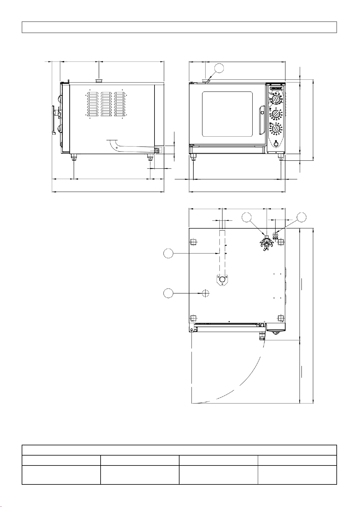
A- Electrical connection
B- Water inlet Ø 3/4”
C- Water drainage Ø 40 mm
D- Cooking chamber relief valve
5 x 1/1 GN
1.2A Dimensions mod. 5 x 1/1 GN
Dimensions
Capacity
Trays distance
Empty weight
mm 709 x 827 x h 598
5 x 1/1 GN
10 x 1/2 GN
67 mm
70 kg
O 40
B
73
A C D
60,4 467
,
1
827,4 48,7 528,6 20,5 1294,5 597,8
Page 5
5 - 10 - 15 x 1/1 GN ANALOGIC
5
D
D
70,8
48,7
59,5 286,5
481
121
589
161,9
563,2
101,9
31,9 646,2
31,1
827
709,2
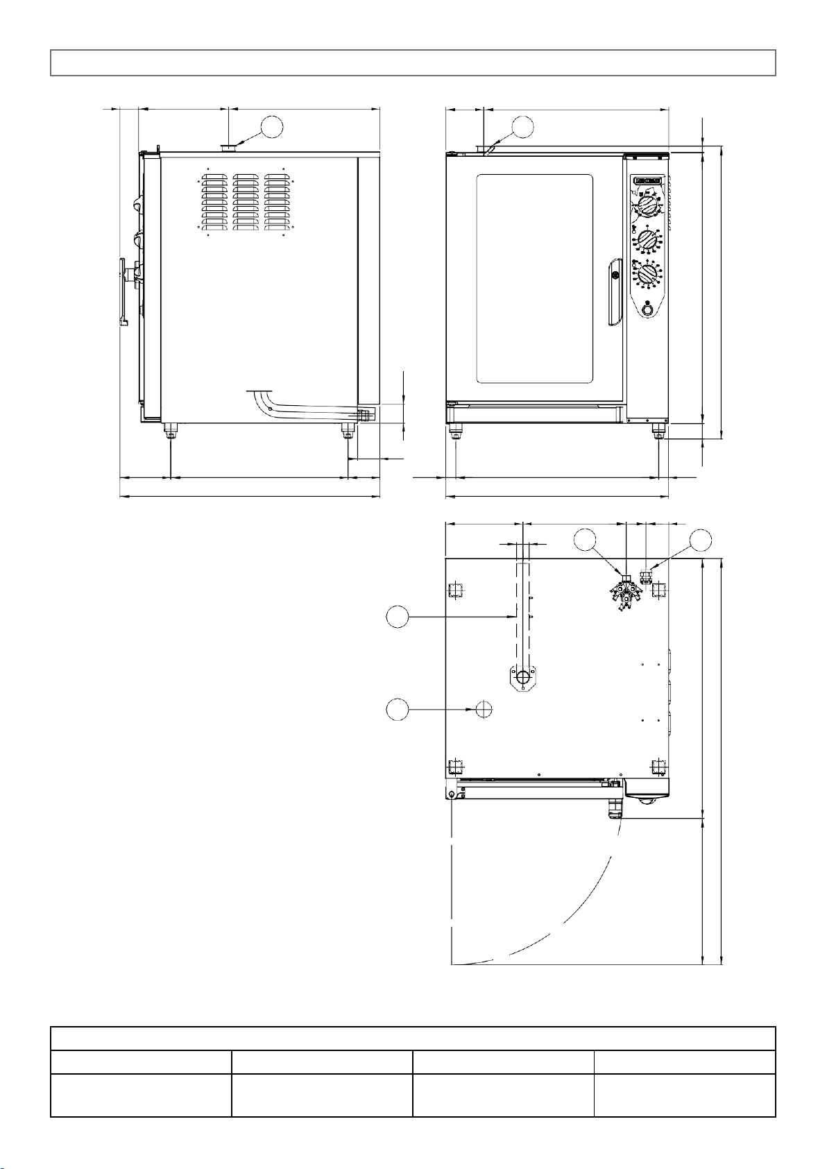
A- Electrical connection
B- Water inlet Ø 3/4”
C- Water drainage Ø 40 mm
D- Cooking chamber relief valve
10 x 1/1 GN
1.2B Dimensions mod. 10 x 1/1 GN
Dimensions
Capacity
Trays distance
Empty weight
mm 709 x 827 x h 932
10 x 1/1 GN
20 x 1/2 GN
67 mm
90 kg
246 O 40
328
B
63 73
A
C
D
60,4 467
,
1
827,4
863,6
932,8 20,5 1294,5
Page 6
5 - 10 - 15 x 1/1 GN ANALOGIC
6
59,5 298,5
489
121
629
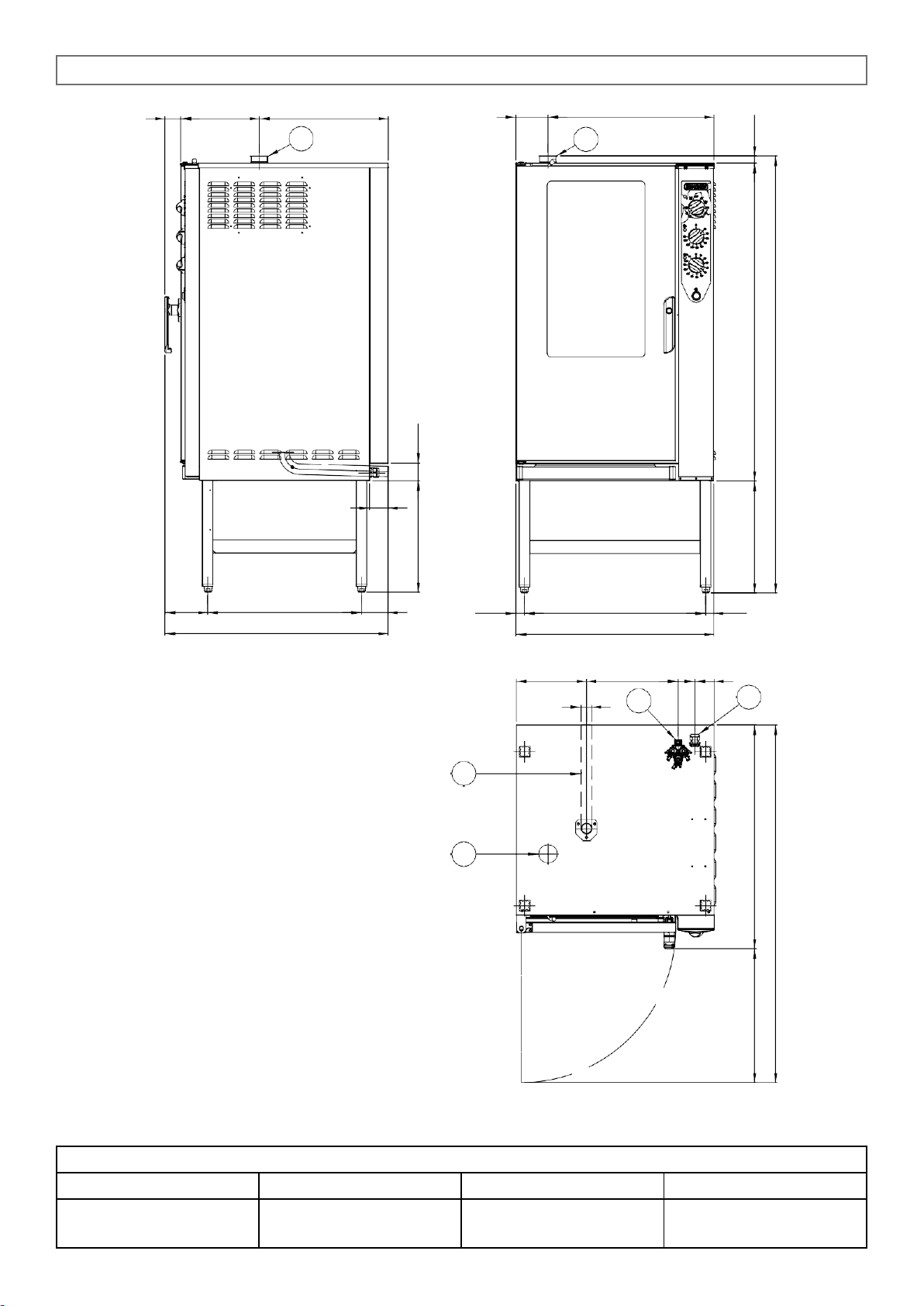
A- Electrical connection
B- Water inlet Ø 3/4”
C- Water drainage Ø 40 mm
D- Cooking chamber relief valve
15 x 1/1 GN
1.2C Dimensions mod. 15 x 1/1 GN
Dimensions
Capacity
Trays distance
Empty weight
mm 749 x 846 x h 1655
15 x 1/1 GN
30 x 1/2 GN
67 mm
160 kg
D
31,9
686,2
749,2
31,1 266 O 40
348
B
63 73
A C D
D
70 161,9
583,2
846,2
101,1
422,7 65,8 507
,
5
847 423,7 1203,6 27,2 1354,5 1654,5
Page 7
5 - 10 - 15 x 1/1 GN ANALOGIC
7
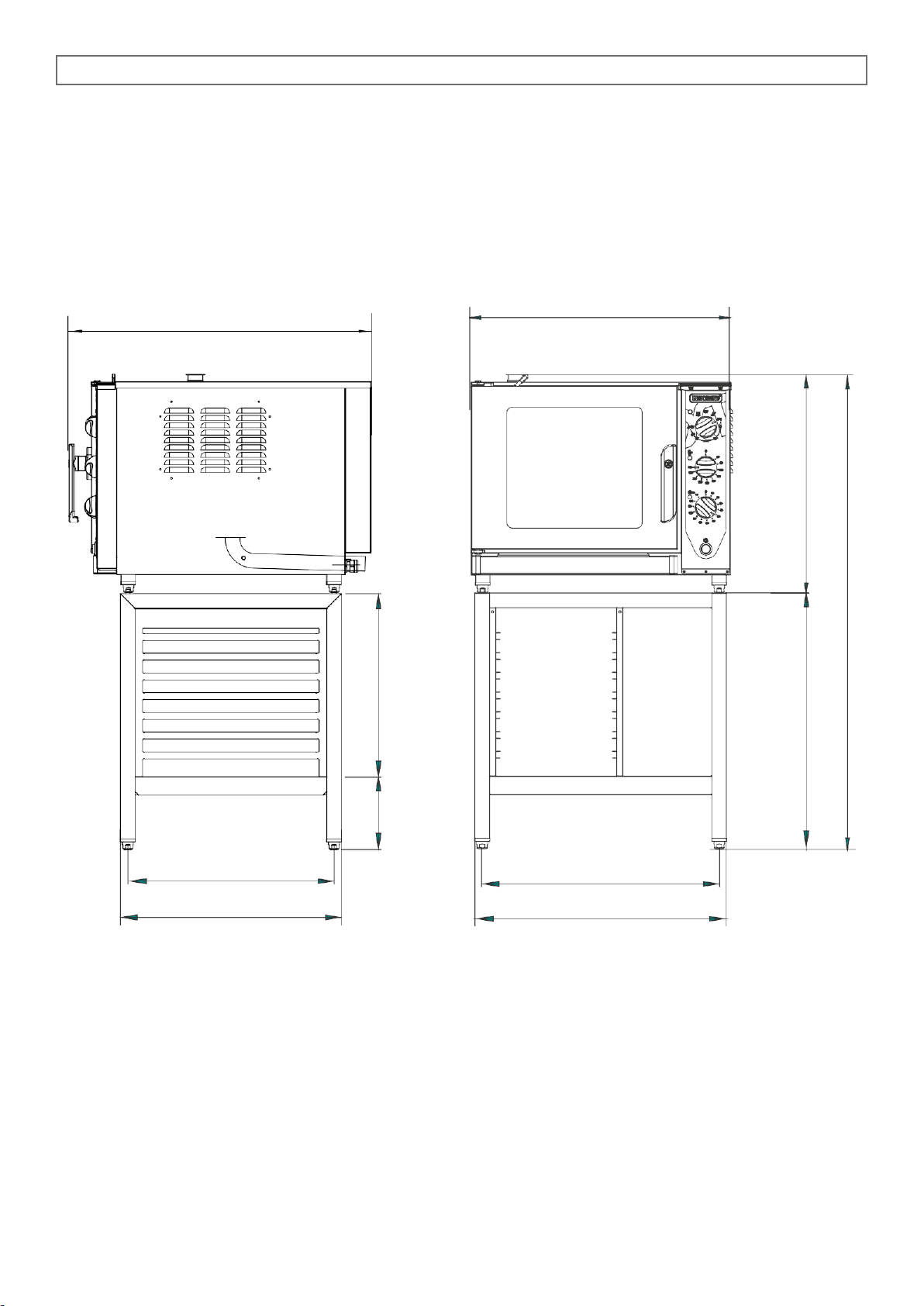
5 x 1/1 GN + SG-51R
709,2
7 x 1/1GN
646
686
827
563
603
198
500
700
597,8
1297,8
Page 8
5 - 10 - 15 x 1/1 GN ANALOGIC
8
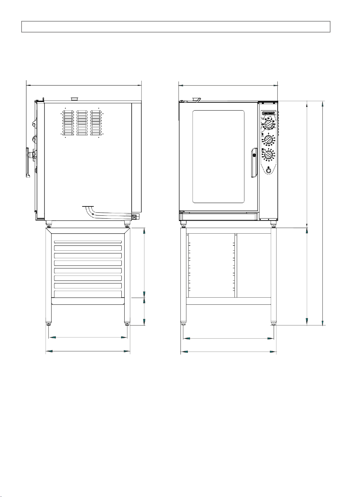
10 x 1/1 GN + SG-51R
709,2
7 x 1/1GN
646
686
827
563
603
198
500
700
932,8
1632,8
Page 9

5 - 10 - 15 x 1/1 GN ANALOGIC
9
1.3 TRANSPORT OF THE OVEN AND PACKAGING REMOVAL
Upon receipt of the oven and before installing it, check the packaging is intact and there are not visible
damages. Also check that along with the oven you receive also the documentation, consisting of:
• Instructions for installation, use and maintenance
• Chart to check correct installation
• Wiring diagram
• Label ISO 3864-1
Before bringing the oven to the point, where it must be installed, check the following:
• The doors are large enough to allow passage of the oven
• The floor supports the weight.
According to the model of oven, its dimensions and its weight, use suitable facilities to handle goods during transport and installation, able to guarantee stability in order to avoid overturning, falls or uncontrolled
movements of the appliance or its components.
Keep the oven packed until you reach the site where the oven is going to be installed.
The packaging makes the handling of goods easier and protects the oven from accidental push.
During moving and installation of the oven, the installer must comply with accident-prevention regulations
in force at the place of installation (use of safety shoes, gloves, etc.)
Remove the packaging taking care not to damage the oven.
The adhesive film, that protects the surfaces made of stainless steel can be removed also after you have
positioned the oven on the corresponding stand or the support surface.
ATTENTION: Packaging materials and adhesive film are potentially dangerous.
For this reason, they must be kept out of the reach of children and properly disposed
of in compliance with local directives.
You should separate packaging materials (wood, cardboard, plastic...) and dispose of
them separately, in compliance with directives in force at installation site.
Note: Take the protective film off the stainless steel parts by hand before starting the appliance.
Do not use abrasive substances and/or metal objects.
Clear any adhesive residues using a sponge soaked in solvent.
If the oven is heated up before removing the adhesive film, the removal of the film and cleaning of residues
of glue will be much more difficult.
Page 10
5 - 10 - 15 x 1/1 GN ANALOGIC
10
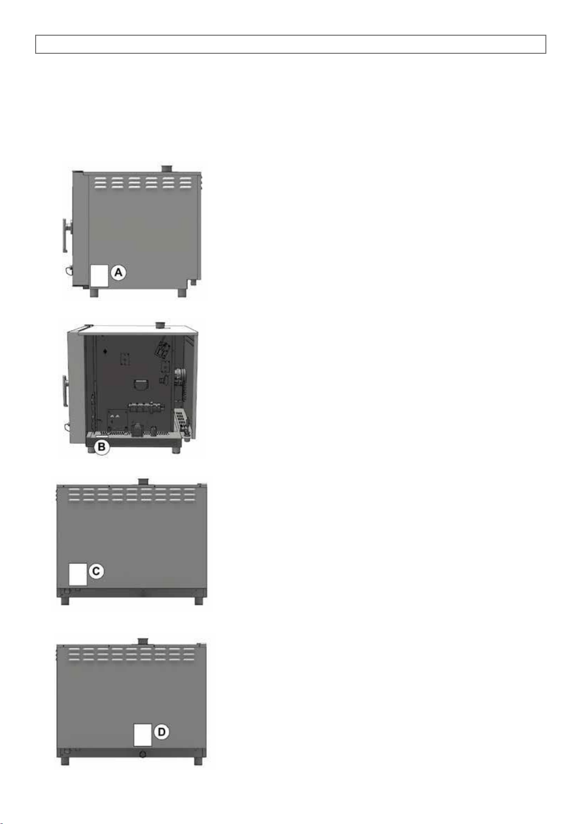
1.4 INFORMATIVE LABELS
On each oven there are applied some metal labels, that give important info concerning characteristics of
the oven, electric and plumbing connections and eventually the drain connection.
On the right hand side panel there is the label A.
The info contained on this label are:
• Name and address of the manufacturer
• Oven model
• IPX protection grade against water jet.
• Conformity to EC directives.
• Power input and power supply (single or three phase).
• Serial number of the oven
• Symbol of European Directive 2012/19/UE
Removing the right hand side panel, on the oven chassis you find
label B.
On this label the serial number of the oven is repeated.
In this way, the customer or the installer can find the serial number of the oven also when the label A is dirty or damaged.
In the back of the oven, near the connector for water connection
there is the label C.
Label C indicates water features necessary for a correct functioning of the oven.
Same features are listed at paragraph 2.3A of this manual.
Close to the drain there is the label D, containing info concerning
drain connection.
Page 11
5 - 10 - 15 x 1/1 GN ANALOGIC
11
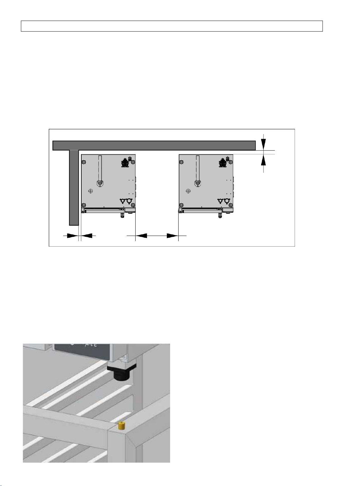
*
> 50 cm
> 1 cm
*
1.5 POSITIONING OF THE OVEN
The place where the oven will be installed must comply the following requirements:
• Be protected from atmospheric agents and have an adequate air circulation;
• Comply with regulations concerning safety at work;
• Have a room temperature between 5 °C and 35 °C with a humidification not higher than 70%.
Place the oven and proceed with levelling using adjustable feet.
Keep a suitable distance at the back, in order the label of equipotential clamp is easy to see when the
oven has been installed. The same clamp must be easy to access to install equipotential cable after the
oven has been installed in compliance with our instructions.
Install the appliance in a position that allows access to the right side for installation, maintenance and
technical assistance.
Maintain the minimum distances between the oven walls, (rear and right side) and either the brick walls or
the other appliances.
Take the protective film off the stainless steel parts
by hand before starting the appliance.
Do not use abrasive substances and/or metal objects.
If the oven is placed on its supports, supplied by us
on request, make sure the centre hole of the feet
snap on to the support pin which will guarantee
stability.
Page 12
5 - 10 - 15 x 1/1 GN ANALOGIC
12
CONVECTION + HUMIDIFICATON
COMBI DIRECT
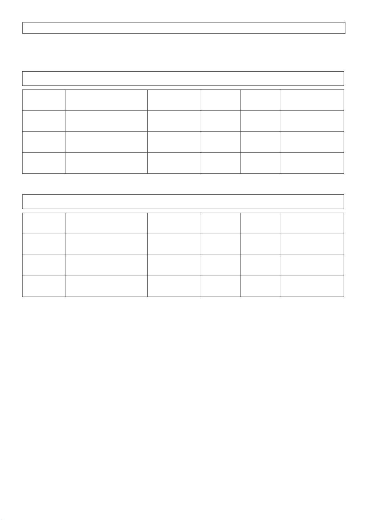
1.6 TECHNICAL DATA FOR ELECTRICAL CONNECTION
Model
Power loading
and voltage
no. and motor
power
Heating
power
Absorbed
current
Feed cable
section
5 x 1/1 GN
5 kW
380 - 415 V +3N~ 50 Hz
1 x 250 W
4.8 kW
8.5 A
5 x 2.5 mm
2
10 x 1/1 GN
10 kW
380 - 415 V +3N~ 50 Hz
2 x 250 W
9.6 kW
18.0 A
5 x 4.0 mm
2
15 x 1/1 GN
15 kW
380 - 415 V +3N~ 50 Hz
3 x 250 W
14.4 kW
25.0 A
5 x 6.0 mm
2
Model
Power loading
and voltage
no. and motor
power
Heating
power
Absorbed
current
Feed cable
section
5 x 1/1 GN
6 kW
230 V~ 50 Hz
1 x 250 W
5.8 kW
27.0 A
3 x 4.0 mm
2
10 x 1/1 GN
12 kW
380 - 415 V +3N~ 50 Hz
2 x 250 W
11.6 kW
20.0 A
5 x 4.0 mm
2
15 x 1/1 GN
18 kW
380 - 415 V +3N~ 50 Hz
3 x 250 W
17.4 kW
28.0 A
5 x 6.0 mm
2
Page 13
5 - 10 - 15 x 1/1 GN ANALOGIC
13
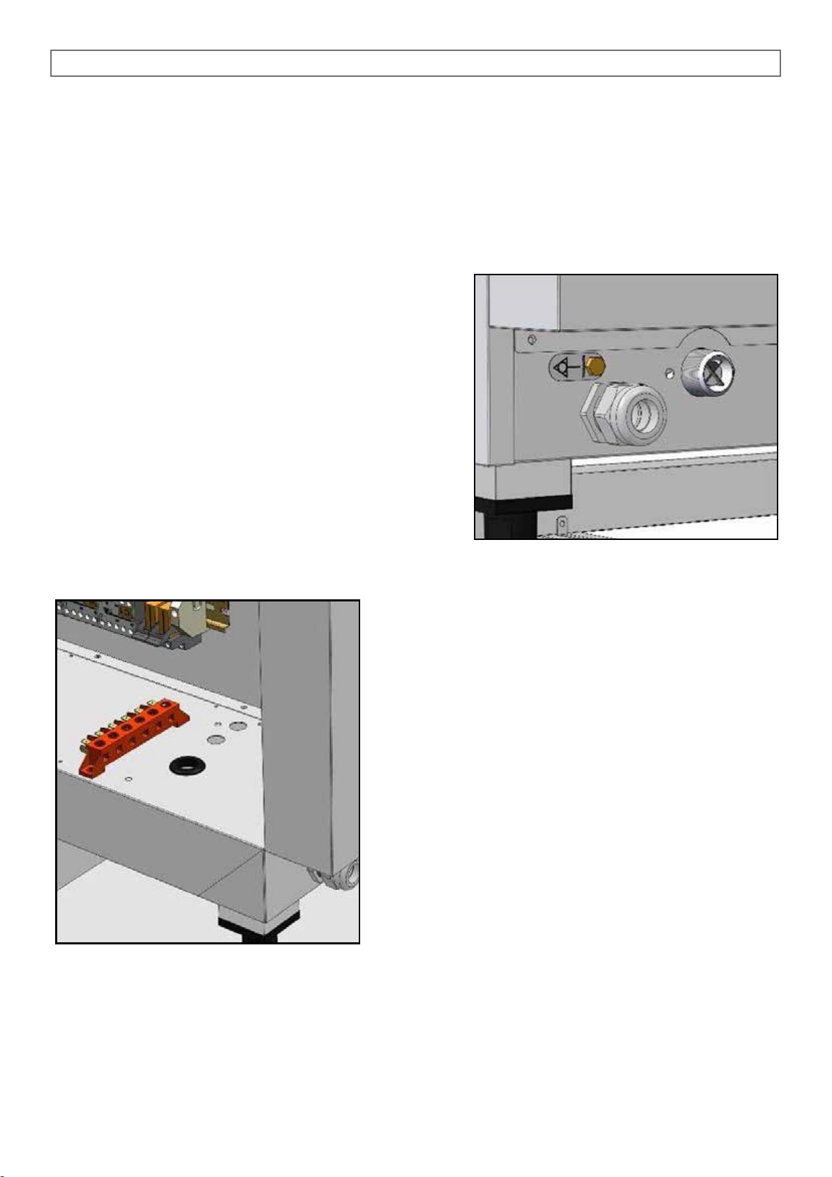
1.7 ELECTRICAL CONNECTION
When the appliance is delivered it is set to work at the voltage given on the rating plate affixed on the right
side of the appliance.
The terminal board used for connecting can be accessed from the right of the appliance, removing the
side panel.
The effectiveness of the equipotential system of which the
appliance is part of, must conform to current standards.
Connect using the screw you find near the power cable’s
relief cable strain, marked with the word EQUIPOTENTIAL.
The Manufacturer declines all and every responsibility if this
important accident prevention norm is not complied with.
If the feeding cable is damaged, it must be replaced by the
technical service or in any case by similar qualified personnel, in order to avoid any risk.
Before connecting the cable, remove the steel protection fixed to the ovens base with its specific screws, insert
the cable in the clamp-connector and then in the terminal
board zone, passing through the hole with the gasket near
the terminal board.
Once the electric connection has been carried out, reassemble the steel protection previously removed.
The specifications of the flexible cable for the electrical
connection should be no lower than those of the type with
rubber insulation H07 RN-F, with the cross section of the
wires as given in the technical data.
Install upstream a device that can ensure disconnection
from the main, with an opening distance of the contacts,
able to guarantee complete disconnection of the category
overvoltage III, in compliance with installation rules.
It is essential to connect the appliance to an effective earthing system; for this purpose the relative terminal with the symbol to which the earth wire is to be connected is on the terminal board.
Page 14
5 - 10 - 15 x 1/1 GN ANALOGIC
14
2.3 WATER FEATURES
The water must be suitable to human use with the following characteristics:
Temperature: included between 15 – 20°C
Total hardness: included between 4 and 12 °f (French degrees), it is advisable to install a softener up-
stream from the appliance that will maintain the hardness level at the mentioned values.
The oven’s running with water that has a higher hardness level will not be long before scale forms
on the walls of the oven and in this case the technical assistance required to repair such damage
is not covered by the guarantee.
Pressure: included between 150 and 250 KPa (1,5 – 2,5 bar).
Attention: higher water pressure values result in increased water consumption and can compromise the
correct functioning of some components.
Maximum chloride concentration (Cl-): less than 150 mg/litre.
Chlorine concentration (Cl2): less than 0.2 mg/litre.
pH: more than 7.
Water conductivity: included between 50 and 2000 µS/cm.
Attention: Water treatment systems that bring to different values to the ones above mentioned automati-
cally invalidate the guarantee.
The use of dosing systems designed to prevent the build-up of lime-scale in pipes (i.e. polyphosphate
dosing systems) is also prohibited since it may impair the performance of the appliance.
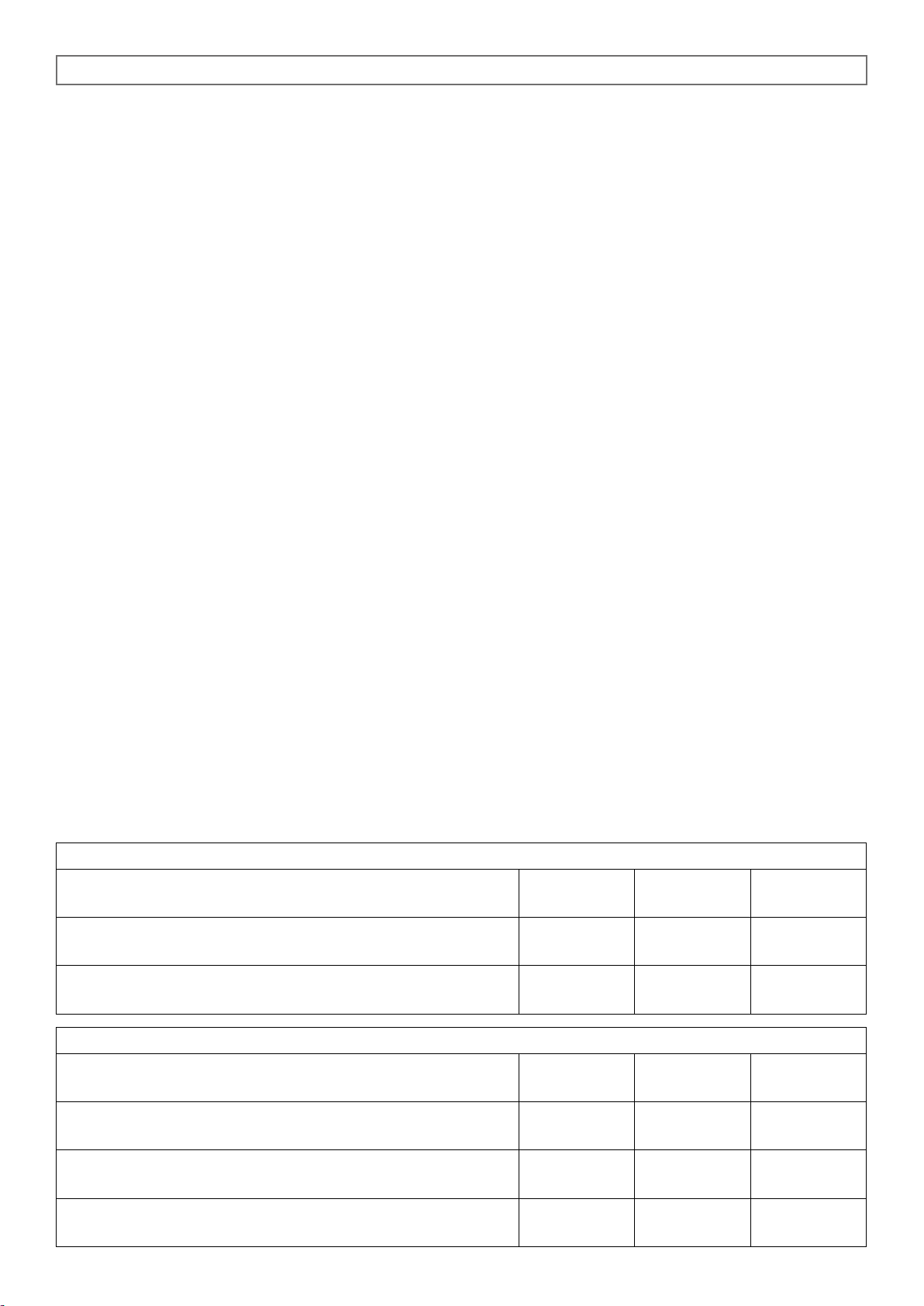
2.4 TECNICAL DATA TABLE FOR THE WATER SYSTEM
Convection + Humidification
105
5 x 1/1 GN
110
10 x 1/1 GN
115
15 x 1/1 GN
Condensation flow rate regulator - Fig. 3.0G
Optional
Ø 0.7 mm
Ø 0.7 mm
Ø 0.7 mm
Combined cycle water flow rate regulator Fig. 2.5A
Ø 0.4 mm
Ø 0.4 mm
2 x Ø 0.4 mm
Combi direct
105
5 x 1/1 GN
110
10 x 1/1 GN
115
15 x 1/1 GN
Condensation flow rate regulator Fig. 3.0G
Ø 0.7 mm
Ø 0.7 mm
Ø 0.7 mm
Steam water flow rate regulator Fig. 2.5B
Ø 0.5 mm
2 x Ø 0.5 mm
2 x Ø 0.55 mm
Combined cycle water flow rate regulato Fig. 2.5B
Ø 0.4 mm
Ø 0.4 mm
2 x Ø 0.4 mm
Page 15
5 - 10 - 15 x 1/1 GN ANALOGIC
15
2.5 HYDRAULIC CONNECTION – WATER INLET
The ovens have a water inlet coupling at the back. Always install an on-off valve between the appliance
and the water mains, making sure it is easy to operate.
We also suggest installing a cartridge filter on the water inlet pipe.
Always use a set of new water joints, eventual old joints must not be used again.
Plumbing connection must be always effected with cold water and rigid pipes.
Never use hoses to connect the oven to the water main.
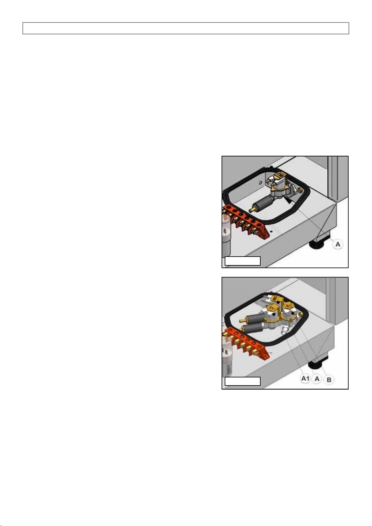
In Convection + Humidification models, the solenoid valve (B)
supplies the steam generation in Combination cycle (Fig. 2.5A).
In Combi Direct models, the solenoid valve (A) supplies the
steam generation in Steam cycle, the solenoid valve (A1) in
Combination cycle and the solenoid (B) supplies the steam
condensation system that comes out of the drainpipe (Fig.
2.5B).
Fig. 2.5A
Fig. 2.5B
Page 16
5 - 10 - 15 x 1/1 GN ANALOGIC
16
> 2°
0 ÷ 30 cm
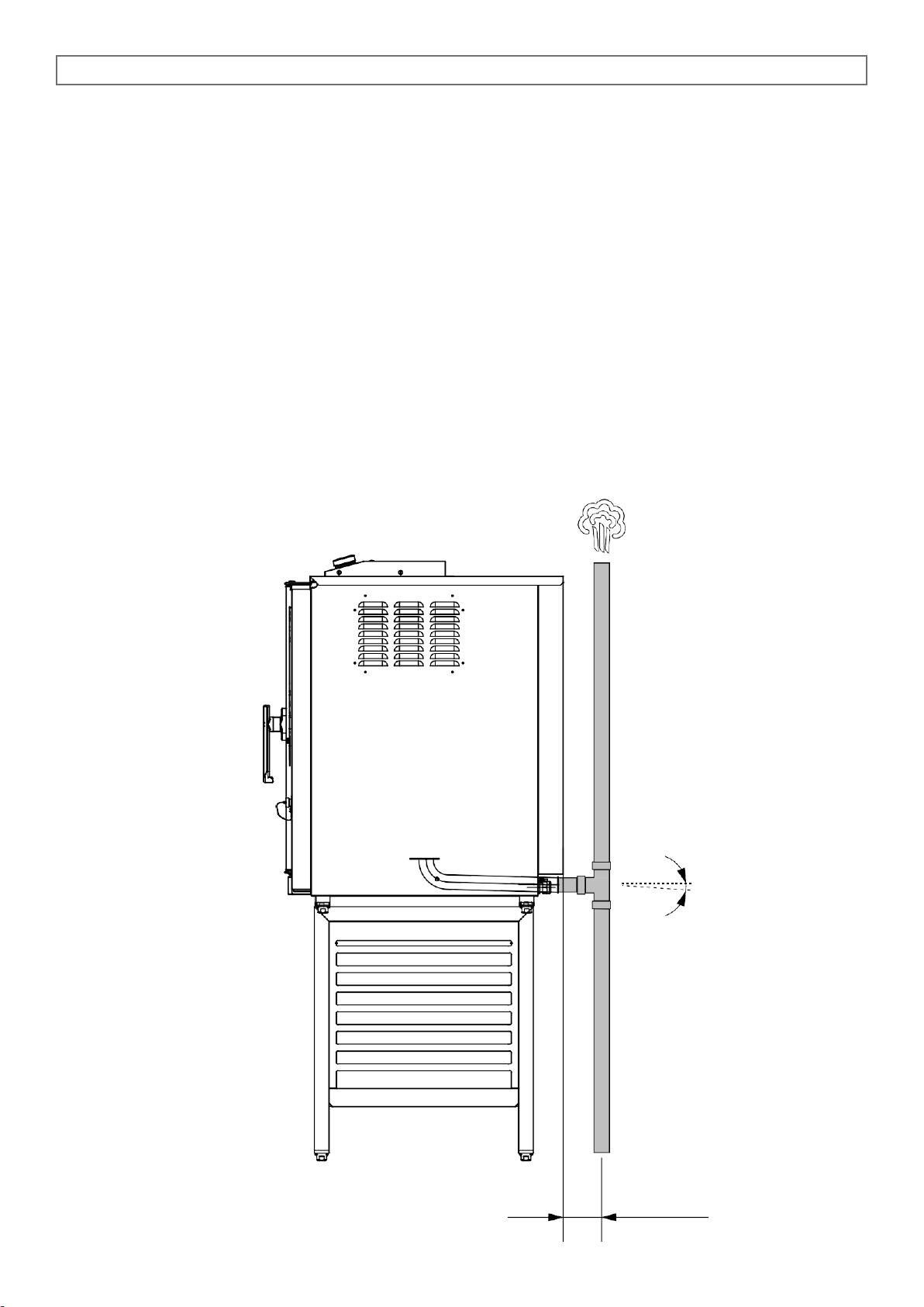
2.6 PLUMBING – WATER DRAINAGE
Drainage for the water is at the back of the oven and must be connected directly to the end of the stainless steel drainpipe.
The drain must have no trap and be made in rigid pipes that can withstand a temperature of 110°C.
Under no circumstances must pipe diameter be reduced. The actual pipe should be at atmospheric pressure with the appropriate funnel type air intake.
If the drainpipe is clogged for any reason steam can escape from the door and bad smells can be created
inside in the oven.
Page 17
5 - 10 - 15 x 1/1 GN ANALOGIC
17
3.0 CONTROL AND SAFETY DEVICES
The ovens are equipped with a set of control and safety devices for the electric and hydraulic circuits.
3.0A 2A fuse: it is in the auxiliary circuit to protect against short circuiting of the electrical system and is
inside its own support on the contactor’s fixing bracket.
3.0D Motor overload protection: a thermal probe disengages the motor when, for various reasons,
there is an overload. When the overload protection triggers it stops the motor and also disconnects the
heating elements or the gas valve. The probe is reset automatically when motor temperature drops.
3.0E Oven safety thermostat: disconnects the heating element or the gas valve when anomalies
related to overheating occur. Reset will have to be done manually when causes for thermostat operation
have been determined.
3.0F Door micro switch: it stops the oven working when the door is opened.
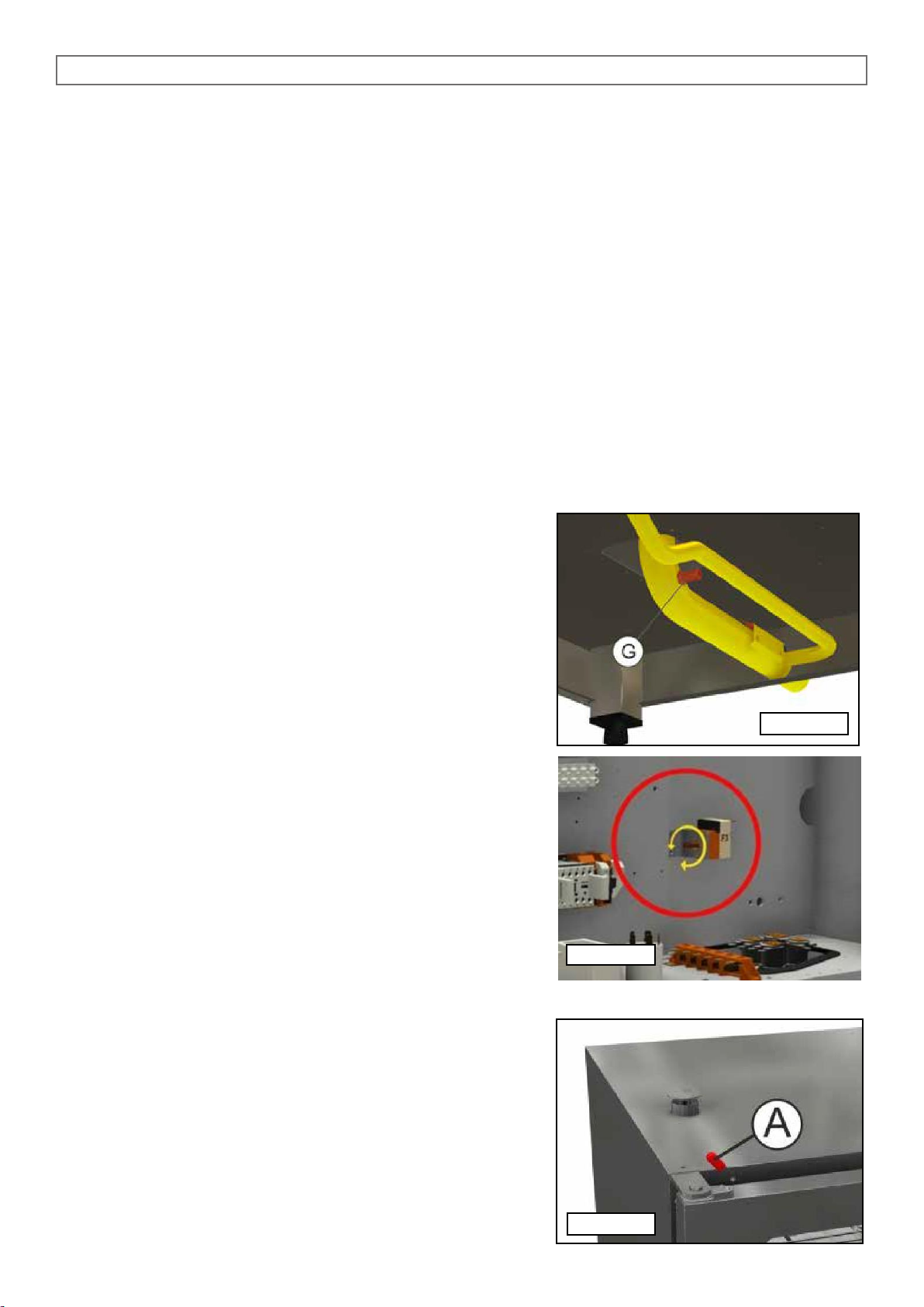
3.0G Thermostat system for condensation of discharge
steam: (optional in convection + humidification models): it com-
prises a solenoid valve controlled by a thermostat whose sensor
is housed in contact with the discharge.
The solenoid valve, via the injector (G), lets cold water into the
drainpipe to condense the steam when a temperature of 90°C is
reached (Fig. 3.0G).
Removing the side panel of the oven and acting on the F3 ad-
juster of the Pic.3.0G1, it’s possible to modify the condensation
system in the following way: if you turn the thermostat pin F3
counterclockwise until you hear a click, the function is disabled.
If you turn the pin counterclockwise without reaching the limit
stop, steam condensation system activates when the temperature in the drain pipe is around 30° C.
If you turn the pin counterclockwise till limit stop, condensation system activates when the temperature inside the drain is
around 90°C.
In our factory the ovens are supplied with F3 thermostat regulated at 90°C.
3.0 H Oven relief valve: its job is to adjust humidity inside the
cooking chamber.
The valve is manually activated acting on the knob (A)
(Fig.3.0H) on top of the door.
Fig. 3.0G
Fig. 3.0G1
Fig. 3.0H
Page 18
5 - 10 - 15 x 1/1 GN ANALOGIC
18
3.1 REPLACING SPARE PARTS
The replacement of damaged parts must be done only by qualified personnel.
To request the manufacturer parts to be replaced must be provided the oven model and serial number.
These data can be found on the rating plate attached to the oven (see par. 1.4).
Before starting to replace spare parts make sure, for safety reasons, that the electricity main switch is off
and that the water on-off valve are closed.
3.2 CHECKING THE FUNCTIONS
After completing the installation of the oven is necessary to perform a leak test to the water network.
The installer must check with suitable measurement instruments that the air noise emissions have
a level of sound pressure type weighed A, less than 70 dB (A).
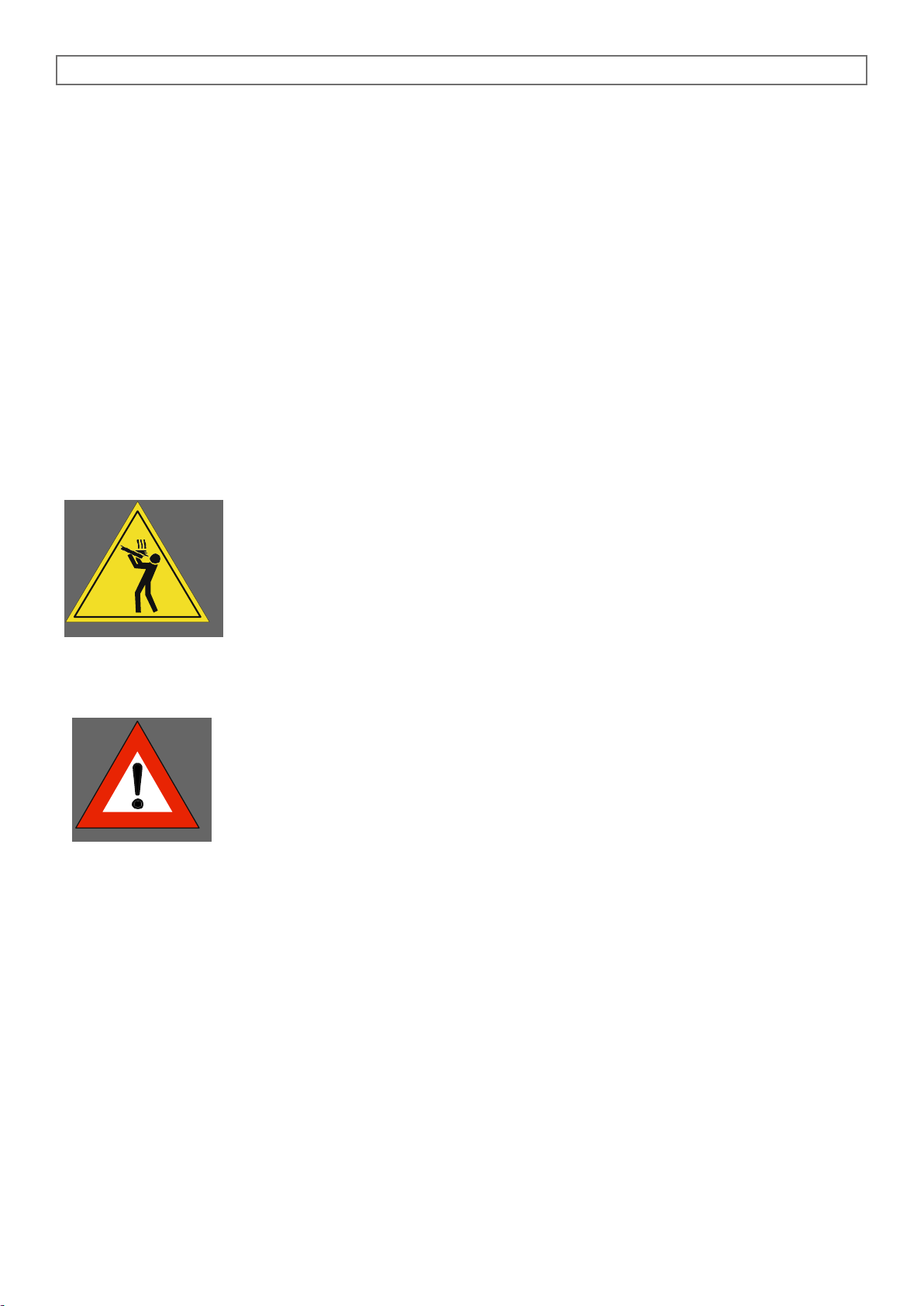
The label ISO 3864-1 here on the side must be stuck on a visible surface, 1,6 mt
height from the ground.
On floor models, the label is already stuck in the suitable position.
On table models, the label is supplied along with the documentation and must be
stuck after installation on a visible part of the appliance at 1.60 mt from the ground.
The installer must verify proper operation of the oven, providing the necessary instructions to the customer
and give this instruction manual that the user must follow carefully.
IMPORTANT:
Before the operator turns the oven on and uses it for any cooking or washing cycle,
it is necessary that the installer or a qualified technician checks all the connections
have been done up to the instructions stated in our manual.
The technician or the installer must therefore check as follows:
• The oven must stand (horizontal position) and be fixed on a stand or a shelf, that can guarantee stability.
• Wiring connection must be effected according to the directives and the feed cable section must be no
lower than the one indicated in the manual.
• Pressure and hardness of the water must comply the values indicated in this manual;
• If the oven is supplied with drain pipe, this must be connected properly and the materials used should
withstand the working temperature.
After you have checked everything, open the water on-off valve, eventually the gas on-off valve and the
protection switch, all installed upstream.
The installer must check the proper functioning of the oven and give to the operator necessary instructions
for a correct use of the oven, and also verify that the operator owns a copy of this manual.
At the end the installer must fill in and sign the chart for correct installation and give it to the customer, who will keep it for all warranty period of the oven.
Page 19
5 - 10 - 15 x 1/1 GN ANALOGIC
19
4.0 INSTRUCTIONS FOR A SAFE USE OF THE OVEN
• Ensure the oven is on a stable position and safety devices installed upstream are efficient.
• Always use adequate protection gloves to introduce or pull out the trays.
• Always pay maximum attention to the floor, that due to cooking steam could be slippery.
• In order to avoid burns, never use trays or containers with liquids or fluids over a level that can be easily
controlled at sight.
• Don’t put trays or other kitchen tools on the oven.
• Periodically have a check with technical service and replace eventual damaged parts, that could alter
the proper functioning of the oven or be a danger.
• Often clean the oven following the instructions stated in this manual.
4.1 MAX. FOOD LOADING
Oven model
Number of trays
Max. food loading
105
5 x 1/1 GN
13 kg
110
10 x 1/1 GN
25 kg
115
15 x 1/1 GN
40 kg
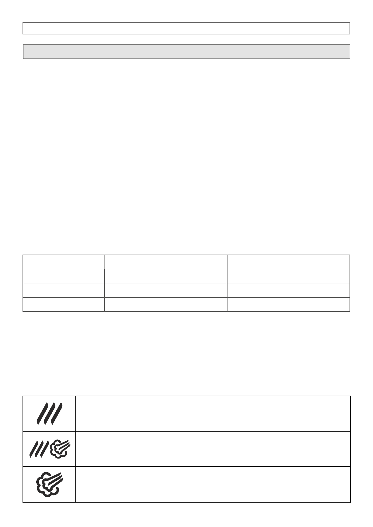
For a correct comprehension of the terminology used in the following paragraphs, we underline that cooking phase is the period of time in which the oven carries out one of the following cooking modes:
Convection hot forced air
(temperature range between 50 - 270°C)
Combination hot forced air and steam
(temperature range between 50 - 270°C)
Steam
(temperature range between 50 - 100°C)
USE AND MAINTENANCE
Page 20
5 - 10 - 15 x 1/1 GN ANALOGIC
20
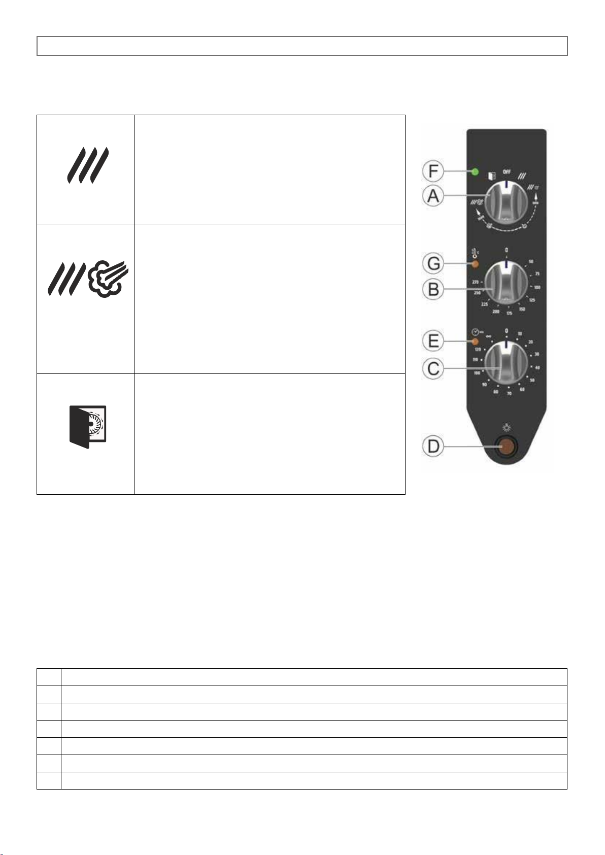
Convection forced hot air cycle
(temperature range between 50-270°C)
Turn the cycle selector knob (A) to the symbol shown
on the left and select the cooking temperature using
thermostat knob (B).
Combination cycle, hot air and steam
(temperature range between 50-270°C)
Turn the cycle selector knob (A) in the adjustment
zone among the symbols shown on the left (with humidity from a minimum to a maximum) and select the
cooking temperature using thermostat knob (B).
The selector knob (A) allows a progressive regulation for humitidy adjustment.
Cooling down cycle
Open the door and turn the cycle selector knob (A)
to the symbol shown on the left.
This cycle allows the motor fan to work with open
door, and to cool down quickly the cooking chamber.
4.1 PROGRAMMING AND OPERATION MOD. CONVECTION + HUMIDIFICATION
4.1 A COMPONENTS DESCRIPTION PANNEL CONVECTION + HUMIDIFICATION
A
Cycle selector knob
B
Cooking chamber thermostat
C
Timer
D
Chamber lighting ON/OFF button
E
Pilot light timer ON
F
Pilot light oven power supply ON
G
Pilot light cooking chamber heating ON
Page 21
5 - 10 - 15 x 1/1 GN ANALOGIC
21
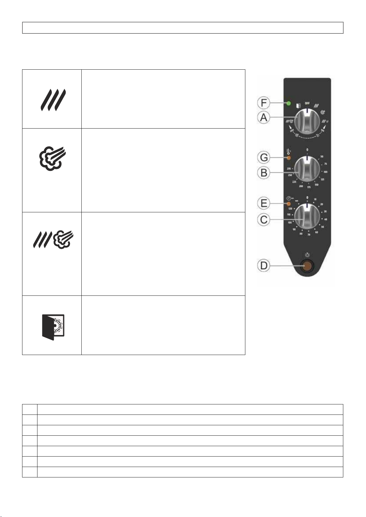
Convection forced hot air cycle
(temperature range between 50-270°C)
Turn the cycle selector knob (A) to the symbol shown
on the left and select the cooking temperature using
thermostat knob (B).
Steam cycle
(temperature range between 50-100°C)
Turn the cycle selector knob (A) to the symbol shown
on the left and select the cooking temperature using
the thermostat knob (B).
Important: the max. allowed temperature will be
100°C, even if the thermostat knob will be positioned
on higher values.
Combination cycle, hot air and steam
(temperature range between 50-270°C)
Turn the cycle selector knob (A) to one of the seven
adjustment positions among the symbols shown on
the left (with steam flow from a minimum to a maximum) and select the cooking temperature using
thermostat knob (B).
The selector knob (A) allows a progressive regulation for humitidy adjustment.
Cooling down cycle
Open the door and turn the cycle selector knob (A)
to the symbol shown on the left.
This cycle allows the motor fan to work with open
door, and to cool down quickly the cooking chamber.
4.2 PROGRAMMING AND OPERATION MOD. COMBI DIRECT
4.2A COMPONENTS DESCRIPTION PANNEL COMBI DIRECT
A
Cycle selector knob
B
Cooking chamber thermostat
C
Timer
D
Chamber lighting ON/OFF button
E
Pilot light timer ON
F
Pilot light oven power supply ON
G
Pilot light cooking chamber heating ON
Page 22
5 - 10 - 15 x 1/1 GN ANALOGIC
22
4.4 STARTING THE OVEN
Ensure that water supply are turned on and that the electricity supply is switched on.
Select the cooking time with the timer (C) that goes up to a maximum of 120 minutes; for longer cooking
times, select the (∞) nonstop position.
When the timer is on and the door is closed the cooking cycle starts together with the electric fan, heating
and steam generation, if selected.
When the set time is finished a buzzer signals that cooking is finished and all the functions stop.
When selecting the cooking time always remember the time needed to pre-heat the oven.
It ‘a good practice to observe this caution before introducing the food to be cooked in the oven.
4.5 AUXILIARY COMMANDS AND CONTROLS
4.5A Internal cooking chamber lighting
All “ANALOG” models are equipped with internal light bulb. Its activation is controlled by the button (D).
4.5B Cooking chamber preheating
It is always advisable to pre-heat the oven before cooking food.
The time needed to heat the oven should be set taking into account that in the hot air convection cycle it
takes about 10 minutes to reach 220°C.
Having selected the desired time and temperature, switch the oven on without food inside.
At the end of the set time the ring signals that cooking can start.
In the steam cycle it is always advisable to preheat the oven, turning the steam adjuster knob round to
MAX, for 10 minutes without opening the door.
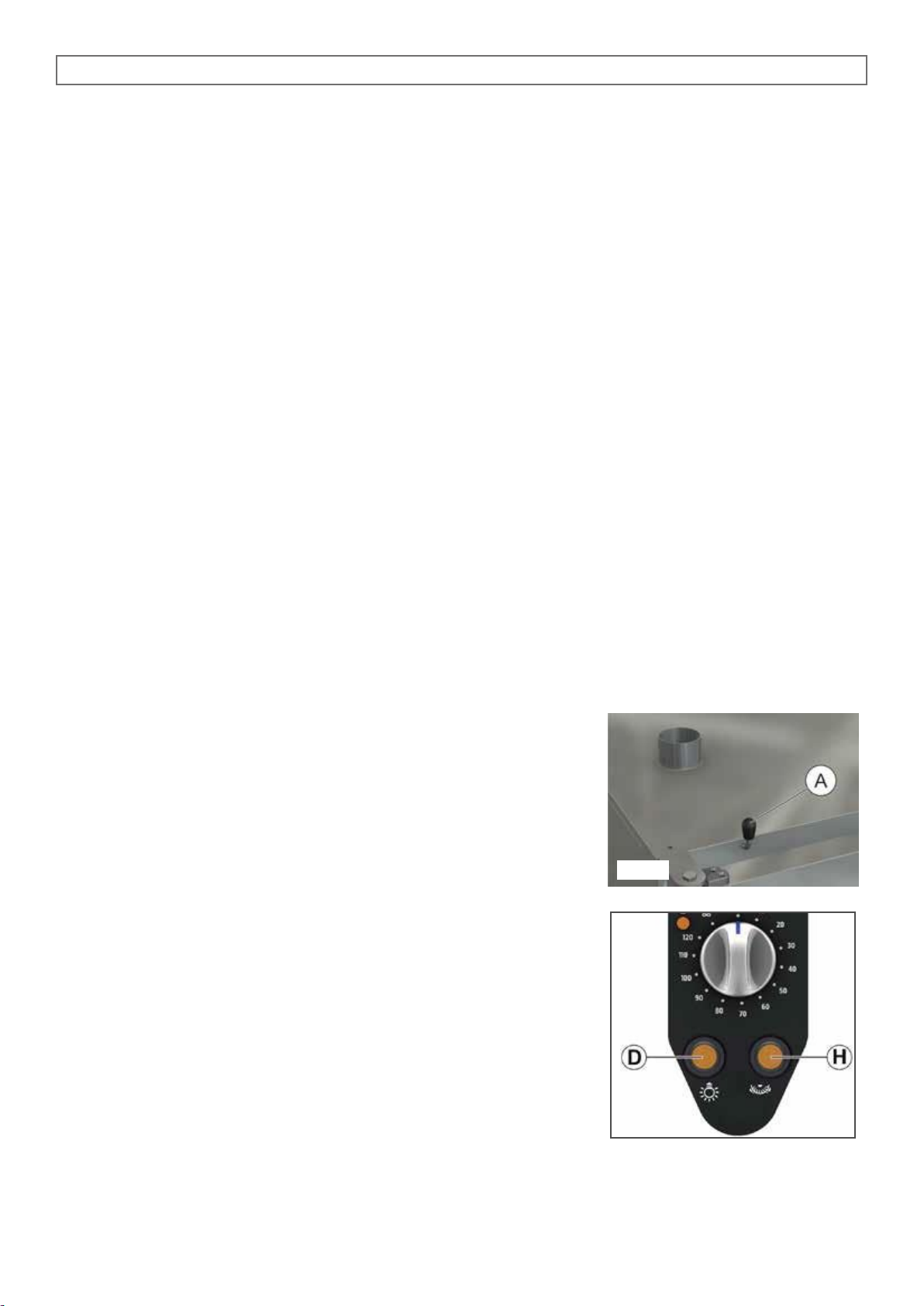
4.5C Release valve (Fig. 2)
All models are equipped with this system, which regulate the humidi-
ty inside the cooking chamber.
The steam relief valve is opened and closed by rotating knob (A).
4.5 D Autoreverse (OPTIONAL)
Autoreverse function is an optional.
When it is installed, its activation is controlled by the H switch, placed
on the lower part of the control panel.
By pressing H switch, Autoreverse function, that reverses the fan rota-
tion every 4 minutes to improve cooking uniformity, is activated.
Activation is confirmed by switch pilot light, which is on.
4.6 TURNING THE OVEN OFF
The oven is turned off by turning the cycle selector knob round to position 0.
Fig. 2
Page 23

5 - 10 - 15 x 1/1 GN ANALOGIC
23
9.0 MAINTENANCE
It is compulsory to turn the main switch off and close the water on-off valve, both installed upstream from
the oven before servicing it.
The oven should be cleaned at the end of each working day, using specific products only.
9.0A Cleaning of external oven parts
All external stainless steel parts should be:
1 - cleaned with clear, soapy water;
2 - rinsed with water;
3- dried thoroughly.
It is absolutely forbidden to use scrapers, metal soap pads and other common steel tools as they could
besides scratching the surface, deposit iron particles that, oxidizing would cause rust to form.
DO NOT WASH THE APPLIANCE WITH JETS OF WATER
DO NOT USE PRODUCTS TO WASH THE STAINLESS STEEL PARTS, WHICH CONTAIN CHLOR
(BLEACH, CHLORINE ACID) EVEN IF WATERED DOWN.
9.0 B Cooking chamber cleaning
The oven cooking chamber must be cleaned from residues of food and fat at the end of each cooking process.
Proceed as follows:
1. Heat the oven at a temperature of 80-90°C in steam mode to soften the dirty.
2. Vaporize the internal part of the cooking chamber with a specific detergent suitable for stainless steel.
3. Rinse with a lot of water using a sponge or a hand shower.
ANY RESIDUES OF DETERGENT COULD DAMAGE THE PARTS IN STAINLESS STEEL WHEN THE
COOKING CHAMBER WILL BE HEATED UP.
The fan must be kept clean to avoid grease and fat from depositing on the blades causing motor revolutions
to decrease leading to a reduction in the flow of air and dangerous mechanical stress to the motor itself.
9.1 WHAT TO DO IN CASE OF A BREAKDOWN AND/OR EXTENDED PERIOD OF NON USE
When the appliance is not used for long periods of time :
1.
Turn the main switch off
2.
Close the water on-off valve (both installed upstream from the oven);
3.
Leave the door open so air can circulate and prevent bad odors;
4.
With a cloth spread a thin protective layer of Vaseline oil on all stainless steel surfaces;
If the oven does not work properly, breaks down or if the safety thermostat triggers, switch the oven off,
disconnect the electricity and water supply and notify the technical assistance service.
All work of installation, maintenance and repairs should be carried out exclusively by qualified and
authorized personnel.
Page 24
5 - 10 - 15 x 1/1 GN ANALOGIC
24
10.0 COOKING TIPS
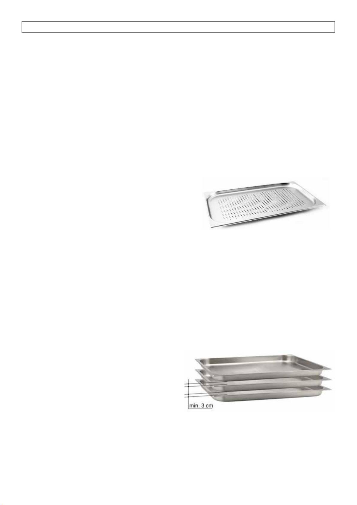
For best results we recommend the use of GASTRONORM trays , making sure to always leave a space
of at least 3 cm between foods of a baking tray and the tray above it, in order to allow the perfect air circulation. it is advisable to avoid the food to be cooked overflows from the pan , or in case this is not possible, avoid placing the pan on the top floor to that affected by the situation described .
Can be performed simultaneously cooking of different foods at the same temperature , avoiding the overlapping of flavors, the products stronger flavor will always placed in the top of the cooking chamber.
For the choice of the optimal cooking temperature must be taken into account the following rule: select a
lower temperature by about 20 % compared to the one set in traditional ovens without ventilation.
The forced ventilation system, of which this oven is equipped, ensure cooking in less time.
Failure to comply with the foregoing may affect the outcome of perfect cooking .
10.0A Convection cooking: the convection system, hot air and temperature between 50 and 270 °C, is
indicated for all types of cooking where want to get the food dry and crisp. To support this result it is advisable to open the release valve to help the output of steam from the cooking chamber.
10.0B Steam cooking: with this system, at variable temperature between 50-100 °C, can be performed cooking
very similar to the boiling in water.
Free steam pressure ensures even and delicate cooking,
and the loss of vitamins and minerals is almost nothing.
Cooking times are lower than those in water.
We always recommend using the perforated G.N. tray so that, when cooking is finished , there is no water
on the bottom of the tray. If you need to use the cooking liquid you can put an ordinary G.N. tray underneath.
10.0 C Steam-convection cooking: This method, commonly called “ combined”, combining variably the
two previous cooking methods.
Is indicated for all types of cooking where want to get food soft and juicy.
10.1 REMEDIES TO COOKING HITCHES
If cooking is uneven:
Check that there is at least 3 cm between the food cooking and the tray above it: if there is less space it will
not allow correct ventilation of the food to be cooked. Make sure that the foods to cook are not against each
other which would prevent correct ventilation between them.
Cooking temperature might be too high, try with a
lower temperature. If the food cannot stand direct
contact with the hot air it must be put in suitably deep
G.N. containers.
If the food is dry:
Reduce cooking time.
The temperature must be adequately lowered. Remember that the lower the temperature is the less weight
will be lost.
The combined cycle for a humidity rich cooking environment was not selected.
The food was not greased with oil or juices before it was put in to cook.
 Loading...