

Page 1
O
P
E
R
A
T
O
O
P
E
R
A
T
P
A
R
T
P
A
R
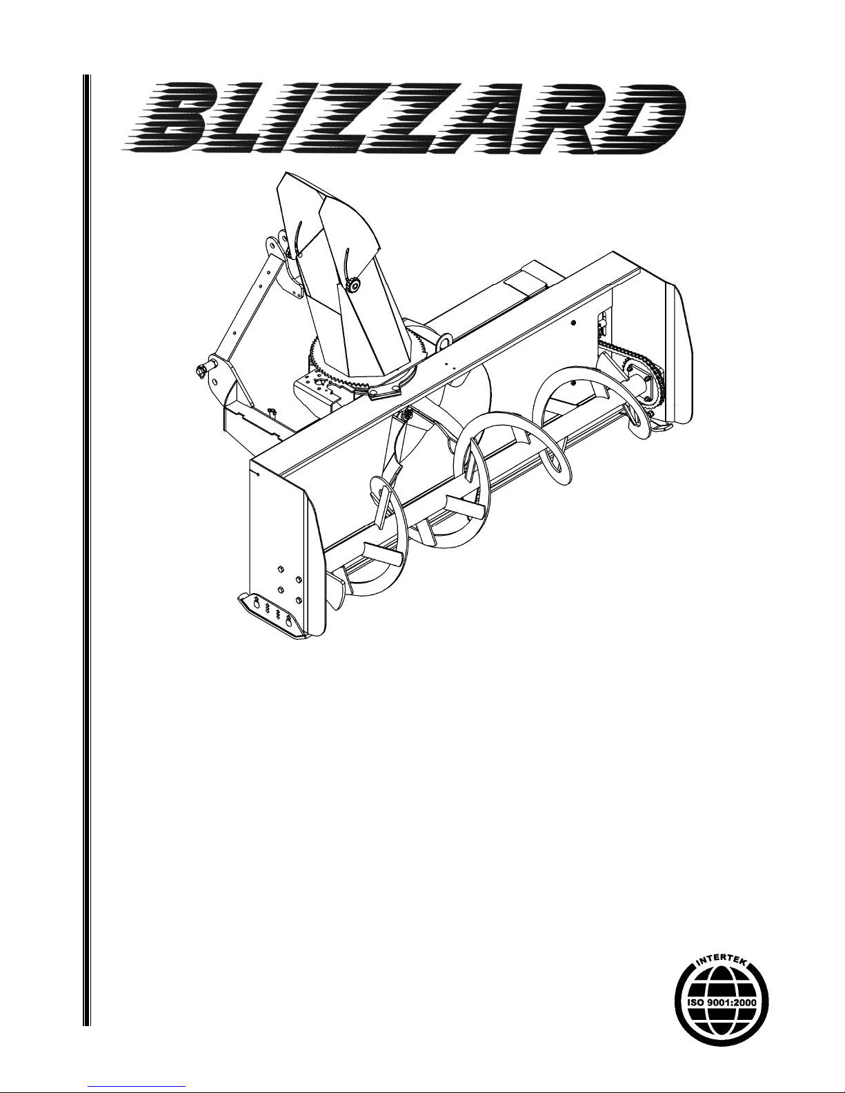
BLIZZARD B74C MODEL
S
T
S
SNOWBLOWER
SERIAL NO. 21502142 AND UP
O
M
M
R''
R
S
S
A
A
N
N
A
A
U
U
N
N
A
A
D
D
L
L
OM 0410SB-A
02/15
Page 2

Page 3

TABLE OF CONTENT
SPECIFICATIONS ........................................................................................................................................... 3
INTRODUCTION – TO THE PURCHASER ................................................................................................... 4
SAFETY PRECAUTIONS .......................................................................................................................... 5-11
Before Operation .................................................................................................................................... 5
Notice ...................................................................................................................................................... 6
The Snowblower .................................................................................................................................. 6-8
Before Operation..................................................................................................................... 6
Snowblower Operation ........................................................................................................... 7
Stay Clear of Rotating Drivelines ........................................................................................... 8
The Tractor ........................................................................................................................................ 9-10
General Information ................................................................................................................ 9
Operating the Tractor .............................................................................................................. 9
During Operation..................................................................................................................... 9
Roll-Over Protective Structure (ROPS) ................................................................................ 10
Transport............................................................................................................................................... 10
Maintenance ......................................................................................................................................... 11
Storage ............................................................................................................................................... 11
SAFETY DECALS ........................................................................................................................................ 12
ASSEMBLY ............................................................................................................................... ................ 13-31
Tractor Preparation .............................................................................................................................. 13
Snowblower Assembly ................................................................................................................... 13-31
Installation of Chute ............................................................................................................. 13
Installation of Snowblower with Three Point Hitch ............................................................. 14
Installation of Snowblower with Quick Hitch ....................................................................... 15
Installation of Manual Rotation Kit BER0077 ................................................................ 16-17
Installation of Hydraulic Rotation Kit BER0077 ............................................................. 18-20
Installation of Hydraulic Deflector Kit BER0079 ............................................................ 21-22
Installation of Electric Deflector Kit 8151 ....................................................................... 23-25
How to Determine Driveline Angles
............................................................................ 26
Determining Driveline Length ........................................................................................ 27-28
Driveline Installation ............................................................................................................ 29
Removing Snowblower from Tractor ............................................................................ 30-31
OM 0410SB-A 1
Angles at Each End of Driveline ......................................................................................... 27
Page 4

TABLE OF CONTENT
OPERATION ................................................................................................................................................ 32-33
General Preparation ................................................................................................................................ 32
Operating Controls ........................................................................................................... ....................... 32
Work and Travel Speed ......................................................................................................... 32
Raising and Lowering the Snowblower .................................................................................. 32
Adjustments ............................................................................................................................................. 32
Chain Tension Adjustment .................................................................................................... 32
Skid Shoe Adjustment ............................................................................................................ 32
Manual Deflector Adjustment ................................................................................................ 32
Snow Removal Methods ......................................................................................................................... 33
MAINTENANCE ............................................................................................................................................ 34-38
Maintenance ............................................................................................................................................. 34
Shearbolts ............................................................................................................................... 34
Drive shaft................................................................................................................................ 34
Driveline ................................................................................................................................... 34
Lubrication ................................................................................................................................................ 35
Driveline – Troubleshooting ................................................................................................................ 36-38
PARTS ......................................................................................................................................................... 39-48
Introduction ................................................................................................................................................... 39
Manual Holder ............................................................................................................................................... 39
Snowblower - B74C ................................................................................................................................. 40-42
Gearbox 663485 ........................................................................................................................................... 43
Driveline 4700159 ............................................................................................................. ............................ 44
BER0077 - Manual Rotation ......................................................................................................................... 45
BER0078 - Hydraulic Rotation ..................................................................................................................... 46
BER0079A - Hydraulic Deflector .................................................................................................................. 47
8151- Electric Deflector ................................................................................................................................ 48
TORQUE SPECIFICATION TABLE ................................................................................................... ............. 49
OM 0410SB-A 2
Page 5

SPECIFICATIONS
Features and Specifications B74C
Working Width 74"
Transport Width 74"
Working Height 26"
Length 47 3/4"
Single/Dual Auger Single
Auger Diameter 15"
Auger Flighting Thickness 5/16"
Impeller Diameter 24"
Impeller Width 9"
Impeller Shaft Diameter 1 3/8"
Number of Impeller blades 4
Roller Chain 60
Drive sprocket (# of teeth) 12
Driven sprocket (# of teeth) 32
Chain idler Manual adjustment
Gearbox Manufacturer Comer
Gearbox Description Model T-281A
Tractor RPM 540
Impeller RPM 540
Auger RPM 200
PTO Manufacturer Comer
PTO Description 40
Skid Shoe Adjustable
Skid Shoe Material High carbon steel
End Plate Thickness 3/16"
Back Plate Thickness 11ga
Impeller Housing Thickness 11ga
Impeller Blade Thickness 1/4"
Side Panel Bottom Thickness 3/16"
Cutting Edge Welded
Cutting Edge Dimension 3/8" x 2"
Chute Base Standard
Parking Stand Standard
Hitch Category Cat. 1 & 2
Quick Hitch Compatibility
HP Requirements - min-max (hp) 20-50
Operating Weight (lbs )-hy d. rot. & d efl. 715
Shipping Weight (lbs) 628
Approx. Set-up Time (min.) * 35
Chute Deflector Adjustment (standa rd) Manual
Hydraulic: cylinder (2"x5"), brackets, support, hoses & connectors
Chute Deflector Adjustment (option )
Chute Rotation
Chute
included.
Electric: actuator 5" - 75 lb brackets, hardware, switch & wires
included
Manual: worm gear w/ crank.
Hydraulic: 50cc hyd.motor, flow restric to r, ho ses & conn ec tors
included.
ASABE Compatible
Cat. 1 only
Two-part
* With manual rotation
OM 0410SB-A 3
Page 6

TO THE PURCHASER
INTRODUCTION
All BER-VAC and BLIZZARD products are
designed to give safe, depend able service if they
are operated and maintained according to
instructions. Read and understand this manual
before operation.
This manual has been prepared to assist the
owner and operators in the safe operation and
suitable maintenance of the implements. The
information was applicable to products at the time
of manufacture and does not i nclude modi fications
made afterwards.
Read and understand this operator's manual
before attempting to put an implement into service.
Familiarize yourself with the operating instruction s
and all the safety recommendations contained in
this manual and those labeled on the imple ments
and on the tractor. Follow the safety
recommendations and make sure that those with
whom you work follow them.
The Dealer is responsible for wa rran t y re gistra ti on of t he uni t y ou h ave pu rchas ed . T o assis t yo ur deal er i n
handling your needs, please record here after the mo del numb er and seri al number o f your imple ment and
tractor. It is also advisable to supply them to your insurance company. It will be helpful in the event that an
implement or tractor is lost or stolen.
Illustrations
The illustrations may not necessarily reproduce
the full detail and the exact shape of the parts or
depict the actual models, but are intended for
reference only
Direction Reference
Right Hand and Left Hand are determined by
those seen by the conductor standing b ehind the
equipment.
MODEL :
SERIAL NUMBER :
DATE OF PURCHASE :
OM 0410SB-A
4
Page 7

SAFETY PRECAUTIONS
SAFETY FIRST
This symbol, the industry's "Safety Alert Symbol", is used th roughout this manual and on labels
on the machine itself to warn of the possibility of personal injury. Read these instructions
carefully. It is essential that you read the instructions and safety regulations before yo u attempt
to assemble or use this unit.
DANGER : Indicates an imminently hazardous situation which, if not avoided, will
result in death or serious injury.
WARNING : Indicates a potentially hazardous situation which, if not avoided, could
result in death or serious injury.
CAUTION : Indicates a potentially hazardous situation which, if not avoided, may
result in minor or moderate injury.
IMPORTANT : Indicates that equipment or property damage could result if instructions
are not followed.
NOTE : Gives helpful information.
All products are designed to give saf e, dependable se rvice if they are o perated and maintained accord ing
to instructions. Read and understand this manual before operation
certain anyone operating this product reads this manual, and all other applicable manuals, to become
familiar with this equipment and all safet y precautions. Failure to do so could result in serious personal
injury or equipment damage. If you have any questions, consult your dealer.
. It is the owner's responsibility to be
BEFORE OPERATION
Children and Bystanders
Tragic accidents can occur if the opera tor is not
alert to the presence of children. Children are
generally attracted to machines and the work
being done. Never assume children will remain
where you last saw them.
1. Keep children out of the operating area and
under the watchful eye of another
responsible adult.
2. Be alert and turn machine off if children
enter the work area.
3. Before and when backing, look behind and
look for small children.
OM 0410SB-A
4. Never carry children while operating the
machine. They may fall off and be seriously
injured or interfere with safe operation of the
machine.
5. Never allow children to play on the machine
or attachment even when turned off.
6. Never allow children to operate the machine
even under adult supervision.
7. Use extra care when approaching blind
corners, shrubs, trees, or other obstructions
that might hide children from sight.
5
Page 8

SAFETY PRECAUTIONS - continued
NOTICE
A safe operator is the best insuranc e against accidents. All operators, no ma tter how experienced they
may be, should read this Operator's Manual and all other related manuals before attempting to operate an
implement. Please read the following sectio n and pay particular attention to all safet y recommendations
contained in this manual and those labeled on the implements and on the tractor.
THE SNOWBLOWER
Before Operation
1. Read and understand this operator's manual
and tractor operator's manual. Know how to
operate all controls and how to stop the unit
and disengage the controls quickly.
2. Never wear loose, torn, or bulky clothing
around the tractor and implement. It may
catch on moving parts or controls, leading to
the risk of accident.
3. Before the snow season, thoroughly inspect
the area where the equipment is to be used
and remove all doormats, sleds, boards and
other foreign objects.
4. Disengage clutch and shift into neutral
before starting the engine.
5. Do not operate equipment in wintertime
without wearing adequate winter garments.
6. Never attempt to make any adjustments
while engine is running. Read this manual
carefully to acquaint yourself with the
equipment as well as the tractor operator's
manual. Working with unfamiliar equipment
can lead to accidents. Be thoroughly familiar
with the controls and proper use of the
equipment. Know how to stop the unit and
disengage the controls quickly.
7. Keep all shields in place and properly tighten
all mounting hardware.
8. Periodically, inspect all moving parts for
wear and replace with authorized service
parts if an excessive amount of wear is
present.
9. Replace all missing, illegible, or damaged
safety and warning decals. See list of decals
in the operator's manual.
10. Do not modify or alter this equipment or any
of its components, or any equipment
function without first consulting your dealer.
11. Keep safety decals clean of dirt and grime.
12. Make sure the tractor is counterweighted as
recommended by your dealer. Weights
provide the necessary balance to improve
stability, traction and steering.
OM 0410SB-A
6
Page 9

SAFETY PRECAUTIONS- continued
Snowblower Operation
1. Before leaving the tractor/snowblower
unattended, take all possible precautions.
Park the tractor/snowblower on level ground,
place the transmission in neutral, set the
parking brake, disengage the PTO, lower the
snowblower to the ground, place all levers
including auxiliary control levers in neutral,
shut off the engine and remove the ignition
key.
2. Before starting the tractor/ snowblower,
remove the ice that might have accumulated
on the auger/fan, inspect and clean every
rotating part.
3. Prior to operation, clear work area of all
objects that can be picked up and thrown.
Mark all curbs, pipes, etc. that cannot be
moved.
4. Be sure the PTO switch/lever is in
OFF/disengaged position before starting
engine.
5. Exercise extreme caution when operating on
or crossing a gravel drive, walks, or roads.
Stay alert for hidden hazards or traffic.
6. Do not carry passengers.
7. Keep clear of all rotating parts. Do not put
hands or feet under, or into snowblower with
engine running. Be especially observant of
the snowblower areas of discharge, intake or
all other mechanical motions.
8. For your safety, do not work under any
hydraulically supported machine elements
that may creep down, suddenly drop or be
accidentally lowered.
9. Park the tractor/snowblower on level ground,
place the transmission in neutral, set the
parking brake, disengage the PTO, lower the
snowblower to the ground, place all control
levers in neutral, shut off the engine, remove
the ignition key and allow the rotating parts
to stop BEFORE unclogging the housing or
the chute and making any repairs,
adjustments or inspections. Use only a 36"
long stick of wood to unclog the snowblower.
10. If the snowblower starts to vibrate
abnormally, disengage the PTO, stop the
engine immediately and check for cause.
Excessive vibration is generally a sign of
trouble.
11. Do not run the engine indoors except when
starting engine and transporting attachment in or
out of building. Carbon monoxide gas is
colorless, odorless and deadly.
12. Do not attempt to operate on steep slopes. If
operating on slopes is necessary, exercise
extreme caution when changing direction.
13. Never operate snowblower without guards, and
other safety protective devices in place. All
tractor and snowblower shields and covers must
be correctly installed at all times. When
necessary to remove these, they must be
reinstalled immediately.
14. Never operate snowblower near glass
enclosures, automobiles, window wells,
embankments, etc., without proper adjustment
of snow discharge angle.
15. Never operate machine at high transport speeds
on a slippery surface.
16. Use extra caution when backing up.
17. Disengage power to auger/fan when
transporting or when not in use.
18. Never operate the snowblower without good
visibility and lighting.
19. Prolonged exposure to loud noise can cause
impairment or loss of hearing. Wear a suitable
hearing protective device such as earmuffs or
earplugs to protect against objectionable or
uncomfortable noises.
20. Never allow anyone near the work area.
21. Never allow anyone to operate the snowblower
until they have read the manual completely and
are thoroughly familiar with basic tractor and
snowblower operation.
22. Make sure the tractor is counterweighted as
recommended by your dealer. Weights provide
the necessary balance to improve stability,
traction and steering.
23. Always make sure all snowblower components
are properly installed and securely fastened
BEFORE operation.
24. Adjust housing height to clear gravel or crushed
rocks surface.
25. Keep away from chute discharge. This chute
has the capacity to throw debris at far distances.
26. Never direct chute discharge towards people or
animals. A thrown debris can cause serious
injury.
OM 0410SB-A
7
Page 10
SAFETY PRECAUTIONS- continued
Stay Clear of Rotating Drivelines
1. Entanglement in rotating driveline can cause
serious injury or death.
2. Keep tractor master shield and driveline
shields in place at all times. Make sure rotating
shields turn freely.
3. Wear close fitting clothing. Stop the engine and
be sure that PTO driveline is stopped before
making adjustments, connections, or cleaning
out PTO driven equipment.
4. Do not install any adapter device between the
tractor and the primary implement PTO drive
shaft that will allow a 1000 rpm tractor shaft to
power a 540 rpm implement at speeds higher
than 540 rpm.
5. Do not install any adapter device that results in
a portion of the rotating implement shaft,
tractor shaft, or the adapter to be unguarded.
The tractor master shield shall overlap the end
of the splined shaft and the added adaptor
device as outlined in the table.
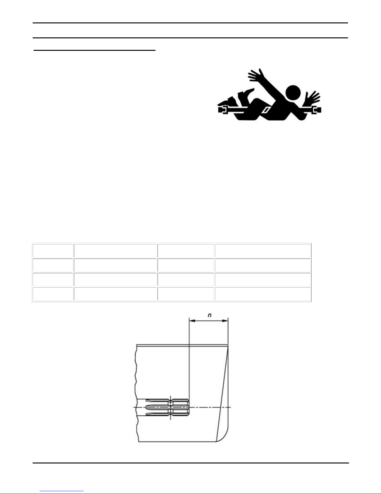
PTO Type Diameter Splines n ± 5 mm (0.20 in.)
1 35 mm (1.378 in.) 6 85 mm (3.35 in.)
2 35 mm (1.378 in.) 21 85 mm (3.35 in.)
3 45 mm (1.772 in.) 20 100 mm (4.00 in.)
OM 0410SB-A
8
Page 11

SAFETY PRECAUTIONS- continued
THE TRACTOR
General Information
1. Read the operator's manual carefully before
using tractor. Lack of operating knowledge
can lead to accidents.
2. Do not allow anyone but the operator to ride
on the tractor. There is no safe place for
extra riders
Operating the Tractor
1. Never run the tractor engine in a closed
building without adequate ventilation, as the
exhaust fumes are very dangerous.
2. Never allow an open flame near the fuel tank
or battery.
14. A minimum 20% of tractor and equipment
weight must be on the tractor front wheels
when attachments are in transport position.
Without this weight, tractor could tip over,
causing personal injury or death. The weight
may be attained with a loader, front wheel
weights, ballast in tires or front tractor weights.
Weigh the tractor and equipment. Do not
estimate.
15. Always make sure all snowblower components
are properly installed and securely fastened
BEFORE operation.
During Operation
3. Make sure the shield is installed when using
a PTO-driven equipment and always replace
the shield if damaged.
4. Always bring the tractor to a complete stop,
shut off the engine, lower the implement to
the ground and remove the ignition key
before leaving the tractor.
5. Never park the tractor on a steep slope.
6. Do not attempt to operate on steep slopes.
7. Use of tire chains for better traction and
stability is recommended.
8. Always drive the tractor at speeds
compatible with safety, especially when
operating over rough ground, crossing
ditches, or when turning.
9. Handle fuel with care, as it is highly
flammable.
10. Use approved fuel container.
11. Never add fuel to a running engine or a hot
engine.
1. Do not allow anyone to ride on the
tractor/snowblower at any time. There is no
safe place for passengers on this equipment.
The operator MUST sit in the tractor seat.
2. Eye and hearing protection is recommended
when operating the snowblower.
3. Operate only during daylight hours, or when
the area is well lit with bright artificial light.
4. Disengage the PTO (turn to “OFF”), place the
transmission in neutral, set the parking brake,
shut off the engine and remove the key, and
make sure rotating components have stopped
BEFORE leaving the operator’s seat.
5. Inspect the snowblower after striking any
foreign object to assure that all snowblower
parts are safe and secure and not damaged.
12. Fill fuel tank outdoors with extreme care.
Never fill fuel tank indoors. Replace fuel cap
securely and wipe up spilled fuel.
13. Never allow anyone to operate the
snowblower until they are thoroughly familiar
with basic tractor and snowblower operation.
OM 0410SB-A
9
Page 12

SAFETY PRECAUTIONS- continued
Roll-Over Protective Structure (ROPS)
1. DO NOT weld, drill or alter the ROPS.
Damaged ROPS must not be straightened or
used. If damage does occur, consult your
dealer.
2. If the ROPS is lowere d or removed from the
tractor for any reason, it must be erected
and/or refitted immediately. Original bolts or
equivalent replacements must be used and
tightened to the correct torque.
3. Your dealer does not recommend usage of
tractor with ROPS removed.
4. If a fold-down ROPS is used, the ROPS can
be folded down for storage, but it must be
pinned in the upright position prior to
operation.
5. Seat belt usage: With ROPS installed on the
tractor it is imperative that the seat belt be
installed, used and correctly adjusted, at all
times. DO NOT use a seat belt if operating
without ROPS.
Additional Safety Equipment
Keep a fire extinguisher and a first aid kit within
reach.
TRANSPORT
1. If the tractor/snowblower is to be driven on
public roads, it must be equipped with an
SMV (Slow Moving Vehicle) sign. Check
local traffic codes that may apply to unit
usage on public roads and highwa ys in your
area.
2. Be alert for all other traffic when driving the
tractor/snowblower on public roads or
highways.
3. Always disengage the snowblower before
transport.
OM 0410SB-A
10
Page 13

MAINTENANCE
SAFETY PRECAUTIONS- continued
ALWAYS USE GENUINE PARTS WHEN
REPLACEMENT PARTS ARE REQUIRED
1. Keep the tractor and snowblower
properly maintained.
2. Park the tractor/snowblower on level
ground, place the transmission in
neutral, set the parking brake, disengage
the PTO, lower the snowblower to the
ground, place all control levers in
neutral, shut off the engine and remove
the ignition key and allow the rotating
parts to stop BEFORE making any
snowblower adjustments.
3. To avoid injury, do not adjust, unblock
the driving system, or service the
snowblower with the tractor engine
running. Make sure rotating components
have completely stopped BEFORE
leaving the operator’s seat.
4. Keep the tractor/snowblower clean.
Snow, dirt or ice build-up can lead to
malfunction or personal injury from
thawing and refreezing in garage.
5. Always wear eye protection when
cleaning or servicing the snowblower.
6. DO NOT service the tractor while the
engine is running or hot, or if the unit is
in motion. Always lower snowblower to
the ground. If necessary to service
snowblower in raised position, securely
support with stands or suitable blocking
before working underneath. Do not rely
on hydraulically supported devices for
your safety. They can settle suddenly,
leak down, or be accidentally lowered.
7. Do not attempt to service machine, clear
obstructions or unclog the snowblower
with the engine running. Always shut off
engine and allow all motion to cease.
8. The manufacturer will not claim
responsibility for fitment of unapproved
parts and/or accessories and any
damages as a result of their use.
9. Make sure all shields and guards are
securely in place following all service,
cleaning, or repair work.
10. Do not modify or alter this snowblower or any of
its components or operating functions. If you
have questions concerning modifications,
consult with your dealer.
11. Do not operate a snowblower that is defective or
has missing parts. Make sure that all
recommended maintenance procedures are
completed before operating the snowblower.
12. Check all controls regularly and adjust where
necessary. Make sure that the brakes are evenly
adjusted.
13. Periodically check all nuts and bolts for
tightness, especially wheel hub and rim nuts.
14. To avoid serious personal injury: Escaping
hydraulic/diesel fluid under pressure can
penetrate the skin causing serious injury. Do not
use your hands to check for leaks. Use a piece
of cardboard or paper to search for leaks. If you
are injured by escaping high pressure fluid, see
a medical doctor at once.
15. Stop engine and relieve pressure before
connecting or disconnecting hydraulic hoses.
Tighten all connections before starting engine or
pressurizing hoses.
STOR AGE
1. Before storing the snowblower, certain pre-
cautions should be taken to protect it from
deterioration.
2. Clean the snowblower thoroughly.
3. Make all the necessary repairs.
4. Replace all Safety Signs that are damaged, lost,
or otherwise become illegible. If a part to be
replaced has a sign on it, obtain a new safety
sign from your dealer and install it in the same
place as on the removed part.
5. Repaint all parts from which paint has worn or
peeled.
6. Lubricate the snowblower as instructed under
"Lubrication" section.
7. When the snowblower is dry, oil all moving
parts. Apply oil liberally to all surfaces to protect
against rust.
8. Attach driveline shield safety chain around
driveline by passing it over the upper hitch.
9. Store in a dry place.
OM 0410SB-A
11
Page 14
SAFETY DECALS
Replace immediately if damaged.
2500783
655834
662699
2500833
2500782
2500608
664517
BLIZZARD
664458
B74
2500792
OM 0410SB-A
2500786
2500783
2500813
12
Page 15
ASSEMBLY
TRACTOR PREPARATION
See Dealer for Tractor Preparation information.
SNOWBLOWER ASSEMBLY
The snowblower is assembled at the fact ory except for the parts in the hardware bag provided with the
snowblower, the chute and the options if appropriate. Use the present manual and lay out all parts for
assembly. Separate bolts and nuts into vari ous sizes. After asse mbly, torque all the bolts ac cording to the
Torque Specification Table at the end of manual.
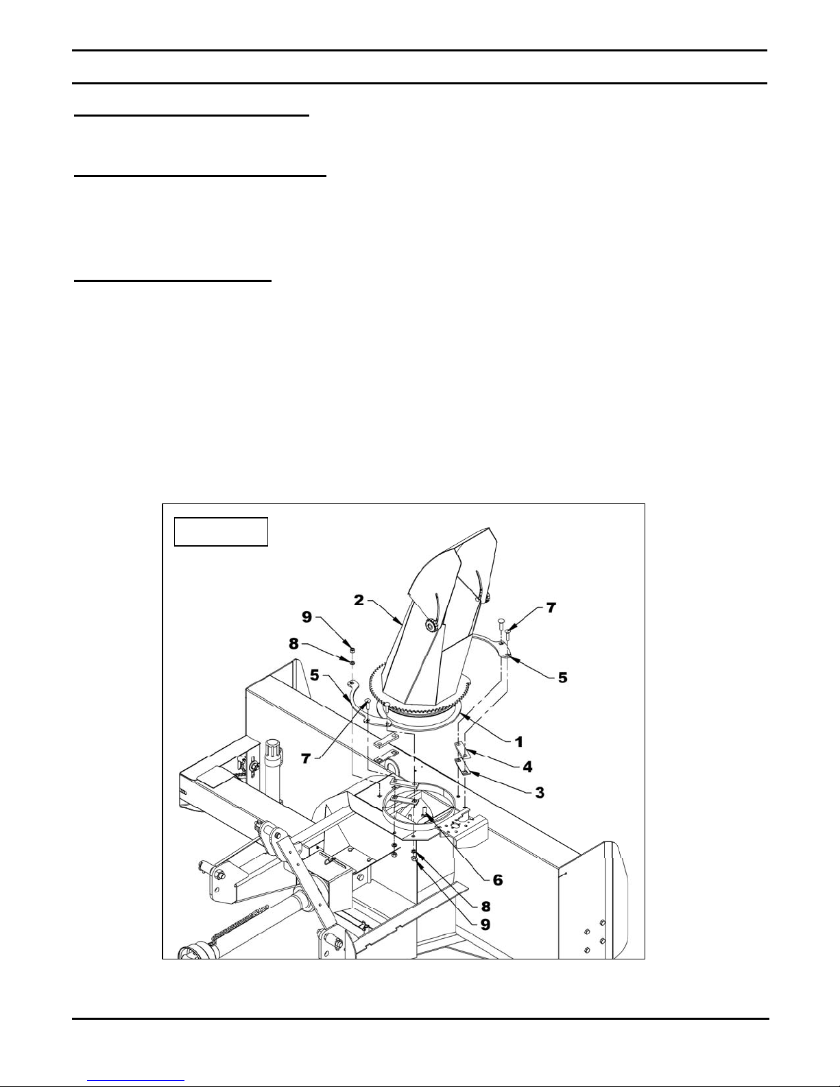
Installation of the Chute
(Figure 1)
1. Figure 1: Place the rotation bushing (item 1)
on the chute base of the snowblower.
2. Figure 1: Install the chute (item 2) over the
rotation bushing and install the three 3/16"
spacers (item 3) and the 3/8" spacers (item 4).
3. Figure 1: Insert the two three holes retaining
plates (item 5) by placing the large section
toward the support of the hydraulic motor.
Secure with two 1/2"NC x 3/4" carriage bolts
(item 7), upside down (front of the chute) and th e
four other bolts head up (rear of the chute).
Secure with six 1/2" lockwashers (item 8) and
four 1/2"NC hex nuts (item 9).
4. Tighten all bolts according to the Torque
Specification Table at the end of the manual.
Figure 1
OM 0410SB-A
13
Page 16
ASSEMBLY
Installation of Snowblower with Three Point Hitch
(Figure 2)
1. Install the two cat.1 pins (item 1) on the right
and left snowblower hitches in the lower holes
as shown on figure.
2. Category 1: Attach tractor lower links (ite m 2)
to the snowblower hitch pins (item 1) and
secure with the linchpins (item 3).
3. Category 2: Insert the 1 1/8" OD x 1 3/4" lg
bushings (item 9) on each pin (i tem 1). Attach
tractor lower links (item 2) to the snowblower
hitch pins (item 1) and secure with the
linchpins (item 3).
4. Category 1: Attach the tractor upper link
(item 4) between the upper attaching plates
(item 6) using the tractor pin and linchpin
(item 5 – not included).
5. Category 2: Insert a 1" OD x 2" lg bushing
(4600056) (item 10, not includ ed) on a 3 /4" dia.
x 5 7/16" lg pin (4600051) (item 5- not
included). Attach the tractor upper link (item 4)
between the upper attaching plates (item 6)
using the bushing, the pin and the tractor
linchpin (item 5 & 10 – not included).
6. Adjust the snowblower using the tractor upper
link so that the snowblower operates parallel to
the ground.
7. Set the tractor anti-sway turnbuckles so the
snowblower does not sway. Be sure there is
no contact with the tires.
8. Install the eyebolt (item 7) in the upper hole of
the left or right side of the three poi nt hitch by
screwing the eyebolt nut to the top and locking
eyebolt in place with a 3/8" serrated flang e nut
(item 8).
CAUTION
Before connecting snowblower driveline to
tractor drive shaft, make sure d riveline is not
too long in raised, lowered and middle
position. If the driveline is too long it mus t be
shortened, to avoid damaged to tractor. See
pages 26 to 28 for instructions.
Figure 2
OM 0410SB-A
14
Page 17

ASSEMBLY
Installation of Snowblower with Quick Hitch
(Figure 3)
CATEGORY 1 only
1. Install the two cat.1 pins (item 2) on the right
and left snowblower hitches in the upper
holes leaving 3 1/4" between the jam n ut and
the end of the pin as shown on figure.
2. Insert the two 2 1/8" lg bushings (item 3 ) on
each pin and lock in place with the two 7/16 "
linchpins (item 4).
3. Insert the 1 7/8" lg bushing (item 5) between
the upper attaching plates and lock in place
with the tractor hitch pin and a 7/16" linchpin
(items 6-7).
4. Install the eyebolt (item 8) in the upper hole of
the left or right side of the three point hitch by
screwing the eyebolt nut to the top and
locking eyebolt in place with a 3/8" serrated
flange nut (item 9).
CAUTION
Before connecting snowblower driveline to
tractor drive shaft, make sure driveline is
not too long in raised, lowered and middle
position. If the driveline is too long it must
be shortened, to avoid damaged to tractor.
See pages pages 26 to 28 for instructions.
Figure 3
OM 0410SB-A
15
Page 18

ASSEMBLY
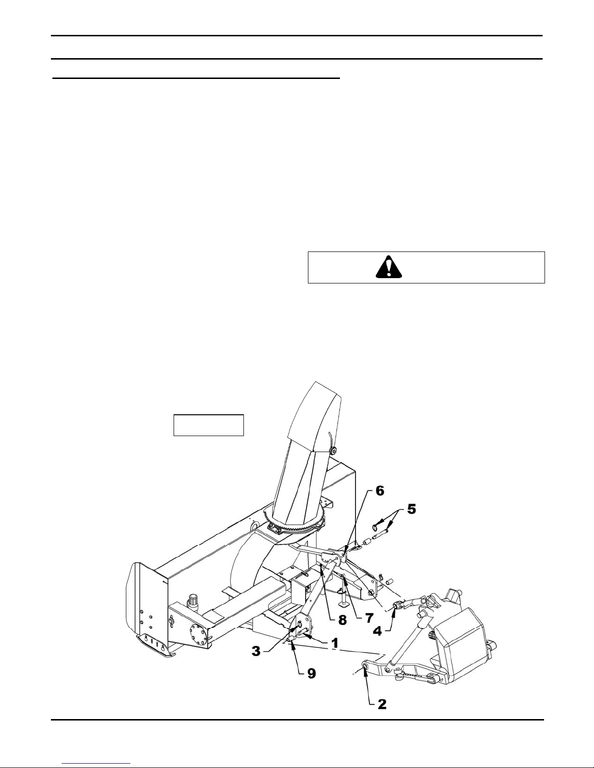
Installation of Manual Rotation Kit BER0077
(Figures 4-5-6-7)
: The rotation handle can be installed on
NOTE
the right or left side of the three point hitch.
1. Install the chute according to the instructions
contained in the snowblower Operator's Manual,
with the four 1/16" thick spacers provided with the
BER0077 kit.
2. Figure 4: Install the rotation tube support
(item 1) on the chute base. Secure using a
1/4"NC x 3/4" bolt, a 1/4" lockwasher and a
1/4"NC nut (items 6-7-8). Do not tighten.
3. Figure 4: Insert a 1 5/16" plastic bushing
(item 2) in the rotation tube support (item 1),
then insert the rotation worm (item 3).
4. Figure 4: Insert the other 1 5/16" plastic bushing
(item 5) in the rotation worm support (item 4),
and then slide on the rotation worm. Secure with
two 1/4"NC x 3/4" bolts and 1/4"NC nuts (items
9-10-11). Do not tighten.
5. Figure 5: Install the bracket (item 1) on the 3
point right or left hitch using two 3/8"NC x 1 1/4"
bolts, 3/8" lockwashers and 3/8"NC nuts (items
2-3-4). Tighten securely.
6. Figure 5: Install handle support bracket
(item 5) on the bracket (item 1) using a
3/4’’NC x 1 1/2’’ bolt, 3/4’’lockwasher and
3/4’’NC nut (items 6-7-8). Do not tighten.
7. Figure 5: Install the plastic grommet
(item 9) in the handle support (item 10).
8. Figure 5: Insert handle support (item 10)
inside the handle support bracket (item 5).
Fasten loosely with a 3/8"NC x 1/2’’ square
head set screw (item 11).
OM 0410SB-A
Figure 4 Figure 5
16
Page 19

ASSEMBLY
6Fig
9. Figure 6: Install plas tic handle (item 5) over the
rotation handle (item 6).
10. Figure 6: Insert assembled rotation tube
(item 1) inside the rotation worm assembly
(items 2). Align holes and insert a 10-24NC x 1’’
allen socket head capscrew (item 3) making
sure the capscrew sinks into the worm. Secure
with a nylon insert locknut (item 4). Adjust the
height of the handle support according to your
needs and shorten if necessary.
11. Figure 6: Insert the rotation handle (item 6)
inside the grommet and inside the ro tation tube
(item 1). Select desired length, align nearest
holes and secure with a 4mm x 80mm hairpin
(item 8).
12. Figure 7: Adjust the rotation tube support
(item 3) and the rotation worm support (item 1)
by moving them toward the chute so the
rotation worm is engaged between the gear
teeth of the chute. Make sure the rotation
worm and the bushings are well aligned.
Tighten slightly the three 1/4"NC x 3/4" bolts
and the three 1/4"NC nuts (item 2).
13. Figure 7: Rotate the chute completely to the
right then to the left using the rotation handle
(item 4).
• If th e chute is too hard to turn it's bec ause the
rotation worm is engaged too deep between
the gear teeth, move the worm slightly away
from the gear teeth and try again.
• If the chute rotates with difficulty because the
teeth do not engage or engage incorrectly,
adjust the rotation handle support toward the
chute and redo the steps.
14. Figure 7: Make sure the worm engages
completely when it reaches the end of the
chute gear. The rotation handle is well
adjusted when the chute rotates easily
without straining. Tighten firmly the three
1/4"NC x 3/4" bolts and the three 1/4"NC
nuts (item 5).
15. Figure 7: After the snowblower is mounted
to the tractor, you may adjust the rotation
handle position and height to a comfortable
and safe operating position. When the
desired position is set for working position,
make sure the rotation handle is not
interfering with any parts of the tractor while
on transport position (snowblower raised to
maximum). Tighten firmly the 3/8"NC x 1/2’’
square head setscrew 3/8"NC x 1/2"
(item 5) to the desired height. Then tighten
firmly the 3/4"NC x 1 1/2" bolt (item 6) to
the desired position.
16. Lubricate the rotation worm.
NOTE: To insure the manual rotation operates
properly, the handle support (fig.6, item 7) must
be positioned the closest possible to the top l ink
mounting point of the three point hitch while
making sure it does not come into contact with
the operator's seat when the snowblower is ful ly
raised.
CAUTION: To avoid personal
injury, check the full lifting range of the
snowblower, to ensure that the chute
rotation handle is clear of the operator ’s area
when the snowblower is in raised position.
OM 0410SB-A
Figure
ure 7
17
Page 20

ASSEMBLY
Installation of Hydraulic Rotation Kit BER0078
(Figures 8 to 12)
1. Install the chute according to t he instructions
contained in the snowblower Operator's
Manual.
2. Figure 10: Place the motor spacer (item 2) on
the motor top (item 1) by aligning the holes.
Install the motor (item 1) under the frame
base of the snowblower and secure with four
3/8’’NC x 1’’ bolts (item 3), four 3/8"
lockwashers (item 4) and four 3/8" (7/16"
hole) flat washers (item 5). Torque slightly.
3. Figure 10: Make sure the Woodruf key is on
the motor shaft and insert the motor gear
(item 6) on the shaft. Secure with a 1/4’’NC x
1’’ bolt (item 7), a 1/4" lockwasher (item 8)
and a 1/4" (5/16" hole) flat washer (item 9).
4. Figure 11: NOT INCLUDED
sealant, install a 1/4"NPT female x 1/2"NPT
male reducer (item 2), a male quick coupler
(item 3) and a dust cap (item 4) on each
straight end of the hoses (item 1).
: Using thread
CAUTION
To avoid serious personal injury. Escaping
hydraulic/ diesel fluid under pressure can
penetrate the skin causing serious injury.
• Do not use your hands to
check for leaks. Use a
piece of cardboard or
paper to search for leaks.
1. Hydraulic hose
2. Cardboard
3. Magnifying glass
• Stop engine and relieve pressure before
connecting or disconnecting lines.
• Tighten all connections before starting
engine or pressurizing lines.
• If any fluid is injected into the skin, obtain
medical attention immediately or gangrene
may result.
Figure 8
Figure 9
OM 0410SB-A
18
Page 21

5. Figure 10: Install a 0.052" flow
restrictor (item 2) in each motor input
(item 1).
6. Figure 10: NOT INCLUDED:
Connect the two hoses (item 3) on
the motor flow restrictors (item 2).
Direct the hose elbows toward the
snowblower upper arm.
7. Figure 10: NOT INCLUDED
hoses on the snowblower with
suitable bend, staying away from
sharp edges, nor compromise the
snowblower maintenance. Attach to
the right or left snowblower three
point arm with a hose clamp (item 4),
a 3/8"NC x 1 1/2" bolt (item 5) and a
3/8"NC nylon insert locknut (item 6).
8. NOT INCLUDED
tractor and make sure to raise and
lower the snowblower in extreme
positions, and check if hoses are
long enough to not interfere with any
parts. Attach hoses with nylon tie
wrap to appropriate places. Rotate
the chute to the right and to the left.
9. Figure 11: Motor adjustment
Push the motor toward the chute as
to well set the gear teeth (item 1)
without leaving any play between
teeth. Firmly tighten the four 3/8"NC
x 1" bolts (item 2). If the rotation do es
not operate correctly, redo the
adjustment.
10. Figure 11: Install the gear shield
(item 3) and secure with two 1/4"NC
x 3/4" bolts (item 4), two 1/4"
lockwashers and two 1/4"NC nuts
(items 5-6), as illustrated.
: Connect hoses to
: Run
:
ASSEMBLY
Figure 10
Figure 11
OM 0410SB-A
19
Page 22

ASSEMBLY
PROBLEM: HYDRAULIC CHUTE ROTATION IS SLOW OR DOESN'T TURN
When activating the chute rotation, it turns very slowly or not at all.
WARNING
To avoid serious personal injury
always wear safety glasses while doing the
instructions below.
SOLUTION:
1. Check if the tractor valve works well. Test
it by plugging another piece of equipment
to the valve. If it does not work well, refer
to the appropriate operator's manual.
2. Figure 12: Check if the chute itself rotates
well. To do so, remove the M6 x 1.00 x
10 mm serrated flange bolt (item 7) and
the motor gear (item 6) attached to the
motor shaft (item 4) and check if the chute
rotates well in both directions by turning it
by hand. If it does not rotate well, correct
the problem by checking if there is some
excess wear or debris locked between
components.
3. Figure 12: Check if there is residue in the
,
hydraulic circuit. To do so, first verify if the chute
rotates well in one direction. If so, remove the
1/4’’NC x 1’’ bolt (item 5), the 1/4" lockwasher
(item 4), the 1/4" flat washer (item 3)and the motor
gear (item 2) attached to the motor shaft (item 1)
and activate the rotation in the direction the motor
turns well for approximately 1 minute to evacuate
the residues. Then rotate the chute in the direction
it did not turn well and check if the problem is
resolved. - If not or if the chute does not rotate
well in either direction, disconnect the motor
hoses, remove the two flow restrictors (item 5)
attached to the motor inputs (item 2) and inspect
the holes of the two flow restrictors carefully.
Remove the residues if needed. If no residue is
present, disconnect hoses and clean them with
compressed air. - If the problem persists, check if
there is residue inside the motor (item 1). Clean
with compressed air the inside of the two motor
inputs. You can also manually turn the motor
shaft in both directions while shooting
compressed air.
Figure 12
IMPORTANT
always make sure to install the pl ugs and caps
on the hoses and tractor valve connectors.
This will prevent contamination of the
hydraulic circuit and obstruction of the flow
restrictor hole.
: When removing connectors,
OM 0410SB-A
20
Page 23

ASSEMBLY
Installation of Hydraulic Deflector BER0079A
(Figures 13 to 18)
1. Install the chute according to the instructions
in the snowblower Operator Manual.
2. Figure 13: Remove the two manual adjustment
knobs (item 1) and bolts (item 2) from each
side of deflector and replace with two 5/16” NC
x 3/4” carriage bolts (item 3), using original
nylon washers (item 5-6) and two 5/16" NC
nylon insert locknuts (item 4). Place one nylon
washer outside the deflector and one (item 6)
between the deflector and the chute base. Do
not tighten completely to allow deflector
movement by hand.
3. Figures 14 & 15: Place the deflector bracket
(item1) on center of chute deflector (item 2),
flush with bottom edge of deflector (detail A).
Using this bracket as a template, drill four 9/32"
holes into deflector.
4. Figure 15: Bolt in place with four 1/4" x 3/4"
allen flat socket head capscrews (item 3), 1/4"
lockwashers and 1/4"NC hex nuts (item 4),
with the capscrews heads inside the chute.
Tighten so that capscrews heads sink into
deflector surface.
Figure 13
Figure 14
5. Figure 15: Retract hydraulic cylinder rod
(item 5) completely and secure to deflector
bracket (item 1) and deflector base bracket
(item 6), using the two cylinder pins (item 7)
and the two cotter pins (item 8). Direct the
cylinder ports toward the snowblower center.
6. Figure 15: Open deflector to maxi mum so that
actuator rod retracts completely. Place
deflector base bracket (item 6) on the center
rear of chute and using the bracket as a
template, drill four 9/32" holes into chute.
7. Figure 15: Bolt deflector base bracket (item 6)
to chute using four 1/4" x 3/4" allen flat socket
capscrews (item 9), 1/4" lockwashers and
1/4"NC hex nuts (item 10), with the capscrews
heads inside the chute. Tighten so that
capscrews heads sink into chute base surface.
Figure 15
OM 0410SB-A
21
Page 24

ASSEMBLY
g
8
8. Figure 16: Install the hose support
(item 1) on the three point upper hitch
bracket (item 2) right or left (right one is
recommended) using two 3/8’’NC x
1 1/2’’ bolts (item 3) and two 3/8"NC
nylon insert locknuts (item 4).
9. Figure 16: With thread sealant, install a
90° 3/8” NPT male x 1/4” NPT swivel
female elbow (item 5) in each cylinder
port (item 6). Direct elbows upward by
placing the lower one so that the hose
does not interfere with the upper hose.
10. Figure 17: NOT INCLUDED
thread sealant, install a 1/4" NPT female
x 1/2" NPT male reducer (item 2), a
male quick coupler (item 3) and a dust
cap (item 4) on each hose straight end
(item 1).
11. Figure 18: NOT INCLUDED
the two hoses (item 1) to the cylinder
elbows (item 2).
NOTE: The figure 18 is a suggested
presentation for hose routing. In that
way, it prevents the hoses from getting
clamped in the chute gear. However,
other ways are also possible. In any
way, make sure there is enough play in
the hoses for the chute to rotate freely
from left to right without forcing on
hoses.
12. Figure 18: NOT INCLUDED
hoses on the snowblower with suitable
bend, staying away from sharp edges,
nor compromise the snowblower
maintenance. Attach to the hose
support (item 3) with a hose clamp
(item 4), a 3/8’’NC x 1 1/2’’ bolt (item 5)
and a 3/8"NC nylon insert locknut
(item 6) in the hole that fits your needs.
13. NOT INCLUDED
tractor and make sure to raise and lower
the snowblower in extreme positions,
and check if hoses are long enough to
not interfere with any parts. Attach
hoses with nylon tie wrap to appropriate
places. Move the deflector from top to
bottom to verify operation.
: Connect hoses to
: With
: Connect
: Run
CAUTION
To avoid serious personal injury. Escaping
hydraulic/ diesel fluid under pressure can penetra te
the skin causing serious injury.
• Do not use your hands to
check for leaks. Use a piece of
cardboard or paper to search
for leaks.
1. Hydraulic hose
2. Cardboard
3. Ma
nifying glass
• Stop engine and relieve pressure before
connecting or disconnecting lines.
• Tighten all connections before starting engine
or pressurizing lines.
• If any fluid is injected into the skin, obtain
medical attention immediately or gangrene ma y
result.
Figure 16
.
Figure 17
OM 0410SB-A
Figure 1
22
Page 25

ASSEMBLY
Installation of Electric Deflector Kit 8151
(Figures 19 to 21 & Electrical Diagram)
PRE-ASSEMBLY
1. Figure 19A: Install the clevis with the 1 1/32"
diam. hole (item 1) on the actuator base
(item 2), and the one with the 1 5/32" diam.
hole (item 3) on the other end and attach
using two 1/2" NC x 2 1/2" bolts and two 1/2"
NC nylon insert locknuts (items 4-5).
2. Figure 19A: Install a 3/16" x 1 3/4" spring pin
(item 6) on each 1" pin (item 7).
3. Figure 19 & diagram: Connect the wires to
the switch as follows:
• 72" black ground wire (item 1) to terminal
"C" (see diagram).
• 72" red fuse wire (item 3) to terminal "B
(see diagram).
• 360" red and black actuator wires (item 4)
to terminal "A" and "D" (see diagram).
Diagram
OM 0410SB-A
Figure 19 Figure 19A
23
Page 26

ASSEMBLY
ASSEMBLY
For Chute with knob adjustment:
1. Figure 20: Remove the two manual
adjustment knobs and the bolts on each
deflector side (item 11) and replace with two
5/16” NC x 3/4” carriage bolts (item 1), the
original nylon insert locknuts (item 2) and
two 5/16"NC nylon insert locknut (item 3).
Leave a 1/16" play.
2. Figure 20: Place the deflector bracket
(item 5) in the middle of the chute deflector,
and align with the bottom edge of the
deflector. Using the bracket as a template,
drill four 1/2" holes in the deflector.
3. Figure 20: Secure in place with four
5/16" NC x 3/4" allen flat head setscrews
(item 4) and 5/16" serrated flange nuts
(item 6), placing the setscrew head inside
the chute. Tighten until the setscrew head
sinks into the inside surface of the deflector.
4. Figure 20: Retract completely the preassembled actuator rod (item 10). Attach the
actuator to the deflector bracket (item 5) and to
the base bracket (item 7), with two 1" pins
(item 8) and secure with two hairpins (item 9).
5. Figure 20: Open deflector completely, making
sure the actuator is completely closed. Place
the base bracket (item 7) in the rear center of
the chute. Using the bracket as a template,
drill four 1/2" holes in the chute.
6. Figure 20: Attach the base bracket with four
5/16" allen flat head setscrews (item 4) and
5/16" serrated flange nuts (item 6) placing the
setscrew head inside the chute. Tighten until
the setscrew head sinks into the inside surface.
For Chute with telescopic adjustment rod:
Figure 20A: Install the pre-assembled actuator
(item 10) on the chute in the illustrated position
with two 1" pins (item 8) and secure with two
4mm x 80mm hairpins (item 9).
Figure 20 Figure 20A
OM 0410SB-A
24
Page 27

ASSEMBLY
7. Figure 21: Insert the switch (item 1) in the
switchbox (item 2), secure with the two
nuts (items 3) provided with the switch,
and screw the rubber cap (item 4) in the
order shown on figure. Insert the plastic
cap (item 5) in the free hole of the
switchbox (if needed).
8. Figure 21: Install the switchbox at a
convenient location for easy access when
operating the snowblower. Secure using
three #10 x 1/2" self-drilling screws
(item 6). Leave a hole to install the ground
wire. Avoid placing the switch box where
wires are already installed as they could
be damaged.
9. Figure 19: Connect the ring terminal of the
ground wire (item 1) to a ground screw of
the vehicle.
10. Figure 19: Connect the fuse wire (item 3)
to the tractor switch wire using a tap
connector (item 5).
11. Figure 19: Connect the actuator double
wire (item 4) to the actuator (item 7).
12. Figure 19: Cover all wires with the loom
(item 6) and attach with tie wrap.
Figure 21
OM 0410SB-A
25
Page 28

ASSEMBLY
IMPORTANT:
A proper initial installation will give you years of
satisfactory service on your equipment. Please
read carefully following instructions that have
been specially included to help you and ensure
you are satisfied with your purcha se.
WARNING
Unfortunately, snowblowers will be faced
with forgotten or hidden objects under the
snow, such as : chain, tires, stones, pieces
of wood, etc. In spite of all our efforts,
machines are not built to resist all those
conditions.
How to Determine Driveline Angles
IMPORTANT: To obtain the proper universal
joint angles, it is recommended to adjust the
three point hitch at the furthest point from the
tractor recommended by the manufacturer
Angles of Driveline Joints Too Larg e
Avoid
Danger: Tractors Too Big
It is dangerous to use a tractor that is too big an d
powerful. The tractor will always be able to
overload the blower, even if the machine is
already at maximum capacity. Furthermore,
tractors being very high, the driveline angles will
be excessive which means the universal joints
will be very vulnerable and the life of the driveline
will be dramatically reduced.
The universal joint angle is directly related with
the life of driveline. In order to reduce the angle, it
is necessary to increase the distance between
the snowblower and the t racto r.
Reasonable Angles of Driveline Joints
Acceptable
OM 0410SB-A
26
Page 29

ASSEMBLY
Unequal Angles at Driveline Joints
Avoid
Angles at Each End of Driveline
A popular habit is to change the snowblower
angle in order to obtain a better scraping effect.
This practice can become harmful to the
driveline since the angle at each end is
unequal. This results in a fan speed variation as
well as a drastic increase of load on cross and
bearings. To be avoided: It is recommended to
always keep tractor driveline and snowblower
input shaft parallel.
Equal Angles at Driveline Joints
Recommended
Determining Driveline Length
IMPORTANT
make sure the driveline is not too long. At
working position, the two half drivelines must
intersect each other sufficiently to insure
maximum efficiency but there must not be any
interference.
1. To determine the "L" length for your tractor
model first find the "X" factor (figure 22) by
measuring the horizontal distance between
the end of the tractor's drive shaft and the
end of the snowblower's driven shaft when
the snowblower is in transport position as
shown on figure.
2. Choose in the table below the "Y" factor
according to the tractor category an d deduct
that number from "X" (figure 22) to determine
"L" (figure 23) which is the center-to-center
length between the universal joints.
: Before using the equipment,
Figure 22
L = X – Y
3 PTS HITCH
CATEGORY
Cat. 1 4 1/2"
Cat. 2 5 1/2"
Y
OM 0410SB-A
27
Page 30

ASSEMBLY
A
NOTE:
intersect by at least 7 3/4" when in working
position that is when the snowblower rests on the
ground.
3. Figure 23: Hold the two half-shaft side by
4. Figure 23A: Cut off inner and outer guard
5. Figure 23A: Cut the guard a second time
Before cutting, make sure the two sha fts
side and locate the "L" length between the
two center-to-center half-shaft universal
joints. Mark off the zone to be cut on both
halves opposite each half-shaft guard as
shown on Figure.
tubes as well as the inner and outer
telescopic sections.
leaving the same distance between the end
of the guard and the end of the shaft as
existed before. To obtain the proper d ista nce
"A" shown on Figure 23A cut the guard
according to the following table:
DISTANCE A
Male PTO Female PTO
1 3/4" 1 1/4"
6. Figure 23A: File down tubes and remove
chips.
7. Apply grease to inside of outer telescopic
section.
IMPORTANT
only.
: Work with fully guarded shafts
Figure 23A
OM 0410SB-A
Figure 23
28
Page 31

ASSEMBLY
Driveline Installation
(Figure 24)
1. Separate the snowblower from the three
point or quick hitch.
2. Remove paint from snowblower gearbox
shaft (item 1) and grease driveline sliding
surfaces and yoke (item 2).
3. Remove the bolts (items 3) from the driveline
yoke (item 2) and slide yoke over drive shaft
using the sliding action of the driveline. Make
sure the driveline is well secured to the shaft
by reinstalling the bolts and nuts (item 3-4) in
the order shown. Tighten the bolts according
to the Torque Specification Table at the
end of manual.
4. Attach safety chain (item 5) around the upper
link (item 6) to prevent the guard from
spinning.
Figure 24
OM 0410SB-A
29
Page 32

ASSEMBLY
Removing Snowblower from Tractor
(Figures 25 to 28)
Three Point Hitch
1. Set parking brake and turn engine off.
2. Figure 25: Remove the wire round lock pin
(item 2), lower the parking stand (item 1)
completely to the ground to release all
pressure from the three-point and reinsert the
wire round lock pin in the lower hole (item 3).
3. Figure 26: Detach upper link (item 4) by
removing linchpin and pin (items 6-5).
4. Figure 26: Disconnect driveline from tractor
and attach the driveline safety chain (ite m 7) to
the three point hitch eyebolt (item 8) .
5. Figure 26: Carefully detach lower links
(items 2) from hitch pins (item 1) by removing
linchpins (items 3), loosen anti-sway
turnbuckles and slowly back tractor away from
the snowblower.
IMPORTANT
snowblower, retorque all b olts after the first 10
hours of operation.
: To avoid damages to the
Figure 25
Figure 26
OM 0410SB-A
30
Page 33

ASSEMBLY
Quick Hitch
1. Set parking brake and turn engine off.
2. Figure 27: Remove the wire round lock pin
(item 2), lower the parking sta nd (item 1) and
reinsert the wire round lock pin in the lower
hole (item 3).
3. Figure 28: Disconnec t driveline (item 1) from
tractor and attach the driveline safety chain
(item 2) to the three point hitch eyebolt
(item 3).
4. Figure 28: Slowly back the tractor away to
release quick hitch (item 4) from the
snowblower.
Figure 27
Figure 28
OM 0410SB-A
31
Page 34

OPERATION
GENERAL PREPARATION
1. Read the operator’s manual carefully before
using the tractor and snowblower. Be
thoroughly familiar with the controls and
proper use of the equipment. Know how to
stop the unit and disengage the controls
quickly.
2. Make sure the snowblower is clear of snow
before engaging the driveline.
3. Make sure the auger and fan operate freely.
4. Check the oil level in the worm Gearbox and if
necessary, add 80W90 SAE gear oil, AGMA
5EP oil or equivalent.
5. Check the t wo shear bolts, one on the driving
shaft, and the one on the PTO, for proper
tightness.
6. Adjust so that the snowblower skid shoes run
level.
7. Wear adequate winter outer garments while
operating equipment.
OPERATING CONTROLS
Work and Travel Speed
Working ground speed will depend on the depth
and density of the snow to be cleared. Normally,
ground speed will range from 4 to 7 MPH for light ,
dry snowfalls 3 to 6 inches, and 1 t o 3 MPH for
heavy, wet or drifted snow. To transport,
disengage the drive shaft and raise the
snowblower to full transpor t he ight.
Raising and Lowering the Snowblower
Move the three point lever on right hand side of
seat down or forward to lower, and up or rearward
to raise.
ADJUSTMENTS
Chain Tension Adjustment
(Figure 29)
The premature wear of the chain may be caused by
tension being too tight. It is therefore import ant not to
tighten chain to its maximum.
• To adjust the tension on the drive chain, loosen the
bolt (item 1), securing the idler sprocket to the
snowblower housing.
• To tighten the chain, lower the bolt. Leave
approximately 1/8" deflection in one span of the
chain. Retighten securely the bolt holding the idl er
sprocket.
Skid Shoe Adjustment
(Figure 29)
Adjust the skid shoes so that the snowblower runs
level and according to the surface conditions so that
stones are not thrown with the snow .
Adjust both skid shoes to the same height to keep the
cutting edge level and adjust upwards for smooth
surfaces.
Loosen skid shoe bolts (item 2) and adjust according
to instructions below, and securely tighten bolts:
Clearance between cutting edge and surface:
• Paved surface: Insert bolts in lower hole.
• Uneven or gravel surface: Insert bolts according to
distance needed: 1/2" - middle hole
1" - upper hole
WARNING
To avoid personal injury, be sure the tractor
engine is off, the drive shaft disengaged, and
all movement has stopped before making any
adjustments.
OM 0410SB-A
Figure 29
Manual Deflector Adjustment
Set the angle of deflection according to the dis tance
the snow must be thrown. To set the deflector a ngle,
loosen the deflector knobs located o n the side of the
deflector and adjust the deflector to the appropriate
angle. Retighten the knobs.
32
Page 35

OPERATION
SNOW REMOVAL METHODS
When removing snow, do not use the sno wblower as a dozer blade to push snow. Let the snowblower
work its way through deep drifts. If the speed of your tractor is too fast, the snowblower may become
overloaded and clog. For best results, raise the snowblower and remove a top layer of snow. A second
pass with the snowblower will remove the remaining snow.
IMPORTANT
: Use full RPM power when removing wet, sticky snow. Low RPM power wil l tend to clog the
chute.
WARNING
Do not use hands or feet to unclog chute. Do not attempt to clear clogged chute of snow while tractor
engine is running. If the chute clogs, disengage the drive shaft, shut off the tractor engine, remove the
ignition key, wait for all movement to stop, and then clear the snow from the chute.
A definite pattern of operation is required to thoroughly clean the snow area. These patterns will avoid
throwing snow in unwanted places as well as eliminating a second removal of snow
Where it is possible to throw the snow to the left
and right (above), as on a long driveway, it is
advantageous to start in the middle. Plow from
one end to the other, throwing snow to both sides
without changing the direction of the discharge
guide
OM 0410SB-A
If the snow can only be thrown to one side of the
driveway or sidewalk (above), start on the opposite
side. At the end of the first pass, rotate the
discharge guide 180 degrees for the ret urn pass.
At the end of each succeeding pass, rotate the
discharge guide 180 degrees to mai ntain direction
of throw in the same area.
33
Page 36

MAINTENANCE
MAINTENANCE
Shearbolts
Check the shearbolts indicated on the figure
below at frequent intervals for proper tightness t o
be sure the blower is in safe working condition.
Figure 30: To access the shear bolts, pull up the
access pannel (item 1) located near the chain. If
the shearbolts need replacement, use the
following parts only:
WARNING
Provide adequate blocking before working
under the snowblower when in the raised
position.
Driveline
Drive shaft
Shearbolt hex. 1/4" NC x 1 1/4" gr.2, incl. nut.
Part # 669345.
Driveline
Shearbolt M8 x 1.25 x 50mm gr.8.8 and nut. Pa rt
# 4700060.
:
:
IMPORTANT: When the snowblower is not
used for more than two weeks, perform
driveline maintenance and alwa ys store it i n a
dry place, away from bad weather conditions.
ACCESS
Figure 30
OM 0410SB-A
SHEAR BOLT
34
Page 37

MAINTENANCE
LUBRICATION
Use oil or a grease gun and lubricate as follows:
DESCRIPTION INTERVAL LUBRICATION REQUIRED
8 hours
Driveline
16 hours Oil the push pins
Grease each universal joint. Separate the sliding
parts and cover each one of them with grease
Chain
Drive Shaft 24 hours of operation Grease fitting on shear plate
Gearbox
Bearing 24 hours of operation Grease each auger and drive shaft bearing
and after each operation
4 hours
Every month
Once a y ea r Replace oil
Lubricate with chain lube
Check oil level. If needed, add AGMA 5EP extreme
pressure oil, SAE 80W90 gear oil or equivalent.
OM 0410SB-A
35
Page 38

MAINTENANCE
DRIVELINE TROUBLESHOOTING
QUICK-DISCONNECT YOKE
AVOIDABLE DAMAGES POSSIBLE CAUSES CORRECTIVE ACTIONS
Quick-disconnect pin tight or
completely seized.
Quick-disconnect pin
damaged (broken or bent)
Quick-disconnect pin
damaged in the locking
portion.
Quick-disconnect pin dirty
(insufficient maintenance).
Quick-disconnect pin
defective (forced
engagement, incorrect
handling)
Excessive shaft leng th.
Axial loads too high.
Note: Quick-disconnect pins must be cleaned and greased every 16 hours.
YOKE
AVOIDABLE DAMAGES POSSIBLE CAUSES CORRECTIVE ACTIONS
Yoke ears deformation
Excessive shaft leng th.
Axial loads too high.
Excessive working angle
and torque.
Clean, oil and follow service
instructions.
Replace quick-disconnect pin.
Shorten shaft length (cut both
telescopic tubes as well as
shield and remove burrs).
Replace quick-disconnect pin.
Clean and grease telescopic
tubes, and replace both tubes,
if necessary.
Replace quick-disconnect pin.
Shorten shaft length (cut both
telescopic tubes as well as
shields and remove burrs).
Replace defective yokes.
Clean and grease telescopic
tubes, and replace bot h tubes,
if necessary.
Replace defective yokes.
Verify compatibility between
shaft and working conditions
(torque vs. angle).
Disengage tractor driveline
during cornering or when lifting
or lowering the implement.
Change to a larger driveline
size.
Replace defective yokes.
Yoke ears distorted. Overload caused by high
Yoke ears worn or pounded.
OM 0410SB-A
Engage driveline more
starting and peak torques.
Excessive working angle. Avoid excessive working
carefully.
Use appropriate safety
devices.
Replace defective yokes.
angle.
Disengage tractor driveline
during cornering.
Replace defective yokes.
36
Page 39

MAINTENANCE
AVOIDABLE DAMAGES POSSIBLE CAUSES CORRECTIVE ACTIONS
CROSS KIT
Cross arms broken.
Bearing caps turning in their
cross journal.
Overheated bearing caps.
Accelerated wear of cross kit.
Extreme torque peak or
shock load.
Axial loads too high.
Excessive continuous
torque and/or excessive
working angle.
Inadequate greasing.
Excessive continuous
torque and/or excessive
working angle.
Inadequate greasing.
Use appropriate safety device.
Change to a larger driveline
size.
Shorten driveline shaft.
Replace defective cross
bearings.
Verify compatibility between
shaft and working conditions.
Carefully follow greasing
instructions.
Replace defective cross
bearings.
Verify compatibility between
shaft and working conditions.
Carefully follow greasing
instructions.
Replace defective cross
bearings.
Note: Cross bearings must be greased every 8 working hours.
AVOIDABLE DAMAGES POSSIBLE CAUSES CORRECTIVE ACTIONS
TELESCOPIC TUBES
Telescopic tubes failure or
twisting.
Extreme torque peak or
shock load.
Short tube engagement.
Use appropriate safety device.
Change to a larger driveline
size.
Replace the driveline drive
shaft with one having
adequate length.
Replace defective tubes.
Note: Telescopic tubes must be cleaned and greased every 8 working hours.
Accelerated wear of telescopic
tubes.
Extreme load when sliding.
Short tube engagement.
Inadequate greasing.
Dirt
Change to a driveline with
rilsan coated inner tube.
Replace the driveline with one
having adequate length.
Carefully follow greasing
instructions.
Replace defective tubes.
OM 0410SB-A
37
Page 40

MAINTENANCE
SHIELD
AVOIDABLE DAMAGES POSSIBLE CAUSES CORRECTIVE ACTIONS
Excessive wear of shield
bearings.
Chain moving or failure.
Shield cone damaged.
Shield tubes damaged
(deformed and split at one
side).
Insufficient lubrication.
Incorrect chain mounting.
Shield interfering with
implement.
Shield interfering with
implement.
Incorrect chain mounting.
Shield cone in contact with
components on the tractor
and/or implement.
Excessive angularity.
Shields in contact with
components on the tractor
and/or implement.
Shield tubes overlap too
short or no overlap at all
with extended driveline.
Follow lubrication instructions.
Mount chain to allow
maximum angularity.
Avoid contact of the shields
with fixed parts of the machine
or tractor.
Replace shield bearings.
Avoid contact of the shields
with fixed parts of the machine
or tractor.
Mount chain to allow
maximum angularity.
Replace defective parts.
Eliminate interference
between Shield cones and any
part on the tractor and/or
implement.
Avoid excessive angle during
cornering or when lifting or
lowering the implement.
Replace damaged Shield
cones.
Eliminate interference
between Shield cones and
any part on the tractor and/or
implement.
Replace damaged tubes.
Adjust Shield tubes length
with longer tubes.
Note: Shield bearings must be greased every 8 working hours.
OM 0410SB-A
38
Page 41

PARTS
I
NTRODUCTION
All parts are illustrated in "exploded views" which show the individual parts in their normal relationship to
each other. Reference numbers are used in the illustrations . These numbers correspond to those in the
"Reference Number" (REF) column, and are followed by the description and quantity required.
Right Hand and Left Hand are determined by those seen by the conductor standing behind the equipment.
The manufacturer reserves the rights to change , modify, or eliminate from time to time, for technical or
other reasons, certain or all data, specifications, or the product or products themselves, without any liability
or obligation.
The parts listed here are available through your local dealer.
MANUAL HOLDER – ALL MODELS
EF. DESCRIPTION QTY PART #
R
1 Manual holder 1 4200030
2 Bolt hex. 5/16" NC x 3/4" lg gr. 5, PTD 2 0100018
3 Nut nylon insert 5/16" NC, PTD 2 1000005
OM 0410SB-A
39
Page 42

SNOWBLOWER – B74C
PARTS
OM 0410SB-A
40
Page 43

PARTS
SNOWBLOWER – B74C
REF. DESCRIPTION QTY PART #
1 Housing (without gearbox) 1 670790
2 Chute (including decals) 1 669782
3 Knob 2 657309
4 Spacer 3/8" thick x 1.25" larg. x 4.5 lg 3 669178
5 Spacer 3/16" thick x 1.25" larg. x 4.5 lg 3 669179
6 Retaining plate 2 665935
7 Carriage bolt 1/2" NC x 1 3/4" gr.5 PTD 6 0300025
8 Auger 1 666271
9 Round wire lock pin 1/4" x 2" PTD 1 1900006
10 Lockwasher 5/8" PTD 1 1200007
11 Nut hex. 5/8" NC gr.5 PTD 1 0900007
12 Rotation bushing 1 662834
13 Bolt hex. 3/8" NC x 3/4" lg gr.5 PTD 4 0100037
14 Drive shaft 1 669720
15 Serrated flange nut 3/8" NC PTD 1 0900035
16 Eyebolt 3/8" NC x 4" lg w/ nut 1 0400027
17 Bolt hex. 3/8" NC x 1 1/2" gr.5 PTD 5 0100040
18 Lockwasher 3/8" PTD 13 1200004
19 Flat washer 3/8" 1 1400003
20 Fan washer 1 661554
21 Fan 1 668966
22 Key 3/8" x 3/8" x 2 3/4" lg 1 654174
23 Driveline Series 40 1 4700159
24 Driveline shield bracket 1 668097
25 Hairpin 3mm x 65mm lg PTD 1 1800004
26 Driveline shield 1 668057
27 Bolt hex. 3/8" NC x 5" gr.5 PTD 4 0100051
28 Nut hex. 3/8" NC gr.5 PTD 12 0900003
29 Spacer plate 1 669722
30 Shear plate 1 669595
31 Oilite bushing 1 4300072
32 Shearbolt 1/4"NC x 1 1/4" gr.5, incl. nut 1 669596
33 Driving shaft support 1 669356
34 Grease fitting 1/4" NF 2 654106
35 Parking stand 1 668053
36 Bolt hex. 5/16" NC x 3/4" lg gr.5 PTD 1 0100018
37 Bolt hex. 1/4" NC x 1 1/4" gr. 5 PTD 1 0100005
38 Nylon insert locknut 5/16 NC PTD 1 1000005
39 Gearbox 1 663485
40 Bushing 1 1/8" ext. x 1 3/4" lg PTD 2 4600045
41 Linchpin 7/16" PTD 2 1900003
42 Hitch pin 7/8" x 5 1/2" lg Cat. 1 2 654196
43 Chain #60 x 78 links 1 654009
OM 0410SB-A
41
Page 44

PARTS
SNOWBLOWER – B74C
EF. DESCRIPTION QTY PART #
R
44 Coupling link #60
45 Spacer ring .656"ID x 1.760 x 1" ext. 1 668093
46 Idler sprocket 60A12 1 3300022
47 Spacer ring .656"ID x .807 x 1" ext. 1 667777
48 Carriage bolt 5/16" NC x 1" gr.5 PTD 2 0300003
49 Carriage bolt 1/2" NC x 1" lg gr.5 PTD 4 0300022
50 Adjustable skid shoe 2 669586
51 Nylon flat washer 7/16" hole 2 658468
52 Flange bearing 1 1/4" hole, 4 holes 3 4300118
53 Lockwasher 1/2" PTD 18 1200006
54 Nut hex. 1/2" NC PTD 22 0900006
55 Nylon flat washer 11/32" hole 4 658467
56 Sprocket 60A32 1 654167
57 Access plate 1 669597
58 Bolt hex. 1/2" NC x 1 1/2" lg gr.5 PTD 12 0100070
59 Bolt hex. 5/8" NC x 4 1/2" lg gr.5 PTD 1 0100104
60 Flat washer 5/8" (11/16" dia. trou) 2 1400008
61 Nylon insert locknut 1/4"NC PTD 1 1000003
1
654839
OM 0410SB-A
42
Page 45

PARTS
GEARBOX 663485
REF. DESCRIPTION QTY PART #
1 Casing 2 659848
2 Bearing 2 659844
3 Shim 1 656649
4 Input shaft 1 664663
5 Shim 2 659855
6 Oil seal 3 659852
7 Snap ring 2 656652
8 Gear 2 662236
9 Parallel key 2 659850
10 Output shaft 1 659853
11 Bearing 2 659844
12 Plug 1 659847
13 O-ring 1 661144
14 A l l e n s o c k e t he a d c a p s cr e w M 8 x 1 . 2 5m m x 5 5 mm – 8 . 8 . 8 0800032
15 Stover l ocknut M 8 x 1.25mm - 8 8 0900063
16 Shim 1 659854
OM 0410SB-A
43
Page 46

PARTS
DRIVELINE 4700159
EF. DESCRIPTION QTY PART #
R
1 Yoke ass'y 1 660764
2 Journal cross 2 660765
3 Yoke for female tube 1 663189
4 Female tube 1 4700160
5 Male tube 1 4700161
6 Yoke for male tube 1 663193
7 Yoke ass'y 1 4700058
8 Bolt M12 x 1.25 x 70 with nut 2 662199
9 Grease fitting 1 663129
10 Ball Ø1/4" 23 663163
11 Shear bolt 8mm x 1.25 x 50 gr.8.8 and nut 1 4700060
12 Protector and chain 1 4700164
13 Pin for outer tube 1 4700061
14 Pin for inner tube 1 4700062
OM 0410SB-A
44
Page 47

PARTS
A
BER0077 - MANUAL ROTATION
EF. DESCRIPTION QTY PART #
R
1 Rotation handle 1 667425
2 Rotation tube 1 660188
3 Rotation yoke 1 659595
4 Universal block 1 658193
5 Rotation worm 1 665953
6 Rotation worm support 1 665952
7 Spring pin 1/4" x 1 1/4" 2 1600015
8 Hairpin 4mm x 80mm, PTD 1 1800002
9 Plastic handle 1 656797
10 Bushing 1 5/16" lg 2 657335
11 Hex. nut 1/4"NC, PTD 3 0900058
12
13 Nylon insert locknut 10-24 NC, PTD 1 1000002
14 Handle support 1 660187
15 Handle support bracket 1 660269
16 Hex. bolt 3/8"NC x 1 1/4" gr. 5, PTD 2 0100039
17 Hex. nut 3/8"NC PTD 2 0900003
18 Lockwasher 3/8", PTD 2 1200004
19 Setscrew 3/8"NC x 1/2", square head 1 0600006
20 Plastic Grommet 1 657390
21 Bracket 1 660388
22 Hex. bolt 3/4"NC x 1 1/2" gr. 5, PTD 1 0100115
23 Lockwasher 3/4", PTD 1 1200008
24 Hex. nut 3/4"NC, PTD 1 0900008
25 Rotation tube support 1 665951
26 Hex. bolt 1/4"NC x 3/4" gr. 5, PTD 3 0100003
27 Lockwasher 1/4", PTD 3 1200002
28 Spacer for retaining plate 1/16" th 4 666191
llen socket head capscrew 10-24NC x 1" gr. 5 1 0800009
For the Chute Installation
OM 0410SB-A
45
Page 48

PARTS
BER0078 - HYDRAULIC ROTATION
R
EF. DESCRIPTION QTY PART #
1 Hydrauli c m otor 50 c c 1 3910092
- Seal K i t 1 3910093
2 Key 1/4" x 1" w o o d r u ff (incl. i n 39 1 0 0 9 2 ) 1 659191
3 Motor gear 1 669705
4 Flow restrictor 0.052" 2 664362
5 Rubber hos e 1 /4 " x 7 5 " lg . 2 666583
6 Reducer 1 / 4 "NPT fem ale x 1/ 2 " NPT mal e 2 0100040
7 Male quick co upler 2 1000006
8 Dust cap 2 2100009
9 Flat wash e r 1/4" ( 5 / 1 6" hole) PTD 1 1400002
10 Lockwas h er 1/4" P T D 3 1200002
11 Gear shield 1 669715
12 Bolt hex . 1/4"NC x 3/4" PT D 3 0100003
13 Bolt hex . 3/8"NC x 1" PTD 4 0100038
14 Lockwas h er 3/8" P T D 4 1200004
15 Flat washer 3/8 " (7/16" h o le) PTD 4 1400004
16 Motor spacer 1 669718
17 Nut hex. 1/4"NC PTD 2 0900001
OM 0410SB-A
46
Page 49

PARTS
BER0079A - HYDRAULIC DEFLECTOR
R
EF. DESCRIPTION QTY PART #
1 Allen socket head capscrews 1/4" x 3/4" PTD 8 0800050
2 Lockwasher 1/4" PTD 8 1200002
3 Nut hex 1/4" NC P TD 8 0900001
4 Carriage bolt 5/16" NC x 3/4" Gr.5 PTD 2 0300002
5
Elbow 90° 3/8" NPT STM x 1/4" NPT SWF
6 Deflector bracket 1 669979
7 Deflector base bracket 1 669980
8 Cylinder & pins ass'y 1 665433
- Se a l kit 1 665434
9 - Cotter pin 3/16" x 1 1/2 " PTD 4 1500013
10 - Pin 3 / 4 " x 2 1 / 2 " P TD 2 665235
11 Hose support 1 669031
12 Hose clamp 1 666583
13 Bolt hex . 3/8" NC x 1 1/2" P T D 3 0100040
14 Nylon insert lo cknut 3/ 8 " NC PTD 3 1000006
15 N y l o n i n se r t l o c k n u t 5 / 1 6 " NC PTD 2 1000005
16 Nylon ti e wrap1/ 4" x 15" lg. 2 2100009
2 654438
OM 0410SB-A
.
47
Page 50

PARTS
8151- ELECTRIC DEFLECTOR
P
REF. DESCRIPTION QTY
1 Actuator 1 662983
2 Switchbox 1 666048
3 Switch 1 663383
4 Rubber cap 1 658666
5 Plastic cap 1 662530
6 Clevis – rod 1 666049
7 Clevis – base 1 666050
8 Pin 1" 2 666057
9 Ground wire 72" (black) 1 666054
10 Tap connector 1 656665
11 Fuse wire72" (red) 1 666055
12 Actuator wire assembly 1 666056
13 Spring pin 3/16" x 1 3/4", black 2 1600009
14 Hairpin 4mm x 80mm, PTD 2 1800002
15 Self-drilling screw #10 x 1/2" 4 3200011
16 Bolt hex. 1/2"NC x 2 1/2", PTD 2 0100076
17 Nylon insert locknut 1/2"NC, PTD 2 1000011
18 Loom 3/8" x 420" 1 666053
19 Nylon insert locknut 5/16"NC, PTD 2 1000005
20 Nylon insert locknut 8" lg x 4 mm 5 2100003
21 Deflector bracket 1 669826
22 Base bracket 1 669825
23 Allen setscrew, flat head 5/16"NC x 3/4" 8 0700003
24 Serrated flange nut 5/16"NC, PTD 8 0900036
25 Carriage bolt 5/16"NC x 3/4" PTD 2 0300002
ART #
OM 0410SB-A
48
Page 51

TORQUE SPECIFICATION TABLE
GENERAL SPECIFICATION TABLE
U
SE THE FOLLOWING TORQUES WHEN SPECIAL TORQUES ARE NOT GIVEN
Note:These values apply fasteners as received from supplier dry, or when lubricated with normal engine oil. They do not apply if
special graphited or moly sidulphide greases or other extreme pressure lubricants are used. These values apply to dry
conditions; under lubricated conditions reduce by 25% the torque s in this table.
BOLT HEAD IDENTIFICATION
INCHES
Bolt Size
Grade 2
in-tpi 1 N-m 2 lbs-ft 3 N-m lbs-ft N-m lbs-ft mmxpitch 4 N-m lbs-ft N-m lbs-ft N-m lbs-ft
1/4" – 20NC 7.4 5.6 11 8 16 12 M 5 X 0.8 4 3 6 5 9 7
1/4" – 28NF 8.5 6 13 10 18 14 M 6 X 1 7 5 11 8 15 11
5/16" – 18NC 15 11 24 17 33 25 M 8 X 1.25 17 12 26 19 36 27
5/16" – 24NF 17 13 26 19 37 27 M 8 X 1 18 13 28 21 39 29
3/8" – 16NC 27 20 42 31 59 44 M10 X 1.5 33 24 52 39 72 53
3/8" – 24NF 31 22 47 35 67 49 M10 X 0.75 39 29 61 45 85 62
7/16" – 14NC 43 32 67 49 95 70 M12 X 1.75 58 42 91 67 125 93
7/16" – 20NF 49 36 75 55 105 78 M12 X 1.5 60 44 95 70 130 97
1/2" – 13NC 66 49 105 76 145 105 M12 X 1 90 66 105 77 145 105
1/2" – 20NF 75 55 115 85 165 120 M14 X 2 92 68 145 105 200 150
9/16" – 12NC 95 70 150 110 210 155 M14 X 1.5 99 73 155 115 215 160
9/16" – 18NF 105 79 165 120 235 170 M16 X 2 145 105 225 165 315 230
5/8" – 11NC 130 97 205 150 285 210 M16 X 1.5 155 115 240 180 335 245
5/8" – 18NF 150 110 230 170 325 240 M18 X 2.5 195 145 310 230 405 300
3/4" – 10NC 235 170 360 265 510 375 M18 X 1.5 220 165 350 260 485 355
3/4" – 16NF 260 190 405 295 570 420 M20 X 2.5 280 205 440 325 610 450
7/8" – 9NC 225 165 585 430 820 605 M20 X 1.5 310 230 650 480 900 665
7/8" – 14NF 250 185 640 475 905 670 M24 X 3 480 355 760 560 1050 780
1" – 8NC 340 250 875 645 1230 910 M24 X 2 525 390 830 610 1150 845
1" – 12NF 370 275 955 705 1350 995 M30 X 3.5 960 705 1510 1120 2100 1550
1 1/8" – 7NC 480 355 1080 795 1750 1290 M30 X 2 1060 785 1680 1240 2320 1710
1 1/8" – 12NF 540 395 1210 890 1960 1440 M36 X 3.5 1730 1270 2650 1950 3660 2700
1 1/4" – 7NC 680 500 1520 1120 2460 1820 M36 X 2 1880 1380 2960 2190 4100 3220
1 1/4" – 12NF 750 555 1680 1240 2730 2010
1 3/8" – 6NC 890 655 1990 1470 3230 2380
1 3/8" – 12NF 1010 745 2270 1670 3680 2710
1 1/2" – 6NC 1180 870 2640 1950 4290 3160
1 1/2" – 12NF 1330 980 2970 2190 4820 3560
*Torque tolerance +0%, -15% of torquing values. Unless otherwise specified use torque values listed above
Grade 5
Grade 8
METRIC
Bolt Size
1
in-tpi = nominal thread diameter in inches-threads per inch
2
N-m = newton-meters
3
lbs-ft= pounds-foot
4
mm x pitch = nominal thread diameter in millimeters x thread Pitch
5.8
Class 5.8
8.8 10.9
Class 8.8
Class 10.9
OM 0410SB-A
49
Page 52

Manufactured by:
RADTECH
Division of RAD Technologies Inc.
2835, Chemin de l’Aéroport
Thetford Mines, Québec, Canada, G6G 5R7
Tel.: (418) 338-4499 - Fax: (418) 338-6090
e-mail : radtech@radinter.com
Internet : www.radinter.com
Printed in Canada
 Loading...