

Page 1
O
O
P
P
E
E
R
R
A
A
A
A
N
N
T
O
T
D
D
O
R''
R
S
S
P
P
A
A
R
R
T
T
S
S
M
M
A
A
N
N
U
U
A
A
L
L
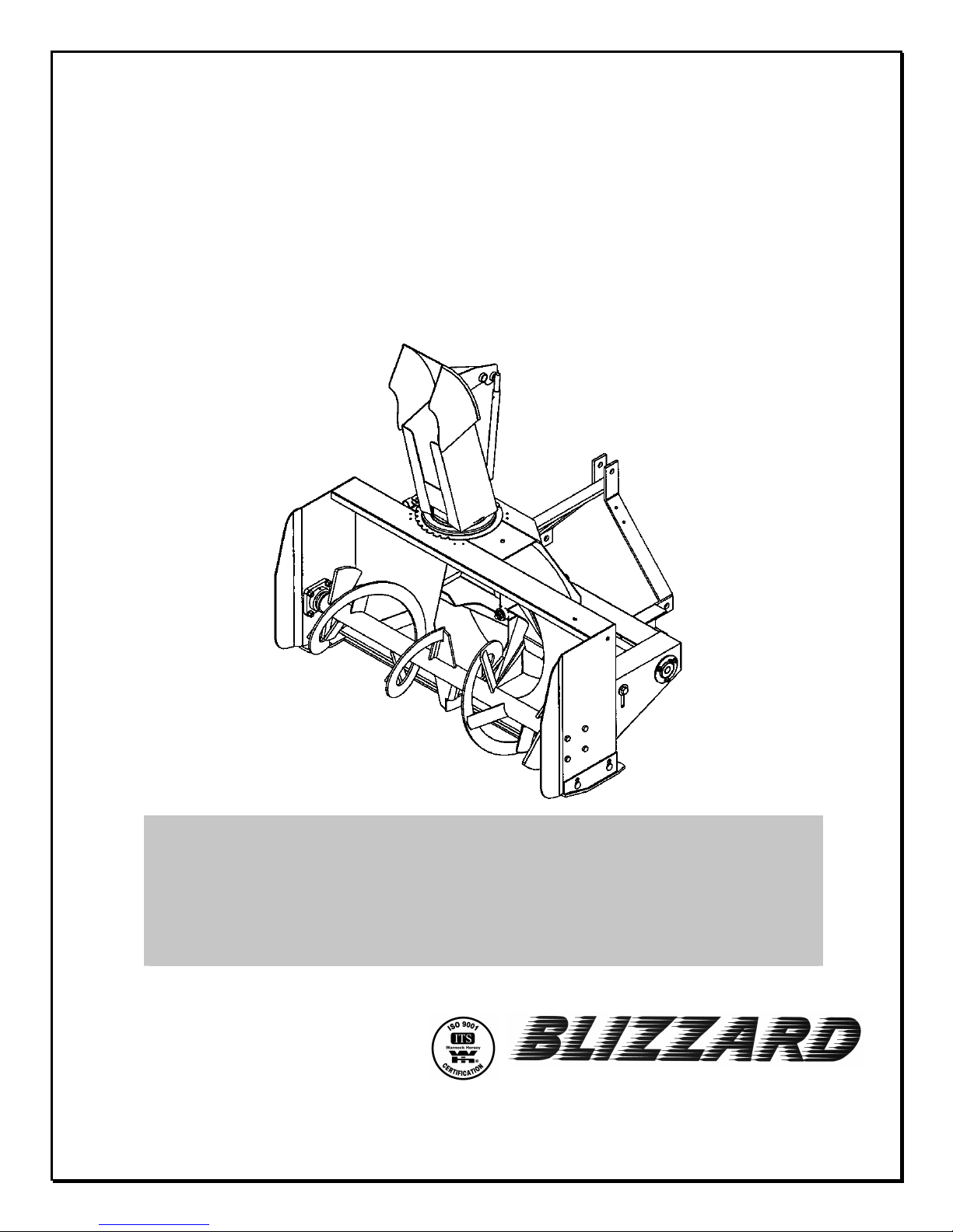
BLIZZARD B54 & B64 MODELS
OM 0277-A
06/02
SNOWBLOWER
SERIAL NO. 2024768 AND UP
by RAD Technologies Inc.
Page 2

Page 3

TABLE OF CONTENT
INTRODUCTION – TO THE PURCHASER.............................................................................................. 3
SAFETY PRE CAUTIONS.......................................................................................................................... 4
Before Operation.............................................................................................................................. 4
Notice................................................................................................................................................ 5
The Snowb l o wer............................................................................................................................... 5
Before Operation............................................................................................................... 5
Snowblower operati o n....................................................................................................... 6
The Tractor.......................................................................................................................................7
General Information........................................................................................................... 7
Operating the Trac to r......................................................................................................... 7
During Operatio n............................................................................................................... 7
Maintenance..................................................................................................................................... 8
Transporting...................................................................................................................................... 8
Storage ......................................................................................................................................... 8
DECALS ................................................................................................................................................... 9
ASSEMBLY.............................................................................................................................................. 10
Snowblo wer Assembly................................................................................................................... 10
Driveline Installation ...................................................................................................... 10
Chute & Manual Ro tati on............................................................................................... 10
Snowblower Installation................................................................................................. 12
Removing the S n owblowe r from th e Tra c to r................................................................. 12
Hydraulic Rotation with Cylinder – 8056 (Optional )....................................................... 13
OPERATION ........................................................................................................................................... 14
General Preparation ....................................................................................................................... 14
Operating Con tro l s ......................................................................................................................... 14
Work and Travel Speed ................................................................................................ 14
Raising and Lowerin g the Snowblower..........................................................................14
Drive Sha ft Oper a ti o n ................................................................................................... 14
Manual Rotation ............................................................................................................ 14
Reduction Chain Tension Adjustment ........................................................................... 14
Skid Shoe Adjustment ................................................................................................... 14
Manual Deflector Adjustment ........................................................................................ 14
Snow Remova l Methods ................................................................................................................ 15
OM 0277 – A 1
Page 4

TABLE OF CONTENT
MAINTENANCE ..................................................................................................................................... 16
Maintenance ..................................................................................................................................16
Storage .......................................................................................................................... 16
Driveline.......................................................................................................................... 16
Lubrication...................................................................................................................... 16
PARTS .................................................................................................................................................... 17
Introduction....................................................................................................................................... 17
Frame and Related Parts - Bli zzard B54 & B64 ............................................................................... 18
Gearbox (663485)............................................................................................................................. 20
Manual Rotation – K i t 9377...............................................................................................................21
Hydraulic Rotati on by Cylinder – Kit 8056.........................................................................................22
Driveline (665341).............................................................................................................................23
WARRANTY ........................................................................................................................................... 24
TORQUE SPECIFICATION TABLE ....................................................................................................... 25
OM 0277-A
2
Page 5

INTRODUCTION
TO THE PURCHASER
All BER-VAC and BLIZZARD products are
designed to give safe, dependable service if they
are operated and maintained according to
instructions. Read and understand this manual
before operation.
This manual has been prepared to assist the
owner and operators in the safe operation and
suitable maintenance of the implements. The
information was applicable to product s at the time
of manufacture and does not include
modifications made afterwards.
Read and understand this operator's manual
before attempting to put an implement into
service. Familiarize yourself with the operating
instructions and all the safety recommendations
contained in this manual and those labeled on the
implements and on the t ractor. Follow the safety
recommendations and make sure that those with
whom you work follow them.
To assist your dealer in handling your needs, please record hereafter the model number and serial
number of your implement and tractor. It is also advisable to supply them to your insurance company. It
will be helpful in the event that an implement or tractor is lost or stolen.
Illustrations
The illustrations may not necessarily reproduce
the full detail and the exact shape of the parts or
depict the actual models, but are intended for
reference only
Direction Reference
Right Hand and Left Hand are determined by
those seen by the conductor looking at the
machine while operating.
MODEL :
SERIAL NUMBER :
DATE OF PURCHASE :
OM 0277-A
3
Page 6

SAFETY PRECAUTIONS
SAFETY FIRST
This symbol, the industry's "Safet y Alert Symbol", is used t hroug hout t his manual and on labels
on the machine itself to warn of the possibility of personal injury. Read these instructions
carefully. It is essent ial that you read the instr uctions and saf et y regulat ions bef ore you attem pt
to assemble or use th i s u n i t.
DANGER : Indicates an immediately hazardous situation which, if not avoided, will
result in death or serious injury.
WARNING : Indicates a potentially hazardous situation which, if not avoided, could
result in death or serious injury.
CAU TION : Indicates a potentially hazardous situation which, if not avoided, may
result in minor or moderate injury.
IMPORTANT : Indicates that equipment or property damage could result if instructions
are not followed.
NOTE : Gives helpful information.
All products are designed to give safe, dependable service if they are operated and maintained
according to instructions. Read and understand this manual before operation
responsibility to be certain anyone operating this product reads this manual., and all other applicable
manuals, to become familiar with this eq uipment and all saf ety precautions. Failure to do so could result
in serious personal injury or equipment damage. If you have any questions, consult your dealer.
BEFORE OPERATION
Children
Tragic accidents can occur if t he operator is not
alert to the presence of children. Children are
generally attracted to machines and the work
being done. Never assume children will remain
where you last saw them.
1. Keep children out of the operating area and
under the watchful eye of another
responsible adult.
2. Be alert and turn machine off if children enter
the work area.
4. Never carry children while operating the
machine. They may f all off and be seriously
injured or interf ere with safe operation of the
machine.
5. Never allow children to play on the machine
or attachment even when turned off.
6. Never allow children to operate the machine
even under adult supervision.
7. Use extra care when approaching blind
corners, shrubs, trees, or other obstructions
that might hide children from sight.
. It is the owner's
3. Before and when backing, look behind and
look for small children.
OM 0277-A
4
Page 7

SAFETY PRECAUTIONS- continued
NOTICE
A safe operator is the best insurance against accidents. All oper ators, no mat ter how experienced they
may be, should read this Operator's Manual and all other relat ed manuals before attem pting to operate
an implement. Please read the following section and pay part icular attention to all safety recommendations contained in this manual and those labeled on the implements and on the tractor.
THE SNOWBLOWER
Before Operation
1. Read and understand this operator 's manual
and tractor operator's manual. Know how to
operate all controls and how to stop the unit
and disengage the controls quickly.
2. Never wear loose, torn, or bulky clothing
around the tractor and implement. It may
catch on moving parts or controls, leading to
the risk of accident.
3. Before the snow season, thoroughly inspect
the area where the equipment is t o be used
and remove all doormats, sleds, boards and
other foreign objects.
4. Disengage clut ch and shift into neutral bef or e
starting the engine.
5. Do not operate equipment in wintertime
without wearing adequate winter garments.
9. Replace all missing, illegible, or damaged
safety and warning decals. See list of
decals in the operator's manual.
10. Do not m odify or alter this equipment or any
of its components, or any equipment
function without first consulting your dealer.
11. Keep safety decals clean of dirt and grime.
6. Never attempt to make any adjustments
while engine is running. Read this manual
carefully to acquaint yourself with the
equipment as well as the tractor operator's
manual. Working with unfamiliar equipment
can lead to accidents. Be thoroug hly familiar
with the controls and proper use of the
equipment. Know how to stop the unit and
disengage the controls quickly.
7. Keep all shields in place and properly tighten
all mounting hardware.
8. Periodically, inspect all moving parts for
wear and replace with authorized service
parts if an excessive amount of wear is
present.
OM 0279-A
5
Page 8

SAFETY PRECAUTIONS- continued
Snowblower Operation
1. Before leaving the tractor unattended, take
all possible precautions. Disengage the
PTO, stop the engine and remove the
ignition key. Lower the implement to the
ground.
2. Before starting the snowblower, remove any
ice that has accumulated in the
auger/impeller.
3. Watch car efully for foreign objects that could
enter the blower while operating.
4. Be sure the clutch switch/lever is in OFF
position before starting engine.
5. Do not put hands or feet near rotation part s.
Keep clear of discharge opening at all times.
6. Exercise extreme caution when operating on
or crossing a gravel drive, walks, or roads.
Stay alert for hidden hazards or traffic. Do
not carry passengers.
14. Never operate machine at high transport
speeds on a slippery surface.
15. Use extra caution when backing up.
16. Do not direct discharge at bystanders or
animals. Ejected objects may cause injury.
17. Disengage power to auger/impeller when
transporting or when not in use.
18. Never operate the snowblower without good
visibility and lighting.
19. Prolonged exposure to loud noise can
cause impairment or loss of hear ing. Wear
a suitable hearing protective device such
as earmuffs or earplugs to protect against
objectionable or uncomfortable noises
7. Adjust collector housing height to clear
gravel or crushed rock surface.
8. Stop the engine, remove the k ey, and allow
the rotating parts t o stop before unclogging
the collector/impeller housing or chute, and
making any repairs, adjustments or
inspections. Use only a 36" long piece of
wood to unclog blower.
9. If the snowblower starts to vibrate
abnormally, stop the engine immediately
and check for cause. Excessive vibration is
generally a sign of trouble.
10. Do not run the engine indoors except when
starting engine and transport ing attachment
in or out of building. Carbon monoxide gas is
colorless, odorless and deadly.
11. Exercise extreme caution when changing
direction on slopes. Do not attempt to
operate on steep slopes.
12. Never operate snowblower without guards,
and other safety protective devices in place.
13. Never operate snowblower near glass
enclosures, automobiles, window wells,
embankments, etc., without proper
adjustment of snow discharge angle.
OM 0279-A
6
Page 9

SAFETY PRECAUTIONS- continued
THE TRACTOR
General Information
1. Read the operator's manual carefully before
using tractor. Lack of operating knowledge
can lead to accidents.
2. Do not perm it anyone but the oper ator t o ride
on the tractor. There is no safe place for
extra riders.
Operating the Tractor
1. Never run the tractor engine in a closed
building without adequate ventilation, as the
exhaust fumes are very dangerous.
2. Never allow an open flame near the fuel
tank or battery.
3. Make sure the shield is installed when
using a PTO-dr iven equipment and always
replace the shield if damaged.
4. Always bring the tractor to a complete stop,
shut off the engine, lower the implement to
the ground and remove the ignition key
before leaving the tractor.
5. Never park the tractor on a steep slope.
6. Do not attempt to operate on steep slopes.
7. Use of tire chains for better traction and
stability is recommended.
8. Always drive the tractor at speeds
compatible with safety, especially when
operating over rough ground, crossing
ditches, or when turning.
13. Never allow anyone to operate the
snowblower until they are thoroughly familiar
with basic tractor and snowblower operation.
14. Make sure the tractor is counterweight ed as
recommended by your dealer. Weights
provide the necessary balance to prevent
tip-over or loss of traction or steering.
15. Always make sure all snowblower
components are properly installed and
securely fastened BEFORE operation.
During Operation
1. Do not allow anyone to ride on the
tractor/snowblower at any time. There is no
safe place for passeng ers on this equipm ent.
The operator MUST sit in the tractor seat.
2. Eye and hearing prot ection is recommended
when operating the snowblower.
3. Operate only during daylight hours, or when
the area is well lit with bright artificial light.
4. Disengage the PTO (turn to “OFF”), place
the transmission in neutral, set the parking
brake, shut off the engine and remove the
key, and make sure rotating components
have stopped BEFORE leaving the
operator’s seat.
5. Inspect the snowblower after striking any
foreign object to assure that all snowblower
parts are safe and secure and not damaged.
9. Handle fuel with care, as it is highly
flammable.
10. Use approved fuel container.
11. Never add fuel to a running eng ine or a hot
engine.
12. Fill fuel tank outdoors with extreme care.
Never fill fuel tank indoor s. Replace fuel cap
securely and wipe up spilled fuel.
OM 0279-A
7
Page 10

SAFETY PRECAUTIONS- continued
MAINTENANCE
Park the tr act or /snowblower on level ground, set
the parking brak e, disengage the PTO, shut of f
the engine, remove the key, and lower the
implement to the ground BEFORE making any
snowblower adjustments.
1. To avoid injury, do not adjust, unclog or
service the snowblower with the tractor
engine running. Making sure rotating
components have completely stopped before
leaving the operator’s seat
2. Keep the tractor/snowblower clean. Snow
and ice build-up can lead to malfunction or
personal injury from thawing and refreezing
in garage.
3. Always wear eye protection when cleaning or
servicing the snowblower.
4. Do not work under any part of the tractor or
snowblower, unless it is securely supported
by safety stands.
5. Make sure all shields and guards are
securely in place following all service,
cleaning, or repair work.
6. Do not modify or alt er this equipment or any
of its components or operating functions. If
you have questions concerning
modifications, consult with your dealer.
TRANSPORTING
1. If the tractor/snowblower is to be driven on
public roads, it must be equipped with an
SMV (Slow Moving Vehicle) sign. Check
local traffic codes that may apply to unit
usage on public roads and highways in your
area.
2. Be alert for all other traffic when driving the
tractor/snowblower on public roads or
highways.
STORAGE
Before storing the snowblower, certain precautions should be taken to protect it from
deterioration.
1. Clean the snowblower thoroughly.
2. Make all the necessary repairs.
3. Replace all Safety Signs that are damaged,
lost, or otherwise become illegible. If a part
to be replaced has a sign on it, obtain a new
safety sign from your dealer and install it in
the same place as on the removed part.
4. Repaint all parts from which paint has worn
or peeled.
5. Lubricate the snowblower as instructed
under "Lubrication" section.
OM 0279-A
6. When t he snowblower is dry, oil all moving
parts. Apply oil liberally to all surfaces to
protect against rust.
7. Store in a dry place.
8
Page 11

DECALS
Replace immediately if damaged.
660988
660989
656779
664459
664458
664467
655834
Located on
driveline
Included with Option 8056
656780
OM 0279-A
664548
656781
9
Page 12

ASSEMBLY
2
SNOWBLOWER ASSEMBLY
The snowblower is assembled at the factory,
however, snowblower kit must be assembled.
Use the present manual and lay out all par ts for
assembly. Separate bolts and nuts into various
sizes. After assembly, torque all the bolts
according to the Torque Specification Table
enclosed at the end of the manual.
Driveline Installation
1. Remove paint from snowblower gearbox drive
shaft and grease driveline sliding surfaces
and yoke.
2. Remove the bolt of the yoke and slide
driveline yoke over drive shaft using sliding
action of the driveline. Make sure the driveline
is well secured to the drive shaft by replacing
the bolt and tightening it according to the
torque specification table.
Chute & Manual Rotation
1. Place the anti-friction ring (fig.2, item 4) over
the chute base, placing the raised part upside
and toward the center of the frame.
Figure
Figure 1
2. Insert the 1 11/16’’lg. plastic bushing (fig.4,
item 11) in the worm rotation bracket (fig.4,
item 6). G rease the two ends of the rotation
worm (fig.4, item 5) and insert the rotation
worm in the bushing (fig.4, item 11).
3. Insert the 1 5/16’’ plastic bushing (fig.4, item
10) in the tube welded behind blower (fig.3,
item 1)
4. Install the assembly by placing the worm
rotation bracket (f ig.4, item 6) under the right
upper plate of the snowblower (fig .3, item 2).
1
2
OM 0279-A
10
Figure 3
Page 13

ASSEMBLY
5. Install the adjustment tube (fig. 2, item 3) in
the lower hole on the backside of the chute
and the adjustment rod (fig. 2, item 2) in the
upper hole. Lock in place using the 1/4" x 2"
(fig. 2, item 7) cotter pins then insert the
∅5mm x 100mm hair pin (fig. 2, item 6) in the
adjustment tube hole (fig. 2, item 3)
6. Install the chute ( fig.2, item 1) over the plastic
insert (fig.2, item 4), applying grease in
between, and place the four retaining plates
(fig.2, item 5). Secure using eight 1/4’’ x 3/4’’
bolts, lockwashers and nuts (fig.2, items 8-9-
10). Tighten all bolts securely.
7. Install t he support ang le (fig 4, item 21) on the
3 point left attaching plat e using two 3/8’’NC x
1 1/4’’ bolts, lockwashers and nuts (fig. 4,
items 16-17-18). Tighten securely.
8. Install anchor tube (fig.4, item 15) on the
support angle (f ig .4 , item 21) using a 3/4’’NC x
1 1/2’’ bolt, lockwasher and nut (fig. 4, items
22-23-24) making sure the tube leans toward
the tractor.
9. Insert handle bracket (fig.4, item 14) inside
anchor tube (fig.4, item 15). Adjust the height
of the handle bracket according to your needs
and shorten it if necessar y. Fast en loosely with
a 3/8’’ x 5/16’’ set screw (fig 4, item 19).
10. Insert assembled rotation tube (fig.4, item 2)
inside the rotation worm. Align holes and
insert a 10-24 x 1’’ capscrew (fig.4, item 12)
making sure the capscrew sinks in the worm.
Secure with a nylon lock nut (fig. 4, item 13).
11. Install the plastic grommet (fig.4, item 20) in
the handle support.
12. Insert the handle (fig.4, item 1) inside the
grommet and inside the rotation tube (fig.4,
item 2) . Select desired length, align nearest
holes and secure with a 5mm x 100mm
hairpin (fig. 4, item 8).
13. Adjust handle position and height to a
comfortable and safe oper ating position after
the snowblower has been mounted to the
tractor. Tighten set screw (fig 4, item 19) on
anchor tube and the 3/4’’ x 1 1/2’’ bolt
securely (fig. 4, item 22).
Figure 4
OM 0279-A
11
Page 14

ASSEMBLY
CAUTION: To avoid personal injury,
check the full lifting range of the snow blow er,
to ensure that the chute rotation handle is
clear of the operator’s area when the
snowblower is in raised position.
14. Install plastic handle (fig.4 item 9) over
rotation handle.
15. Tighten all bolts according to the Torque
Specification Table at the end of the manual.
NOTE
DEFLECTOR, replace the adjustment rod and
tube with a 2" x 6" cylinder.
: To convert to a HYDRAULIC
Snowblower Installation
1. Attach tractor lower hitch arms (fig.5, items 1)
to snowblower attaching plates using the hitch
pins and secure with linchpins (fig.5, items 2).
2. Inst all the tractor upper hitch (f ig.5 item 3) on
the upper hole of snowblower (fig.5, item 5)
attaching plates using tractors pins and
linchpins (fig.5, items 4).
3. Adjust snowblower using the tractor upper
hitch so that it runs level.
CA UTION: Before connecting
snowblower driveline to tractor drive shaft,
make sure driveline is not too l ong in raised,
lowered and middle position. If the driveline
is too long it must be shortened, to avoid
damaged to tractor.
5. Connect driveline to tractor drive P.T.O.,
make sure that the driveline yoke pin is
properly engaged.
Removing Snowblower from Tractor:
1. Set snowblower completely on the ground to
release all pressure from the three- point. Set
parking brake and turn engine off.
2. Detach upper link by removing linchpin and
pin (fig.5, items 4).
3. Disconnect driveline from tractor P.T.O. shaft
and set driveline on support chain.
4. Carefully detach lower links (fig. 5, items 1)
by removing linchpins (fig.5, items 2) and
loosen anti-sway turnbuckles.
IMPORTANT
snowblower, retorque all bolts after the first
10 hours of operation.
: To avoid damage to the
4. Set the tractor anti-sway turnbuckles so the
snowblower does not sway.
Figure 5
OM 0279-A
12
Page 15

ASSEMBLY
6
Hydraulic Rotation with Cylinder 8056 (Optional) Figure 6
1. Place the plastic anti-fr iction insert (f ig.2, it em
4) over the chute base, placing the raised part
upside and toward the center of the frame.
2. Install the adjustment tube (fig. 2, item 3) in
the lower hole on the backside of the chute
and the adjustment rod (f ig. 2, item 2) in the
upper hole. Lock in place using the 1/4" x 2"
(fig. 2, item 7) cotter pins then insert the
∅5mm x 100mm hair pin (fig. 2, item 6) in the
adjustment tube hole (fig. 2, item 3)
3. Install the chute (fig .2, item 1) over the plastic
insert (fig.2, item 4), applying grease in
between, and place the four retaining plates
(fig.2, item 5). Secure using eight 1/4’’ x 3/4’’
bolts, lockwashers and nuts (fig.2, items 8-9-
10). Tighten all bolts securely.
4. Install the cylinder bracket (Fig. 6, item 1)
through the ∅13/32" hole on the frame by
inserting a 3/ 8" NC x 1" bolt (item 13), then
tighten with a flat washer (∅7/16" hole), a
lockwasher and a nut (items 6-7-8).
5. Install the bell crank (item 2) on the f rame by
sliding a spacer (item 4) under the cylinder
bracket, opposite the ∅11/16"hole. Insert a
bushing (item 5) in the ∅1 1/8" hole of the bell
crank and slide the bell crank between the f lat
bars of the cylinder bracket. Fasten
everything by inserting a 5/8" NC x 3 3/4" bolt
(item 12), a lockwasher and a nut (items 16-
17).
6. Install the push arm (item 3) by sliding it
between the bell crank plates, greasing
generously.
7. Insert a 3/8’’ x 3/4’’NC shoulder screw (item
14) under the part and tighten with a ∅3/8"
hole flat washer (item 10) and a 5/16’’NC
stover.nut (item 9), leaving some movement
to the push arm.
8. Slide the other push arm end between the flat
bars welded on the chute base. Inserting a
∅7/16" hole nylon flat washer (item 15) under
the push arm. Fasten everything with a 3/8" x
1" shoulder screw (item 11), a ∅3/8" hole
flatwasher (item 10) and a 5/16’’NC stover.nut
(item 9), leaving some movement to the
mechanism.
Figure
9. This system works with a 8’’ hydraulic cylinder
extension and a 20 1/4’’ centre-to-centre pin
retracted.
OM 0279-A
13
Page 16

OPERATION
GENERAL PREPARATION
1. Read the operator’s manual carefully before
using the tractor and snowblower. Be
thoroughly familiar with the controls and
proper use of the equipment. Know how to
stop the unit and disengage the controls
quickly.
2. Make sure the snowblower is clear of snow
before engaging the driveline.
3. Make sure the auger and fan operate freely.
4. Check the oil level in the worm gear box and
if necessary, add 80W90 SAE gear oil,
AGMA 5EP oil or equivalent.
5. Check the two shear bolts, one on the driving
shaft, and the one on the PTO, for proper
tightness.
6. Adjust so that the snowblower skid shoes run
level.
7. Wear adequate winter outer garments while
operating equipment.
OPERATING CONTROLS
Work and Travel Speed
Work ing ground speed will depend on the depth
and density of the snow to be cleared. Normally,
ground speed will range from 4 to 7 MPH for light,
dry snowfalls 3 to 6 inches, and 1 to 3 MPH for
heavy, wet or drifted snow. To transport,
disengage the drive shaft and raise the
snowblower to full transport height.
Reduction Chain Tension Adjustment
The premature wear of the chain may be caused
by tension being too tight. It is therefore important
not to tighten chain to its maximum.
• To adjust the tension on the drive chain,
loosen the bolt (item 1), securing the idler
sprocket to the snowblower housing.
• To tighten the chain, lower the bolt. Leave
approximately 1/8" deflection in one span of
the chain. Retighten securely the bolt holding
the idler sprocket.
Skid Shoe Adjustment
Adjust the skid shoes so that the snowblower
runs level and according to the surface conditions
so that stones are not thrown with the snow.
Adjust both skid shoes to the same height to
keep the cutting edge level and adjust upwards
for smooth surfaces.
Loosen skid shoe bolts (item 2) and adjust
according to instructions below, and securely
tighten bolts:
Clearance between cutting edge and surface:
Level paved surface : Adjust to 1/16" to 1/8"
•
Uneven or gravel surface: Adjust to 1/2" to 5/8"
•
Raising and Lowering the Snowblower
Move the three point lever on right hand side of
seat down or forward to lower, and up or
rearward to raise.
Drive Shaft Operation
The mid drive shaf t is activated by pulling up the
drive shaft lever on left side of seat. Push down
to disengage.
Ma n ua l R o t at i on (if so equipped)
Turning the handle clockwise turns the chute in
a clockwise direction.
WARNING: To avoid personal injury,
be sure the tractor engine is off, the drive
shaft disengaged, and all movement has
stopped before making any adjustments.
OM 0279-A
Manual Deflector Adjustment
Set the angle of deflection according to the
distance the snow must be thrown. To set the
deflector angle, remove the adjusting pipe hair
pin and adjust the adjusting rod to the desired
deflector angle. Secure with the adjusting pipe
hairpin.
14
Page 17

OPERATION
SNOW REMOVAL METHODS
When removing snow, do not use t he snowblower as a dozer blade to push snow. Let the snowblower
work its way through deep drifts. If the speed of your tractor is too f ast, the snowblower may become
overloaded and clog. For best r esults, r aise the snowblower and remove a top layer of snow. A second
pass with the snowblower will remove the remaining snow.
IMPORTANT
WARNING: Do not use hands or feet to unclog chute. Do not attempt to clear clogg ed chute of
snow while tractor engine is running. If t he chute clogs, disengage the drive shaft, shut off the tractor
engine, remove the ignition key, wait for all movement to stop, and then clear the snow from the chute.
A definite pattern of operation is required to thoroughly clean the snow area. These patterns will avoid
throwing snow in unwanted places as well as eliminating a second removal of snow
: Use full RPM power when removing wet, sticky snow. Low RPM power will tend to clog
the chute.
Where it is possible to throw the snow to the left
and right (above), as on a long driveway, it is
advantageous to start in the middle. Plow from
one end to the other, throwing snow to both sides
without changing the direction of the discharge
guide
OM 0279-A
If the snow can only be thrown to one side of the
driveway or sidewalk (above), start on the
opposite side. At the end of t he first pass, rot ate
the discharge guide 180 degrees for the return
pass. At the end of each succeeding pass, rot ate
the discharge guide 180 degrees to maintain
direction of throw in the same area.
15
Page 18

MAINTENANCE
MAINTENANCE
Storage
1. Check the shear bolts at f req uent intervals f or
proper tightness to be sure the blower is in
safe working condition.
2. Never store the tractor with fuel in the fuel
tank inside a building where open flame or
sparks are present. Allow the engine to cool
before storing in any enclosure.
3. Run the snowblower a few minutes after
blowing snow to prevent freeze up of the
auger and the impeller.
WARNING: Provide adequate blocking
before working under the snowblower when in the
raised position.
Driveline
Lubrication
1. GEAR : Check the oil level in the worm gear
drive every month. If necessary add SAE
80W90 gear oil, AGMA 5EP or equivalent.
2. REDUCTION CHAIN : Lubricate with chain
saw lubricant every 4 hours of operation and
after each use.
3. DRIVELINE (S) : Grease each u-joint fitting
every 8 hours of operation. Slide drive shaft
apart and coat sliding surfaces with grease
every 8 hours of operation.
4. ROTATION SHAFT : Grease the shaft each 8
hours of operation.
IMPORTANT: When the snowblower is not
used for more than two weeks, perform
driveline maintenance and alw ays store it in a
dry place, away from bad weather conditions.
OM 0279-A
16
Page 19

PARTS
I
NTRODUCTION
All parts are illust rated in "exploded views" which show the individual parts in their norma l relationship
to each other. Reference numbers are used in t he illustrations. These numbers correspond to those in
the "Reference Number" (REF) colum n, and are followed by the description and quantity required.
O/L - "Obt ain Locally" in the par t number colum n indicates common hardware that is available at your
local hardware supply.
All reference to right and lef t, forward or rearward, are from the operator's seat, facing the steering
wheel.
Orders must give the complete description, correct part number, the t otal amount required, t he serial
number, the method of shipment and the shipping address.
The manufacturer reserves the rights to change, modify, or elim inate from time to time, for technical
or other reasons, cer tain or all data, specifications, or the product or pr oducts themselves, without any
liability or obligation.
OM 0277-A
17
Page 20

PARTS
FRAME AND RELATED PARTS – BLIZZARD B54 & B64
OM 0277-A 18
Page 21

PARTS
Cotter p
airp
∅
5
g
FRAME AND RELATED PARTS – BLIZZARD B54 & B64
REF. DESCRIPTION QTY. PART #
B54 B64
1 Housing 1 --- --2 Chute ass'y 1 664793 664793
3 Nylon ring 1 659151 659151
4 Bolt hex. 1/4" NC x 3/4" 8 O/L O/L
5 Retaining plate 4 659146 659146
6 Lockwasher 1/4" dia. hole 8 O/L O/L
7 Nut hex. 1/4 " NC 8 O/L O/L
8
9 Bearing 1 1/4" hole 2 4300001 4300001
10 Bolt hex. 1/2"NC x 1 1/2" 8 O/L O/L
11 Lockwasher 1/2" 12 O/L O/L
12 Nut hex. 1/2" NC 12 O/L O/L
13 Auger 1 666259 666269
14 Fan 1 664400 664400
15 Key 3/8" x 3/8" x 2 3/4" lg 1 654174 654174
16 Bolt hex. 3/8"NC x 1 1/2" 5 O/L O/L
17 Lockwasher 3/8" dia. hole 5 O/L O/L
18 Flatwasher 7/16" dia. hole 1 O/L O/L
19 Idler bushing 1 666264 666264
20 Idler 1 654010 654010
21 Flatwasher 11/16" dia. hole 2 O/L O/L
22 Bolt hex. 5/8"NC x 4 1/2" 1 O/L O/L
23 Idler 1 666263 666263
24 Chain #60 x 72 links, incl. connect. link 1 659143 659143
25 Fan washer 1 661554 661554
26 Adjustment tube 1 654076 654076
27 Adjustment rod 1 654074 654074
28
H
29 Driveline series 40 1 665341 665341
30 Hitch pin Cat.1 2 654196 654196
31 Bearing 1 1/8" hole with locking collar 1 4300016 4300016
32 Lockwasher 5/8" 1 O/L O/L
33 Nut hex. 5/8"NC 1 O/L O/L
34 Connecting link #60 1 654839 654839
35 Driving shaft 1 666256 666268
36 Shear plate 1 666257 666257
37 Bolt hex. 5/16"NC x 1 3/4" gr.5, incl. nut 1 665547 665547
38 Gearbox 1 663485 663485
39 Nut hex. 3/8"NC 8 O/L O/L
40 Bolt hex. 3/8"NC x 5" 4 O/L O/L
41 Linchpin 7/16" PTD 2 O/L O/L
42 Left adjustable skid shoe 1 666254 666254
43 Right adjustable skid shoe 1 666255 666255
44 Carriage bolt 1/2" NC x 1" lg 4 O/L O/L
45 Carriage bolt 3/8" x 3/4" lg 3 O/L O/L
46 Serrated flange nut 3/8" NC 3 O/L O/L
47 Sprocket #60A32 1 654167 654167
48 Self-lubricating bushing 1 659834 659834
49 Flange with grease slot 1 4300014 4300014
50 Flange with tip and grease fittin
in ∅1/4" x 2"
in
mm x 100mm lg.
2 O/L O/L
1 O/L O/L
1 4300015 4300015
OM 0277-A 19
Page 22

PARTS
G
EARBOX (663485)
REF. DESCRIPTION QTY. PART #
1 Casing 2 659848
2 Gear 2 662236
3 Shim 1 656649
4 Bearing 4 656653
5 Parallel Key 2 659850
6 Input Shaft 1 664663
7 Oil Seal 3 659852
8 Output Shaft 1 659853
9 Shim 1 659854
10 Snap Ring 2 656652
11 Shim 2 659855
12 O-Ring 1 661144
13 Plug 1 659847
14 Bolt hex. M8 x 55mm – 8.8 8 O/L
15 Nut hex. M8, -8 8 O/L
OM 0277-A
20
Page 23

PARTS
MANUAL ROTATION – KIT 9377
REF. DESCRIPTION QTY PART #
1 Handle 1 658252
2 Rotation tube 1 660188
3 Rotation yoke 1 659595
4 Universal block 1 658193
5 Rotation worm 1 659161
6 Worm r otation bracket 1 659145
7 Roll pin 1/4" x 1 1/4" 1 O/L
8 Hairpin 5mm x 100mm 1 659073
9 Plastic handle 1 656797
10 Plastic bushing 1 5/16" 1 657335
11 Plastic bushing 1 11/16" 1 657336
12 Capscrew 10-24 x 1" 1 O/L
13 Nylon insert locknut 10-24 1 O/L
14 Handle support bracket 1 660187
15 Anchor tube 1 660269
16 Bolt hex. 3/8"NC x 1 1/4" 2 O/L
17 Nut hex. 3/8" 2 O/L
18 Lockwasher 2 O/L
19 Square head setscrew 3/8" x 5/16" 1 O/L
20 Plastic grommet 1 657390
21 Support angle 1 660388
22 Bolt hex. 3/4"NC x 1 1/2" 1 O/L
23 Lockwasher 1 O/L
24 Nut hex. 3/4" 1 O/L
OM 0277-A 21
Page 24

PARTS
HYDRAULIC ROTATION BY CYLINDER – KIT 8056
EF. DESCRIPTION QTY PART NUMBER
R
1 Cylinder Bracket 1 664450
2 Bell Crank 1 664451
3 Push Arm 1 664452
4 Spacer 1 664429
5 Bushing 1 664428
6 Flatwasher (7/16") 1 O/L
7 Hex. Nut (3/8" NC) 1 O/L
8 Lockwasher (3/8") 1 O/L
9 Stover Nut (5/16" NC) 2 O/L
10 Flat washer (3/8") 2 O/L
11 Shoulder Screw (3/8" x 1", 5/16" NC) 1 664583
12 Hex. Bolt (5/8" NC x 3 3/4") 1 O/L
13 Hex. Bol t (3 /8 " NC x 1") 1 O/L
14 Shoulder screw (3/8" NC x 3/4", 5/16"NC) 1 664576
15 Nylon Flat washer (7/16") 1 O/L
16 Lockwasher (5/8") 1 O/L
17 Hex. nut (5/8" NC) 1 O/L
OM 0277-A 22
Page 25

PARTS
DRIVELINE (665341)
REF. DESCRIPTION QTY. PART NUMBER
1 Quick disconnect Yoke - Q.L. type 1 664543
2 Universal Joint Kit 2 658094
3 Outer Yoke 1 664544
4 Outer Tube 1 659107
5 Inner Tube 1 659105
6 Inner Yoke 1 664545
7 Yoke with Key 1 665350
8 Shield 1 664547
9 Bolt 8mm x 1.25mm x 45mm long gr.8.8 1 O/L
10 Nut 8mm x 1.0mm 1 O/L
OM 0277-A 23
Page 26

WARRANTY
RAD TECHNOLOGIES INC.
RAD TECHNOLOGIES INC. warrants to the original buyer that the equipment is f ree from defects in
material and workmanship. RAD TECHNOLOGIES INC.'s obligation, under this warranty, will be
limited to the repair or replacement of any non-wear part or component, which RAD TECHNOLOGIES
INC. finds to be defective within one year from the date of original purchase (unless otherwise-
specified). The applicable warranty period for comm ercial or rental use shall be ninety (90) days from
the date of purchase
In no event shall RAD TECHNOLOGIES INC. be liable f or consequential, special, direct or indirect
damages incurred by the buyer/user.
All components not manufactured by RAD TECHNOLOGIES INC. (such as motors, actuators,
hydraulic components, tires, ...etc.) are covered by the original manufacturer's warranty in conjunction
with RAD TECHNOLOGIES INC.
RAD's obligation under t his warranty shall be limited to repairing or replacing, free of charge to t he
original purchaser, any part that , in RAD' s judg ment , shall show evidence of such def ect, provided the
distributor returns the part prepaid within thirty (30) days from date of failure.
This warranty shall not be interpreted to render RAD TECHNOLOGIES INC. liable for injuries or
damages of any kind or nature to person or property. This warranty does not extend to losses
because of delays, or to any expenses or losses incurred for labor, subst itute machinery, rental or for
any other reason.
Except as set forth above, RAD TECHNOLOGIES INC. shall have no obligation or liability of any kind
on account of any of its equipment and shall not be liable f or special or consequential damages. RAD
TECHNOLOGIES INC. makes no other warranty, expressed or implied, and specifically, RAD
TECHNOLOGIES INC. disclaims any implied warranty or merchantability or fitness for a particular
purpose. Some states or provinces do not permit limitations or exclusions of implied
warranties or incidental or consequential damages, so the limitations or exclusions in this
warranty may not apply.
This warranty is subject to any existing conditions of supply, which may directly affect our ability to
obtain materials or manufacture replacement parts. RAD TECHNOLOGIES INC. reserves the right to
make improvements in design or changes in specifications at any time, without incurring any
obligation to owners of units previously sold.
No one is authorized to alter, modify or enlarge this warranty nor the exclusions, limitations and
reservations.
2835 Chemin de l'Aéroport, Thetford Mines (Québec) G6G 5R7
Tél.: (418) 338-4499 Fax: (418) 388-6090
Internet: www.radinte r.c o m EM AIL: radtech@radinter.com
OM 0277-A
24
Page 27

TORQUE SPECIFICATION TABLE
GENERAL SPECIFICATION TABLE
Use the following torques when special torques are not given Note: These values apply to
fasteners as received from supplier, when dry. These values do not apply if lubricants are used.
BOLT SIZES (SAE)
INCHES Pounds-Foot Newtons-Meter
1/4 5 7
5/16 10 14
3/8 20 27
7/16 25 41
1/2 88 119
9/16 121 164
5/8 165 224
3/4 297 403
7/8 440 597
1 638 865
1 1/8 840 1139
1 1/4 1180 1600
1 3/8 1570 2129
TORQUE
1 1/2 2070 2807
BOLT SIZES (METRIC)
MILLIMETERS
M6 10 13
M8 22 30
M10 40 54
M12 59 80
M14 93 126
M16 130 176
M18 168 228
M20 205 278
TORQUE
Pounds-Foot Newtons-Meter
OM 0277-A
25
Page 28

Manufactured by:
RAD Technologies Inc.
2835, Chemin de l’Aéroport
Thetford Mines, Québec, Canada, G6G 5R7
Tel.: (418) 338-4499 - Fax.: (418) 338-6090
E-mail : radtech@radinter.com
Internet : www.radinter.com
Printed in Canada
 Loading...