

Page 1
Blizzard, PO Box 245038, Milwaukee, WI 53224-9538 • www.blizzardplows.com
January 1, 2012
Lit. No. 41606, Rev. 01
69982
UNDERCARRIAGE KIT
GM K2500/2500HD/3500/3600 Silv/Sierra 2011 - __
GM C3500/3600 Silv/Sierra 2011 - __
Installation Instructions
CAUTION
Read this document before installing the
snowplow.
CAUTION
See your BLIZZARD® outlet/Web site for
specifi c vehicle application recommendations
before installation. The Undercarriage
Selection Guide has specifi c vehicle and
snowplow requirements.
A DIVISION OF DOUGLAS DYNAMICS, L.L.C.
Page 2
SAFETY
SAFETY DEFINITIONS
WARNING
Indicates a potentially hazardous situation
that, if not avoided, could result in death or
serious personal injury.
CAUTION
Indicates a potentially hazardous situation
that, if not avoided, may result in minor or
moderate injury. It may also be used to alert
against unsafe practices.
NOTE: Indicates a situation or action that can lead
to damage to your snowplow and vehicle or other
property. Other useful information can also be
described.
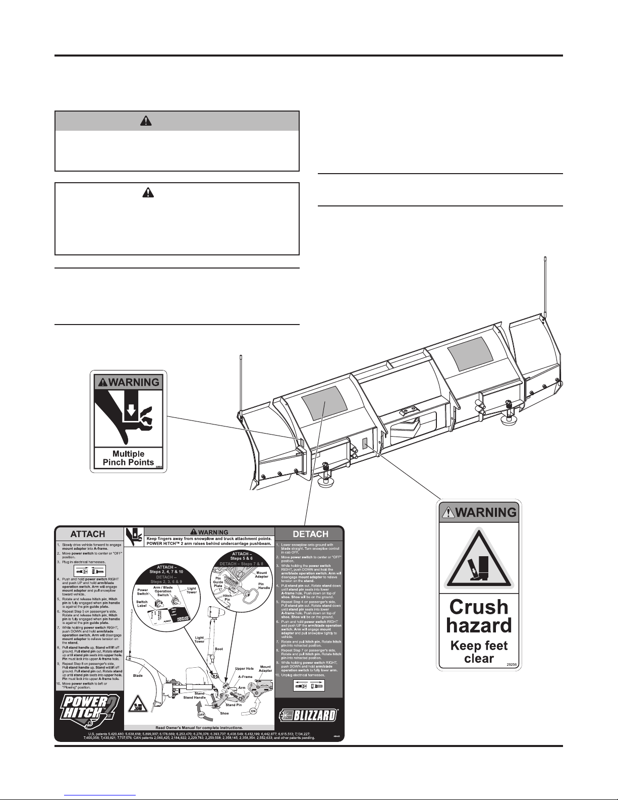
WARNING/CAUTION & INSTRUCTION
LABELS
Become familiar with and inform users about the
warning and instruction labels on the back of the
blade.
NOTE: If labels are missing or cannot be read, see
your sales outlet.
POWER PLOW™ &
SPEEDWING™ Blades Only
(both sides)
Lit. No. 41606, Rev. 01 2 January 1, 2012
Page 3

SAFETY
SAFETY PRECAUTIONS
Improper installation and operation could cause
personal injury and/or equipment and property damage.
Read and understand labels and the Owner's Manual
before installing, operating or making adjustments.
WARNING
Lower the blade when the vehicle is parked.
Temperature changes could change
hydraulic pressure, causing the blade to
drop unexpectedly or damaging hydraulic
components. Failure to do this could result in
serious personal injury.
WARNING
The driver shall keep bystanders clear of the
blade when it is being raised, lowered or angled.
Do not stand between the vehicle and the blade
or within 8 feet of a moving blade. A moving or
falling blade could cause personal injury.
WARNING
Keep hands and feet clear of the blade and
A-frame when mounting or removing the
snowplow. Moving or falling assemblies could
cause personal injury.
WARNING
Do not exceed GVWR or GAWR including the
blade and ballast. The rating label is found on
the driver-side vehicle door cornerpost.
WARNING
To prevent accidental movement of the blade,
always turn the control OFF whenever the
snowplow is not in use. The power indicator
light will turn OFF.
PERSONAL SAFETY
• Remove the ignition key and put the vehicle in
park or in gear to prevent others from starting the
vehicle during installation or service.
• Wear only snug-fi tting clothing while working on
your vehicle or snowplow.
• Do not wear jewelry or a necktie, and secure long
hair.
• Wear safety goggles to protect your eyes from
battery acid, gasoline, dirt and dust.
• Avoid touching hot surfaces such as the engine,
radiator, hoses and exhaust pipes.
• Always have a fi re extinguisher rated BC handy,
for fl ammable liquids and electrical fi res.
FIRE AND EXPLOSION
WARNING
Gasoline is highly fl ammable and gasoline
vapor is explosive. Never smoke while
working on vehicle. Keep all open fl ames
away from gasoline tank and lines. Wipe up
any spilled gasoline immediately.
Be careful when using gasoline. Do not use gasoline
to clean parts. Store only in approved containers away
from sources of heat or fl ame.
CELL PHONES
A driver's fi rst responsibility is the safe operation of
the vehicle. The most important thing you can do
to prevent a crash is to avoid distractions and pay
attention to the road. Wait until it is safe to operate
Mobile Communication Equipment such as cell phones,
text messaging devices, pagers or two-way radios.
VENTILATION
WARNING
Remove blade assembly before placing
vehicle on hoist.
CAUTION
Refer to the Undercarriage Selection Guide
for minimum vehicle recommendations and
ballast requirements.
Lit. No. 41606, Rev. 01 3 January 1, 2012
WARNING
Vehicle exhaust contains lethal fumes.
Breathing these fumes, even in low
concentrations, can cause death. Never
operate a vehicle in an enclosed area without
venting exhaust to the outside.
Page 4

TORQUE CHART
NOISE
Airborne noise emission during use is below 70 dB(A)
for the snowplow operator.
VIBRATION
Operating snowplow vibration does not exceed
2.5 m/s2 to the hand-arm or 0.5 m/s2 to the whole body.
TORQUE CHART
CAUTION
Read instructions before assembling.
Fasteners should be fi nger tight until
instructed to tighten according to the torque
chart. Use standard methods and practices
when attaching snowplow including proper
personal protective safety equipment.
Recommended Fastener Torque
Chart (ft-lb)
Size
1/4-20 6 9 13
5/16-18 11 18 28
3/8-16 19 31 46
3/8-24 24 46 68
7/16 -14 30 5 0 75
1/2-13 45 75 115
9/16-12 66 110 165
5/8-11 93 150 225
3/4-10 150 250 370
7/8 -9 150 378 591
1-8 220 583 893
SAE
Grade 2
Metric Grade 8.8 (ft-lb)
Size Torque Size Torque
M 6 7 M 12 60
M 8 17 M 14 95
M 10 35 M 16 155
These torque values apply to fasteners
except those noted in the instruction.
Tor que
Grade 5
SAE
Grade 8
SAE
Lit. No. 41606, Rev. 01 4 January 1, 2012
Page 5

UNDERCARRIAGE INSTALLATION
INSTALLATION INSTRUCTIONS
NOTE: For easier assembly and installation,
vehicle and all snowplow components should
be on a smooth, level, hard surface, such as
concrete.
1. Remove the tow hooks. Notch the lower plastic
portion of the bumper to fi t, as shown below.
Notch bumper as shown
4. Insert a 1/2" x 1-3/4" cap screw and washer
through the rectangular opening in the inner
surface of the frame, through the frame and the
rear bracket. Secure loosely with a 1/2" locknut.
Adjust the position of the rear brackets upwards as
far as possible and secure the 1-3/4" fastener, as
well as the three 1-1/4" cap screws from Step 3.
1/2" x 1-3/4" Cap Screw
and Washer
Rectangular
opening in the
inner frame.
2. Beginning with the passenger-side mount, align
the forward mount holes with tow hook holes in
frame. Reinstall the tow hook and fasteners and
tighten according to the torque charts provided.
Repeat on the opposite side.
3. Position the rear brackets around the front
stabilizer bar as shown in the photo below.
Loosely attach the rear brackets to the mounts
using three 1/2" x 1-1/4" cap screws and locknuts
on each mount.
Rear
Bracket
Stabilizer
Bar
CAUTION
Use caution not to pinch, cut or drill through
any wires or hoses running along the frame rail.
5. On the passenger's side, drill two 17/32" diameter
holes through the vehicle frame using the
rearmost 9/16" holes in the brackets as guides.
Drill 17/32" dia. holes
through the frame.
Rectangular
Opening
1/2" x 1-1/4"
Cap Screw
Lit. No. 41606, Rev. 01 5 January 1, 2012
Page 6

UNDERCARRIAGE INSTALLATION
Insert two cap screws with handles and washers
through the rectangular opening in the rear
bracket and through the previously drilled holes in
the vehicle frame. Secure with 1/2" locknuts. Bend
or cut the handles so that they do not interfere
with the range of motion of the front stabilizer bar.
Bend or cut
handles after
securing with
1/2" locknuts.
Repeat this process on the driver's side, noting
that the rearmost cap screw on handle must be
inserted through the round hole behind the rear
bracket as shown. Bend or cut the handles so that
they do not interfere with the range of motion of
the front stabilizer bar.
CAUTION
Use caution not to pinch, cut or drill through
any wires or hoses running along the frame rail.
6. Using the 7/16" hole on the front of the mounts as
a guide, drill a 13/32" diameter hole through the
frame rail. Insert a 3/8" x 1" cap screw through
the drilled hole and secure with a 3/8" locknut and
washer.
Drill 13/32" dia. hole
through the frame rail.
Bumper not shown.
7. Use the off-truck portion of the snowplow to
determine any additional trimming of the lower
bumper valence required to clear all snowplow
components when attaching/detaching the
snowplow from the vehicle.
On some truck models, there may be a slight
interference between the hook on the stand
assembly and the vehicle's tow hooks. In these
instances, removal of the tow hooks may be
required for smooth snowplow attach/detach
operation. If the tow hooks must be removed, use
the provided 1/2" x 1-3/4" cap screws, washers
Insert rearmost
cap screw on handle
through hole behind
the rear bracket.
Lit. No. 41606, Rev. 01 6 January 1, 2012
and locknuts in place of the tow hooks and
fasteners to secure the mounts to the front of the
vehicle frame. Washers should be placed on the
inside surfaces of the frame.
Page 7

MOUNT ADAPTER INSTALLATION
ELECTRICAL INSTALLATION
If the vehicle is equipped with fused battery studs, the
plow battery cables should not be attached to the
fused side (see below).
MOUNT ADAPTER MEASUREMENT
With the vehicle on level ground, measure from the
ground to the center of the hole on the U-bracket side
plate of the mount.
MOUNT ADAPTER INSTALLATION
If adapter plates are required, install as follows:
1. Position an adapter plate against the driver's side
portion of the mount adapter as shown. Insert a
3/4" x 2-3/4" cap screw through the lower front
adapter plate hole and through the appropriate
hole on the mount adapter. Secure with a locknut.
Mount Adapter
3/4" Washer
Adapter
Plate
3/4" Locknut
3/4" x 2-3/4" Cap Screw
2. Insert a cap screw through the rear adapter plate
hole, through the slot on the mount adapter and
through a washer. Secure with a locknut.
The height of the mount should be 14-1/4" or less from
the center of the U-bracket hole to level ground. If the
measured height is 14-1/4" or less, no mount adapter
height adjustment is required.
If the measured height is 14-1/4" to 16", install the
short height adjustment adapter plates to the mount
adapter as described. (The mount adapter comes
packaged with the blade crate assembly.)
Adapter
Plate
Mount
Adapter
Center
of Hole
14-1/4" to 16"
Mount
3. Repeat for the passenger's side. Tighten all
fasteners according to the torque chart.
When positioning the mount adapter between the
undercarriage brackets, insert a spacer between
the adapter plate and the inner side plate of the
undercarriage as shown.
Spacer
Hairpin
Cotter
Adapter
Washer
NOTE: After fi ve to ten hours of snowplow usage,
retorque all undercarriage assembly fasteners.
Plate
Clevis Pin
Lit. No. 41606, Rev. 01 7 January 1, 2012
Page 8

Blizzard
PO Box 245038
Milwaukee, WI 53224-9538
www.blizzardplows.com
A DIVISION OF DOUGLAS DYNAMICS, L.L.C.
Blizzard reserves the right under its product improvement policy to change construction or design details and furnish equipment when so
altered without reference to illustrations or specifi cations used. Blizzard or the vehicle manufacturer may require or recommend optional
equipment for snow removal. Do not exceed vehicle ratings with a snowplow. Blizzard offers a limited warranty for all snowplows and
accessories. See separately printed page for this important information. The following are registered (®) or unregistered (™) trademarks of
Douglas Dynamics, L.L.C.: BLIZZARD®, POWER HITCH™ 2, POWER PLOW™, SPEEDWING™.
Lit. No. 41606, Rev. 01 8 January 1, 2012
Printed in U.S.A.
 Loading...