

Page 1
Blizzard, PO Box 245038, Milwaukee, WI 53224-9538 • www.blizzardplows.com
March 15, 2010
Lit. No. 69656, Rev. 03
30269
UNDERCARRIAGE KIT
Ford Super Duty F-250/350/450/550 2008 - 10
Installation Instructions
CAUTION
Read this document before installing the
snowplow.
CAUTION
See your BLIZZARD® outlet/Web site for
specifi c vehicle application recommendations
before installation. The Undercarriage
Selection Guide has specifi c vehicle and
snowplow requirements.
A DIVISION OF DOUGLAS DYNAMICS, L.L.C.
Page 2
SAFETY
SAFETY DEFINITIONS
WARNING
Indicates a potentially hazardous situation
that, if not avoided, could result in death or
serious personal injury.
CAUTION
Indicates a potentially hazardous situation
that, if not avoided, may result in minor or
moderate injury. It may also be used to alert
against unsafe practices.
NOTE: Indicates a situation or action that can lead
to damage to your snowplow and vehicle or other
property. Other useful information can also be
described.
WARNING/CAUTION & INSTRUCTION
LABELS
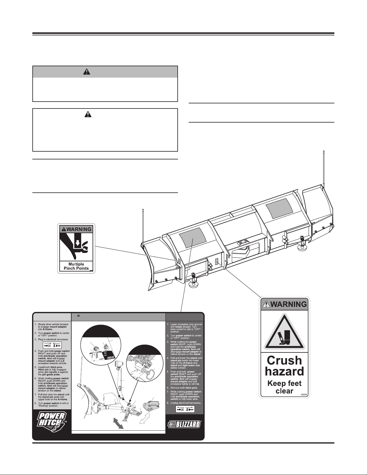
Become familiar with and inform users about the
warning and instruction labels on the back of the
blade.
NOTE: If labels are missing or cannot be read, see
your sales outlet.
POWER PLOW® and
SPEEDWING™ Blades Only
(both sides)
ATTACH DETACH
U.S. Patents 5,42 0,480; 5,638,618; 5 ,899,007; 6,178,669; 6, 253,470; 6,276,076; 6,393,737; 6,408,549; 6,412,199; 6,442,877; 6,615,513; 7,134,227; RE 35,70 0;
Lit. No. 69656, Rev. 03 2 March 15, 2010
WARNING: Ke ep fingers awa y from snowplow an d truck attac hment
points . POWER HITCH™ arm ra ises behind und ercarriag e pushbeam.
ATTAC H –
Steps 2, 4 , 6 & 8
DETACH –
Steps 2, 3, 5 & 7
Arm / Blade
Power
Operation
Switch
Switch
Label
Blade
Read Owner's Manual for Complete Instructions.
CAN Patents 2,060,425; 2,184,922; 2,229,783; 2,259,508; 2,358,145; 2,358,354; 2,466,195; and other patents pending.
Switch
Light
Towe r
Stand
ATTAC H –
Step 5
DETACH – Step 6
Mount
Pin
Guide
Plate
Hitch
Pin
Light
Towe r
Boot
Raise
OFF
OFF
Lower
Plowing
Operation
Arm/Blade
ARM/BLADE
POWER
48207
OPERATION
A-Frame
Pin
Upper
Hole
Stand
Adapter
Pin
Handle
Mount
Adapter
Arm
48208
Page 3

SAFETY
SAFETY PRECAUTIONS
Improper installation and operation could cause
personal injury and/or equipment and property damage.
Read and understand labels and the Owner's Manual
before installing, operating or making adjustments.
WARNING
Lower blade when vehicle is parked.
Temperature changes could change
hydraulic pressure, causing the blade to
drop unexpectedly or damaging hydraulic
components. Failure to do this could result in
serious personal injury.
WARNING
The driver shall keep bystanders clear of the
blade when it is being raised, lowered or angled.
Do not stand between the vehicle and the blade
or within 8 feet of a moving blade. A moving or
falling blade could cause personal injury.
WARNING
Keep hands and feet clear of the blade and
A-frame when mounting or removing the
snowplow. Moving or falling assemblies could
cause personal injury.
WARNING
Do not exceed GVWR or GAWR including the
blade and ballast. The rating label is found on
the driver-side vehicle door cornerpost.
WARNING
To prevent accidental movement of the
blade, always turn the ON/OFF switch to OFF
whenever the snowplow is not in use. The
control indicator light will turn off.
PERSONAL SAFETY
• Remove ignition key and put the vehicle in park or
in gear to prevent others from starting the vehicle
during installation or service.
• Wear only snug-fi tting clothing while working on
your vehicle or snowplow.
• Do not wear jewelry or a necktie, and secure long
hair.
• Wear safety goggles to protect your eyes from
battery acid, gasoline, dirt and dust.
• Avoid touching hot surfaces such as the engine,
radiator, hoses and exhaust pipes.
• Always have a fi re extinguisher rated BC handy,
for fl ammable liquids and electrical fi res.
FIRE AND EXPLOSION
WARNING
Gasoline is highly fl ammable and gasoline
vapor is explosive. Never smoke while
working on vehicle. Keep all open fl ames
away from gasoline tank and lines. Wipe up
any spilled gasoline immediately.
Be careful when using gasoline. Do not use gasoline
to clean parts. Store only in approved containers away
from sources of heat or fl ame.
CELL PHONES
A driver's fi rst responsibility is the safe operation of
the vehicle. The most important thing you can do
to prevent a crash is to avoid distractions and pay
attention to the road. Wait until it is safe to operate
Mobile Communication Equipment such as cell
phones or two-way radios.
VENTILATION
WARNING
Remove blade assembly before placing
vehicle on hoist.
CAUTION
Refer to the Undercarriage Selection Guide
for minimum vehicle recommendations and
ballast requirements.
Lit. No. 69656, Rev. 03 3 March 15, 2010
Vehicle exhaust contains lethal fumes.
Breathing these fumes, even in low
concentrations, can cause death. Never
operate a vehicle in an enclosed area without
venting exhaust to the outside.
WARNING
Page 4

TORQUE SPECIFICATIONS
TORQUE CHART
CAUTION
Read instructions before assembling.
Fasteners should be fi nger tight until
instructed to tighten according to the torque
chart. Use standard methods and practices
when attaching snowplow including proper
personal protective safety equipment.
Grade Identifi cation for J429–Grade 5 Bolt Grade Identifi cation for J429–Grade 8 Bolt
SAE J429 Grade 5 Torque Values SAE J429 Grade 8 Torque Values
Nominal
Thread Size
1/4-20 2,000 6 ft-lb 8 ft-lb 1/4-20 2,850 9 ft-lb 12 ft-lb
5/16-18 3,350 13 ft-lb 18 ft-lb 5/16-18 4,700 18 ft-lb 25 ft-lb
3/8-16 4,950 23 ft-lb 31 ft-lb 3/8-16 6,950 32 ft-lb 44 ft-lb
7/16-14 6,800 37 ft-lb 50 ft-lb 7/16-14 9,600 53 ft-lb 70 ft-lb
1/2-13 9,050 57 ft-lb 75 ft-lb 1/2-13 12,800 80 ft-lb 107 ft-lb
9/16-12 11,600 82 ft-lb 109 ft-lb 9/16-12 16,400 115 ft-lb 154 ft-lb
5/8-11 14,500 113 ft-lb 151 ft-lb 5/8-11 20,300 159 ft-lb 211 ft-lb
3/4-10 21,300 200 ft-lb 266 ft-lb 3/4-10 30,100 282 ft-lb 376 ft-lb
7/8-9 29,435 321 ft-lb 430 ft-lb 7/8-9 41,550 454 ft-lb 606 ft-lb
1-8 38,600 482 ft-lb 640 ft-lb 1-8 54,540 680 ft-lb 900 ft-lb
Clamp Loads
(lb)
Tightening Torque
"Lubricated" "Dry" "Lubricated" "Dry"
Nominal
Thread Size
Clamp Loads
(lb)
Tightening Torque
8.8
Grade Identifi cation for Metric–Grade 8.8 Bolt
Metric Class 8.8 Torque Values Metric Class 10.9 Torque Values
Diameter
(mm)
5 1,389 3 ft-lb 5 ft-lb 5 1,987 5 ft-lb 7 ft-lb
6 1,965 6 ft-lb 8 ft-lb 6 2,812 8 ft-lb 11 ft-lb
7 2,826 10 ft-lb 13 ft-lb 7 4,044 14 ft-lb 19 ft-lb
8 3,579 14 ft-lb 19 ft-lb 8 5,121 20 ft-lb 27 ft-lb
10 5,672 28 ft-lb 37 ft-lb 10 8,116 40 ft-lb 53 ft-lb
12 8,243 49 ft-lb 65 ft-lb 12 11,796 70 ft-lb 92 ft-lb
14 11,246 77 ft-lb 103 ft-lb 14 16,092 111 ft-lb 148 ft-lb
16 15,882 125 ft-lb 167 ft-lb 16 21,970 173 ft-lb 231 ft-lb
18 19,423 172 ft-lb 229 ft-lb 18 26,868 238 ft-lb 317 ft-lb
20 24,784 244 ft-lb 325 ft-lb 20 34,284 338 ft-lb 450 ft-lb
Clamp Loads
(lb)
Tightening Torque
"Lubricated" "Dry" "Lubricated" "Dry"
10.9
Grade Identifi cation for Metric–Grade 10.9 Bolt
Diameter
(mm)
Clamp Loads
(lb)
Tightening Torque
Lit. No. 69656, Rev. 03 4 March 15, 2010
Page 5

UNDERCARRIAGE INSTALLATION
INSTALLATION INSTRUCTIONS
NOTE: For easier assembly and installation, vehicle
and all snowplow components should be on a
smooth, level, hard surface, such as concrete.
1. Remove the air dam and bumper. Retain the
fasteners for later installation.
2. Remove compatibility structures, if equipped.
Retain them for reinstallation if the snowplow
mount is removed.
Remove compatibility structures.
5. Place a spacer inside the passenger's side of the
truck frame with the slots closest to the center
of the vehicle. Insert a 7/16" x 2-1/2" cap screw
down through a 7/16" fl at washer, the spacer,
the truck frame (and a washer on F-450 and
F-550 installations only).
6. Position the passenger-side rear bracket so the
cap screw goes through the appropriate hole.
Then place the sway bar in position and align the
sway bar bracket so the fastener is in the correct
hole. Attach a 7/16" locknut and hand tighten.
7. Insert a second 7/16" x 2-1/2" cap screw through
a washer, the spacer, truck frame, (a washer on
F-450 and F-550 installations only), rear bracket
and sway bar bracket. Attach a 7/16" locknut and
hand tighten.
8. Insert a 1/2" x 1-1/2" cap screw and 1/2" washer into
the truck frame and out through the front hole in the
rear bracket. Attach a 1/2" locknut and hand tighten.
9. Position the passenger-side mount so that the rear
hole is aligned with the rear hole in the bracket.
Insert a 1/2" x 1-1/2" cap screw through the hole in
the mount and rear bracket, attach a 1/2" locknut
and hand tighten.
3. Remove the metal sway bar brackets and retain
for reinstallation later in this procedure.
4. Completely remove the sway bar fasteners and bolt
clips from the keyholes in the truck frame. Retain
the fasteners and clips for future reinstallation if the
mount kit is removed from the vehicle.
10. Rotate the mount up against the truck frame.
Insert a 1/2" x 1-1/2" cap screw into the inner rear
hole at the front of the mount and through the
truck frame. Attach a 1/2" washer and locknut on
the inside of the truck frame and hand tighten.
11. Insert a 1/2" x 1-1/2" cap screw into the inner
front hole in the passenger-side mount. Attach a
1/2" locknut on the inside of the truck frame and
hand tighten.
12. Insert a 1/2" x 1-1/2" cap screw and 1/2" washer
into the truck frame and out through the outer
rear hole in the mount. Attach a 1/2" washer and
locknut and hand tighten.
13. Insert a 1/2" x 1-1/2" cap screw into the truck
frame and out through the outer front hole in the
mount. Attach a 1/2" locknut and hand tighten.
14. Install two more cap screws through the holes in
the mount and rear bracket. Attach locknuts to
fully secure the rear bracket to the mount. Hand
tighten fasteners.
Lit. No. 69656, Rev. 03 5 March 15, 2010
Page 6

UNDERCARRIAGE INSTALLATION
CAUTION
Diesel equipped vehicles must use supplied
1/2" x 1-1/4" cap screws between frame and
intercooler to prevent intercooler damage
during assembly and use.
15. Repeat steps 5–9 on the driver's side.
16. Rotate the mount up against the truck frame.
Insert a 1/2" x 1-1/4" cap screw and 1/2" washer
into the truck frame and out through the inner
rear hole at the front of the mount. Attach a
1/2" locknut and hand tighten.
1/2" x 1-1/2" Cap Screw
1/2" x 1-1/4" Cap Screw
(Insert from inside of
frame, driver's side only)
1/2" x 1-1/2" Cap Screw
(Insert from
inside of frame)
22. Fully tighten rear bracket fasteners according to
the torque chart.
23. Make sure the mounts are tight up against the
truck frame. Fully tighten the fasteners securing
the mount to the truck frame and rear bracket
according to the torque chart.
24. Remove the plastic bracket holding the metallic
cooling lines from the passenger side of the truck
frame. Stack three 1/2" washers over the bracket
fastener.
Remove bracket and
add three washers
17. Insert a 1/2" x 1-1/4" cap screw into the truck frame
and out through the inner front hole in the driver-side
mount. Attach a 1/2" locknut and hand tighten.
18. Insert a 1/2" x 1-1/2" cap screw and 1/2" washer
into the truck frame and out through the outer
rear hole in the mount. Attach a 1/2" washer and
locknut and hand tighten.
19. Insert a 1/2" x 1-1/2" cap screw into the truck
frame and out through the outer front hole in the
mount. Attach a 1/2" locknut and hand tighten.
20. Install two more 1/2" x 1-1/2" cap screws through
the holes in the mount and rear bracket. Attach
locknuts to fully secure the rear bracket to the
mount. Hand tighten fasteners.
21. Install the cross bar using four 1/2" x 1-1/2" cap
screws and 1/2" locknuts. Hand tighten fasteners.
25. Reinsert the fastener into the original hole to hold
its position. Wrap the cable tie around the entire
frame and tubing behind the bracket. Do not wrap
cable tie over any other wires or tubes, or go
inside the truck frame.
Place cable tie around entire
frame and under all cables
Lit. No. 69656, Rev. 03 6 March 15, 2010
Page 7

UNDERCARRIAGE INSTALLATION
26. Tighten the cable tie until it is snug, taking care
not to crimp tubing. Trim excess length.
Tubin g should
clear cap screws
27. Check for a U-bracket distance of 30-7/16" ± 1/8".
Take a second measurement farther back on
the mounts to ensure that they are parallel. If the
U -bracket distance is not within 30-7/16" ± 1/8",
then 1/2" fl at washers may be used to shim one
or both mounts in the appropriate direction to
obtain the desired dimension. Tighten all fasteners
according to the torque chart after achieving the
appropriate dimensions.
28. Reattach the bumper with original fasteners.
29. If the air dam does not clear the U-brackets, notch
as needed.
30. With the vehicle on level ground, measure from
the ground to the center of the hole on the
U-bracket side plate on the mount.
The height of the mount should be 14-1/4" or less
from the center of the U-bracket hole to level
ground. If the measured height is 14-1/4" or less,
no height adjustment adapter plates are needed.
If the mount is higher than 14-1/4", the appropriate
adapter plates need to be attached to the mount
adapter. (The mount adapter comes packaged with
the blade crate assembly.)
If the measured height is 14-1/4"–16", install the
short height adjustment adapter plates as described.
Short
Adapter
Plate
Center
of Hole
Mount
30-7/16" ± 1/8"
Center to Center
Mount
Adapter
If the measured height is 16"–17-1/4", install the
tall height adjustment adapter plates as described.
Center
Tall
Adapter
Plate
Mount
Adapter
of Hole
14-1/4" – 16"
Mount
16" – 17-1/4"
Lit. No. 69656, Rev. 03 7 March 15, 2010
Page 8

MOUNT ADAPTER INSTALLATION
MOUNT ADAPTER INSTALLATION
Install adapter plates as follows:
1. Position the adapter plate against the driver's side
portion of the mount adapter as shown. Insert a
3/4" x 2-3/4" cap screw through the lower front
adapter plate hole and through the appropriate
hole on the mount adapter. Secure with a locknut.
Mount Adapter
3/4" Washer
Adapter Plate
3/4" Locknut
3/4" x 2-3/4" Cap Screw
2. Insert a cap screw through the rear adapter plate
hole, through the slot on the mount adapter and
through a washer. Secure with a locknut.
3. Repeat for the passenger's side. Tighten all
fasteners according to the torque chart.
NOTE: After fi ve to ten hours of snowplow usage,
retorque all undercarriage assembly fasteners.
Lit. No. 69656, Rev. 03 8 March 15, 2010
Page 9

Lit. No. 69656, Rev. 03 9 March 15, 2010
Page 10

Blizzard
PO Box 245038
Milwaukee, WI 53224-9538
www.blizzardplows.com
A DIVISION OF DOUGLAS DYNAMICS, L.L.C.
Blizzard reserves the right under its product improvement policy to change construction or design details and furnish equipment when so
altered without reference to illustrations or specifi cations used. Blizzard or the vehicle manufacturer may require or recommend optional
equipment for snow removal. Do not exceed vehicle ratings with a snowplow. Blizzard offers a limited warranty for all snowplows and
accessories. See separately printed page for this important information. The following are registered (®) or unregistered (™) trademarks of
Douglas Dynamics, L.L.C.: BLIZZARD®, POWER HITCH™, POWER HITCH™ 2, POWER PLOW®, SPEEDWING™.
Printed in U.S.A.
Lit. No. 69656, Rev. 03 10 March 15, 2010
 Loading...