

Page 1

BlipNode L2i User’s Guide
Hardware configuration ............................................................................................................................... 2
Antennas ................................................................................................................................................... 2
Power supply ............................................................................................................................................ 2
Power over Ethernet (PoE) ...................................................................................................................... 2
Connecting the BlipNode ............................................................................................................................. 2
Connecting to your local server ............................................................................................................... 2
Connecting to your remote server .......................................................................................................... 2
LED blinking sequence ............................................................................................................................. 3
Changing Between Fixed and Dynamic IP Address ................................................................................ 4
Connect to the BlipNode: ..................................................................................................................... 4
Enable the telnet server: ...................................................................................................................... 4
Revert to default settings: ....................................................................................................................... 5
Mounting a BlipNode for Content Push ....................................................................................................... 6
Mounting a BlipNode for Tracking ............................................................................................................... 6
Connecting a BlipNode L2i via UMTS / HSDPA networks ........................................................................... 7
Prerequisites: ............................................................................................................................................ 7
Initial setup of USB modem and SIM card .............................................................................................. 7
Entering PIN code in the BlipNode L2i .................................................................................................... 7
Connecting the BlipNode to the internet using the modem ................................................................. 7
Before returning a defect product ............................................................................................................... 8
Certification Information .............................................................................................................................. 9
Page 1 of 9
Page 2
Hardware configuration
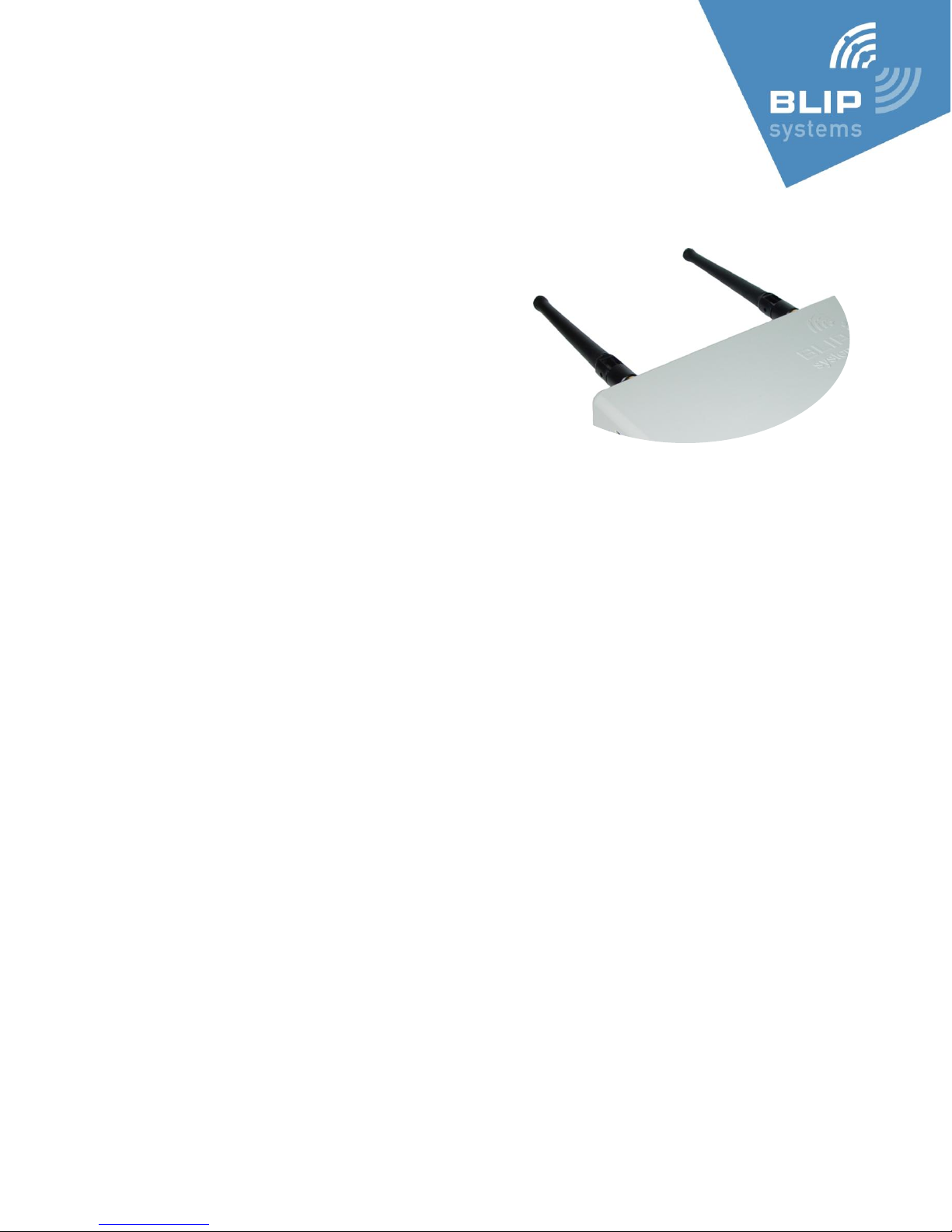
Antennas
Before inserting the power supply to the BlipNode L2i make sure both
antennas are mounted securely.
If you are using other antennas than the ones delivered with
the product make sure they have SMA female connector, are
suitable for 2.4 GHz and have an impedance of 50 Ω.
Power supply
Use the power supply delivered with the product. Power supplies for a BlipNode L1 should not be
used.
If you need to use another power supply: It must be 5V DC, 3 W. 2.1 mm pin connector with plus in
middle.
Power over Ethernet (PoE)
Before attaching the BlipNode L2i to your PoE switch: Make sure the switch is PoE 802.3af 48 V
compliant.
Connecting the BlipNode
Connecting to your local server
Connecting the BlipNode L2i to your local server attach it to the LAN your server resides on.
A DHCP Server is required. Make sure the BlipNode L2i is able to communicate with the server on
UPD port 9033 (incoming port on server), and that the server can do outgoing TCP connections (you
may need to edit your firewall settings).
Connecting to your remote server
To connect the BlipNode L2i to your remote server you can send BT1 Address and BT2 Address to
your contact person at BLIP Systems with the IP address or host name of your remote server.
The BlipNode L2i will be created on a Blip Name Server (BNS) by BLIP Systems, wherefrom the
BlipNode L2i will get the host name to connect to. When created in the BNS the BlipNode L2i will
automatically connect to your remote server after 5 minutes on your LAN.
This requires that the BlipNode L2i is allowed to do outgoing connections on TCP port 9032.
Page 2 of 9
Page 3
LED light / #
Power
Server
Bluetooth
GPRS
Off No power
Application not
running
No activity
No modem
connection
Mostly off,
shortly on
Linux Operating
System Running
Trying to get IP
address
Inquiry ongoing
Not used
Mostly on,
shortly off
Not used
Connecting to or
searching for
server
Connected and
inquiry ongoing
Not used
On
Kernel booting
Connected to
server
Connected
Connected
through GPRS
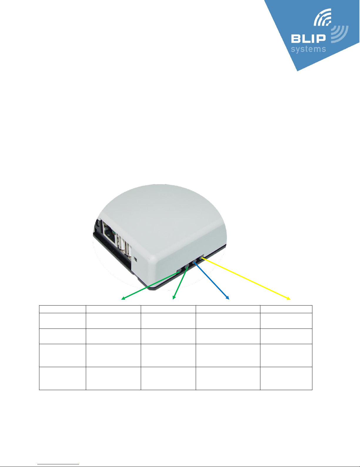
LED blinking sequence
The four Light Emitting Diodes (LEDs) on the side of the BlipNode L2i is used to describe the status of
the BlipNode L2i for 4 different functions:
Power (green)
Server (green)
Bluetooth (blue)
GPRS (yellow)
Page 3 of 9
Page 4
Changing Between Fixed and Dynamic IP Address
Via the BlipNode L2i’s built-in web server persistent settings can be read and changed.
This can be used to use a fixed IP address instead of retrieving IP address via DHCP (and vice versa).
By default the BlipNode will use DHCP.
Connect to the BlipNode:
In a web browser running on a PC on the same subnet as the BlipNode type in the IP address of the
BlipNode.
On the Windows platform you can also enter the MAC address. The MAC address is located on the
back of the BlipNode.
E.g. if the MAC address is 00:12:ca:01:03:6e you should type http://0012ca01036e/
Enable the telnet server:
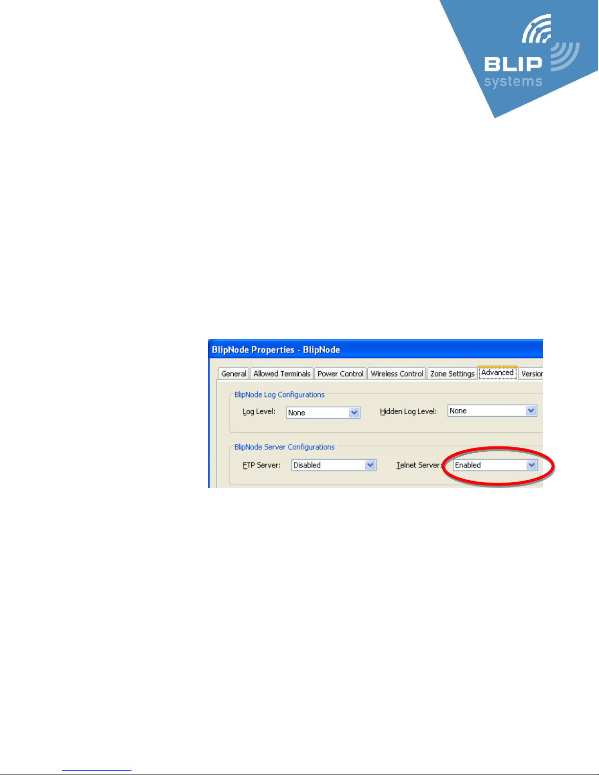
By default you can only view the settings of the BlipNode.
When you want to change the settings you need to enable the Telnet-server of Bluetooth Module 1
(the lowest Bluetooth
Address) of the BlipNode
(via the BlipManager ->
BlipNode Settings ->
Advanced -> Telnet Server)
…
The BlipNode will reboot
after this change.
If the BlipNode is not
connected to a BlipServer it
will automatically enable the telnet server after being turned on for 5 minutes.
When the telnet server is enabled:
Press the Settings link on the web-page (connected to in the previous section), and type in the new
settings (e.g. static IP settings).
Press the Submit. The BlipNode will reboot with the new settings.
If it fails to start up with the new settings it will revert to the previous settings after approximately 5
minutes.
Remember to disable the telnet server (via BlipManager) after the changes are completed.
Page 4 of 9
Page 5
Revert to default settings:
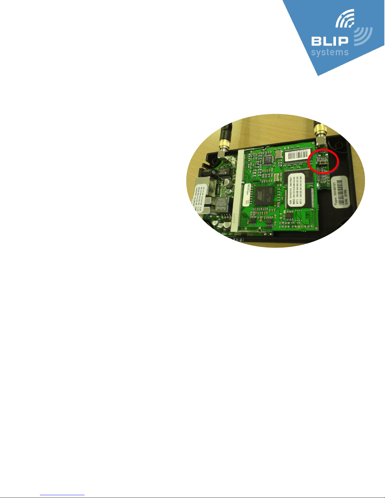
If you are not able to connect to the BlipNode, or the BlipNode IP address does not match your
current network you can revert to factory defaults by:
Opening the BlipNode cover.
Apply power and wait one minute for the
BlipNode to start-up.
Locate the button inside the BlipNode
(to the right in the picture below).
Press and hold the button for
between 3 and 10 seconds.
After releasing the reset button,
watch the green Power LED and verify
that it stops flashing, as the BlipNode
restarts with the default persistent
settings.
Page 5 of 9
Page 6
Mounting a BlipNode for Content Push
Place the BlipNode where your target users:
Gather
Have dwell time
Stands still
Set the range of the BlipNode so that the reach of the external signage matches the range of the
BlipNode (when the user sees the poster/screen informing about the service – the phone prompts).
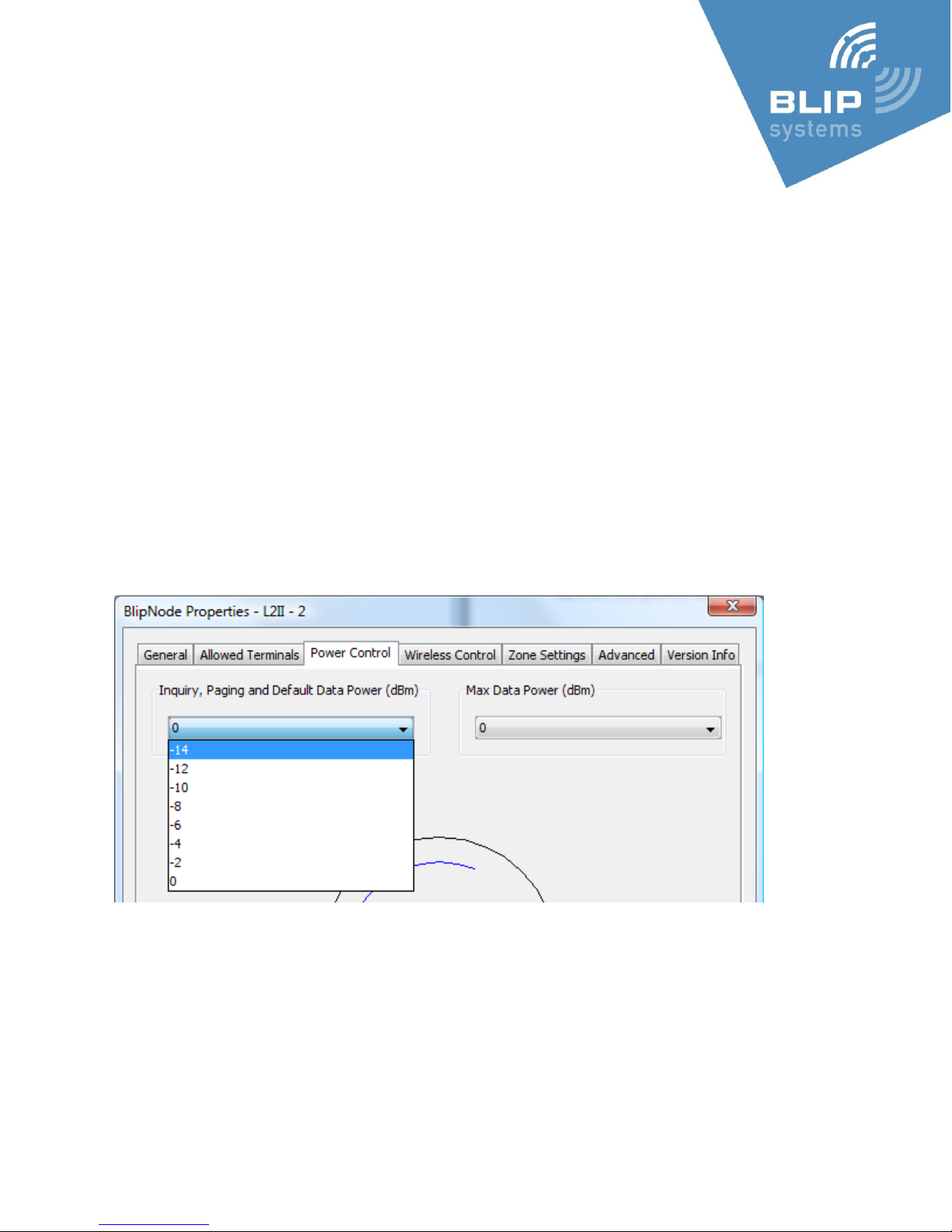
The range can be set both for the BlipNode itself (via the BlipManager, BlipNode Properties) – and
per message (via the BlipZones CMS).
Always use the Bluetooth module with the highest Bluetooth device address for inquiry (as this is
the module with the shortest range, adjustable to the shortest range – using the internal antenna).
-14 is approximately 5 meters range (phone and environment dependent)
0 is approximately 30 meters range (phone and environment dependent)
Mounting a BlipNode for Tracking
The BlipNodes should be placed where users pass by (e.g. by entrances).
As the tracking is zone based the number of BlipNodes determines the possible tracking resolution.
Page 6 of 9
Page 7
Connecting a BlipNode L2i via UMTS / HSDPA
networks
Prerequisites:
Huawei E220 USB modem
UMTS / HSDPA data account with a local (for the BlipNode) network supplier – preferably with an
unlimited usage plan (‘flat rate’)
Initial setup of USB modem and SIM card
Insert the SIM card in the USB modem and plug the modem into a Windows PC.
Follow the setup instructions from your broadband provider and use the modem to connect to the
internet. This way APN settings etc. will be written to the SIM card so the only configuration that is
needed in the BlipNode will a PIN code (if applied). It is also possible to enter the APN name in the
BlipNode settings – see below.
From the modem control application select a PIN code for the SIM card – you could also choose to
disable PIN code usage.
Entering PIN code and APN name in the BlipNode L2i
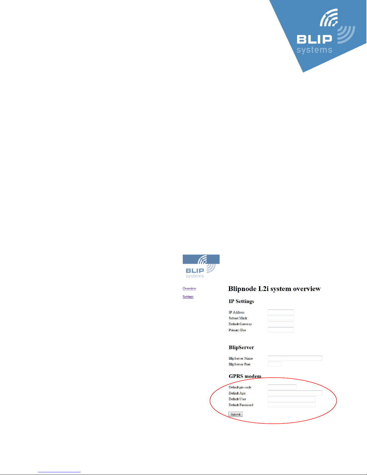
The PIN code for the SIM card is entered in the BlipNode L2i from the BlipNode’s built in web-page –
accessed as described previously in this guide.
On the settings page fill in the PIN code for the
SIM card.
If you disabled the PIN code from the USB
modem Control Application you do not have to
enter a PIN code for the SIM card in the
BlipNode L2i.
It is also possible to enter APN settings (APN,
User name and password) from the settings
page – please get the details from your
operator.
Connecting the BlipNode to the
internet using the modem
Disconnect the power from the BlipNode, insert
the modem in a USB port on the BlipNode L2i
and reconnect the power connector.
Page 7 of 9
Page 8

Within a short time the BlipNode L2i will connect to the internet through the
modem. You can see the connection status on the Yellow LED on the BlipNode L2i and on the
flashing LED on the USB modem as described in the USB modem User’s Manual (on the modem you
can e.g. see the connection speed)
Before returning a defect product
If the left most LED (green) is on, and no other LEDs are on or blinking it is very likely that the
processor-board inside the BlipNode has come loose of its connector (you can locate the processor
board as the board hanging above the main board).
Turn off the power and insert the board.
Contact BLIP Systems before returning any products.
Page 8 of 9
Page 9

Certification Information
This equipment complies with Part 15 of the FCC Rules. Operation is subject to the following two
conditions:
1. This device may not cause harmful interference, and
2. This device must accept any interference received, including interference that may
causeundesired operation.
This equipment has been tested and found to comply with the limits for a Class B digital device,
pursuant to Part 15 of the FCC Rules. These limits are designed to provide reasonable protection
against harmful interference in a residential installation. This equipment generates, uses, and can
radiate radio frequency energy and, if not installed and used in accordance with the instructions,
may cause harmful interference to radio communications. However, there is no guarantee that
interference will not occur in a particular installation. If this equipment does cause harmful
interference to radio or television reception, which can be determined by turning the equipment off
and on, the user is encouraged to try to correct the interference by one or more of the following
measures:
Reorient or relocate the receiving antenna
Increase the distance between the equipment and receiver
Connect the equipment into an outlet on a circuit different from that to which the receiver is
connected
Consult the dealer or an experienced radio or television technician for help
Changes or modifications made to this equipment not expressly approved by BLIP Systems A/S may
void the FCC authorization to operate this equipment.
To meet the FCC’s exposure rules and regulations:
Maintain a minimum distance of 20 cm from the equipment to the human body.
Page 9 of 9
 Loading...