

Page 1

BLiNQ Networks Inc.
X-1200 Intelligent Wireless Backhaul System
Installation Guide
Release 1.0
Issue 01 D1
April 2014
Page 2

BLiNQ Networks Inc. X-1200 System Installation Guide Release 1.0
Date
Issue
Reason for Issue
August 2013
01
Early Availability
January 2014
1.0
Final Document
April 2014
1.0 D1
Label Update (Approvals); Compliance update including Antenna
Contact Information:
BLiNQ Networks Inc.
400 March Road, Suite 240
Ottawa, ON K2K 3H4
Web Site:
http://www.blinqnetworks.com
Sales Inquiries:
Email: sales@blinqnetworks.com
Telephone: 1-613-599-3388 x280
Customer Support:
Web: http://www.blinqnetworks.com/support
Email: support@blinqnetworks.com
Telephone: 1-613-599-3388 x270
Revision History
Confidential - Restricted Use and Duplication Page ii Issue 01 D1
Page 3

BLiNQ Networks Inc. X-1200 System Installation Guide Release 1.0
Table of Contents
1 Important Safety and Service Notices ..........................................................................................1
1.1 Safety Warnings ............................................................................................................................ 1
1.2 Important Service and Warranty Information .............................................................................. 1
1.3 Overvoltage (Lightning/Surge) Protection .................................................................................... 2
2 System Description .....................................................................................................................4
3 Flowchart: Installation Process Overview ....................................................................................7
4 Required Installation Items .........................................................................................................8
5 Site Preparation........................................................................................................................ 11
5.1 Operating Sector Frequency Check ............................................................................................. 11
5.2 HM and RBM Pre-Installation Checks and Service Provisioning ................................................. 11
6 Installing the Modules (General) ............................................................................................... 13
6.1 General Safety Information ........................................................................................................ 13
6.2 Equipment Distance and Orientation ......................................................................................... 14
6.2.1 Hub Modules ....................................................................................................................... 14
6.2.2 Remote Backhaul Modules ................................................................................................. 14
6.3 Mounting to a Pole or Wall ......................................................................................................... 14
6.3.1 Attaching Pole Clamps to Mounting Bracket ...................................................................... 14
6.3.2 Mounting with U- or V-Clamps ........................................................................................... 16
6.3.3 Mounting with Steel Straps................................................................................................. 17
6.3.4 Mounting onto a Wall ......................................................................................................... 18
6.4 Assembling the Module Brackets ............................................................................................... 19
6.4.1 Attach Elevation Bracket ..................................................................................................... 19
6.4.2 Attach Azimuth Bracket ...................................................................................................... 21
6.5 Installing the Power Supply Unit (Optional) ............................................................................... 23
6.5.1 Installing the PSU Bracket ................................................................................................... 23
6.5.2 Installing the Power Supply Unit ......................................................................................... 24
6.6 Installing the Module onto a Mounting Bracket ......................................................................... 26
6.7 Grounding and Overvoltage Protection Instructions .................................................................. 28
6.7.1 Installing the Grounding Cable ............................................................................................ 28
6.7.2 Installing the Lightning/Surge Arrestor ............................................................................... 29
6.8 Connecting to DC Power ............................................................................................................. 31
6.9 Verifying Basic Installation .......................................................................................................... 33
6.10 Connecting to the Ethernet Backhaul Network .......................................................................... 34
6.10.1 Connecting to the RJ45 Ethernet Port ................................................................................ 34
6.10.2 Connecting to the SFP Port ................................................................................................. 36
6.11 Cable Management ..................................................................................................................... 36
Confidential - Restricted Use and Duplication Page iii Issue 01 D1
Page 4

BLiNQ Networks Inc. X-1200 System Installation Guide Release 1.0
7 Installing the Hub Module ......................................................................................................... 38
7.1 Adjusting the Hub Module .......................................................................................................... 38
7.2 Assembling the Beam Steering Antenna (If Required) ............................................................... 41
7.2.1 Installing the Bracket on to the Beam Steering Antenna ................................................... 41
7.2.2 Mounting the Antenna Assembly on to HM ....................................................................... 42
7.2.3 Connections for Antenna and Hub...................................................................................... 44
8 Installing the Remote Backhaul Module .................................................................................... 46
8.1 Using the BSI Feature and Adjusting the Module ....................................................................... 46
9 System and Network Provisioning ............................................................................................. 51
10 Appendix .................................................................................................................................. 52
10.1 BLiNQ Wireless Devices and RF Safety/Les appareils sans fil BLiNQ et la sécurité RF................ 52
10.2 Equipment Compliance ............................................................................................................... 54
10.2.1 Federal Communications Commission (FCC) Notices ......................................................... 54
10.2.2 Industry Canada Notice ....................................................................................................... 54
10.2.3 Bonded Network ................................................................................................................. 54
10.3 Troubleshooting Guide ............................................................................................................... 55
10.4 List of Acronyms .......................................................................................................................... 57
List of Figures
Figure 1 Module Casing Labels .................................................................................................................................... 2
Figure 2 Hub Module ................................................................................................................................................... 6
Figure 3 Remote Backhaul Module .............................................................................................................................. 6
Figure 4 Pole/Wall Mount Bracket............................................................................................................................. 15
Figure 5 Attaching Pole Clamps to Pole/Wall Mount Bracket ................................................................................... 15
Figure 6 Attaching Assembled Pole/Wall Mount Bracket to Pole with U-Clamp or V-Clamp.................................... 17
Figure 7 Attaching Assemble Pole/Wall Mount Bracket to Pole with Straps ............................................................ 18
Figure 8 Attaching Assembled Pole/Wall Mount Bracket to Wall ............................................................................. 19
Figure 9 Elevation Bracket and Associated Hardware ............................................................................................... 20
Figure 10 Elevation Bracket Mounting Position ......................................................................................................... 20
Figure 11 Attaching Elevation Bracket to Back of Module ........................................................................................ 21
Figure 12 Azimuth Bracket and Associated Hardware ............................................................................................... 21
Figure 13 Attaching Azimuth Bracket to Elevation Bracket on Module ..................................................................... 22
Figure 14 PSU Mounting Bracket ............................................................................................................................... 23
Figure 15 Attaching PSU Bracket to Back of Module ................................................................................................. 24
Figure 16 Power Supply Unit (PSU) ............................................................................................................................ 24
Figure 17 PSU Bracket PSU Mounting Studs .............................................................................................................. 25
Figure 18 Power Connection via the PSU................................................................................................................... 26
Figure 19 Module with PSU Installed. ........................................................................................................................ 26
Figure 20 Pole/Wall Mount Bracket Locknut Hardware ............................................................................................ 26
Figure 21 Unit Installed onto the Pole/Wall Mount Bracket ..................................................................................... 27
Confidential - Restricted Use and Duplication Page iv Issue 01 D1
Page 5

BLiNQ Networks Inc. X-1200 System Installation Guide Release 1.0
Figure 22 Module with Grounding Lug ...................................................................................................................... 29
Figure 23 Wiring of Lightning/Surge Arrester (Sold by BLiNQ Networks) .................................................................. 31
Figure 24 HM and RBM LED States ............................................................................................................................ 33
Figure 25 Ethernet Connector Encased in Environmental Housing ........................................................................... 34
Figure 26 Ethernet Connector Assembly - Separated ................................................................................................ 35
Figure 27 Module Cable Management ...................................................................................................................... 37
Figure 28 Hub Module Showing All Connectors ........................................................................................................ 38
Figure 29 HM Horizontal Plane Adjustment via Azimuth Bracket ............................................................................. 39
Figure 30 HM Vertical Plane Adjustment via Elevation Bracket ................................................................................ 39
Figure 31 HM Theta Adjustment Via Elevation Bracket Mounting Holes .................................................................. 40
Figure 32 HM Down-tilt Adjustment with Antenna Mount ....................................................................................... 40
Figure 33 Beam Steering Antenna Mounting Bracket ............................................................................................... 41
Figure 34 Hub Module Antenna Mounting Holes ...................................................................................................... 43
Figure 35 Antenna attached to a Hub Module .......................................................................................................... 43
Figure 36 Beam Steering Antenna RF Connections ................................................................................................... 44
Figure 37 RF Connections on the Hub Module .......................................................................................................... 44
Figure 38 RBM Module Showing All Connectors ....................................................................................................... 46
Figure 39 RBM Horizontal Plane Adjustment via Azimuth Bracket ........................................................................... 48
Figure 40 RBM Vertical Plane Adjustment via Elevation Bracket .............................................................................. 48
Figure 41 RBM Theta Adjustment Via Elevation Bracket Mounting Holes ................................................................ 49
List of Tables
Table 1 X-1200 System Specifications .......................................................................................................................... 4
Table 2 Required Items for Hub Module Installation .................................................................................................. 8
Table 3 Required Items for Remote Backhaul Module Installation ............................................................................. 9
Table 4 Summary of Required Installation Tools (Not Provided by BLiNQ Networks) ................................................ 9
Table 5 Recommended Torque Values for Self-Tapping Bolts ................................................................................... 15
Table 6 Recommended Torque Values for U-Bolt or V-Clamp Bolts ......................................................................... 16
Table 7 Recommended Torque Values for Elevation Bracket Bolts ........................................................................... 20
Table 8 Recommended Torque Values for Azimuth Bracket Bolts ............................................................................ 22
Table 9 Recommended Torque Values for PSU Bracket Bolts ................................................................................... 23
Table 10 Recommended Torque Values for PSU Bolts .............................................................................................. 25
Table 11 Recommended Torque Values for Pole/Wall Mount Bracket Locknuts ...................................................... 27
Table 12 Recommended Torque Value for the RJ45 Ethernet Connection ............................................................... 34
Table 13 Recommended Torque Values for HM Bracket Bolts .................................................................................. 39
Table 14 Recommended Torque Values for Antenna Bracket Nuts .......................................................................... 42
Table 15 Recommended Torque Values for Antenna Bracket Bolts .......................................................................... 42
Table 16 Recommended Torque Values for Antenna Cable Connections ................................................................. 44
Table 17 Recommended Torque Values for RBM Bracket Bolts ................................................................................ 47
Table 18 X-1200 System Troubleshooting Guide ....................................................................................................... 55
Table 19 List of Acronyms .......................................................................................................................................... 57
Confidential - Restricted Use and Duplication Page v Issue 01 D1
Page 6

BLiNQ Networks Inc. X-1200 System Installation Guide Release 1.0
This Page Intentionally Left Blank.
Confidential - Restricted Use and Duplication Page vi Issue 01 D1
Page 7
BLiNQ Networks Inc. X-1200 System Installation Guide Release 1.0
WARNING!
Follow all health and safety procedures and recommendations made by
BLiNQ Networks within this X-1200 System Installation Guide. Failure
to do so could result in injury, death, or damage to the equipment.
!
1 Important Safety and Service Notices
Read this X-1200 System Installation Guide and follow all operating and safety instructions.
Installation of the X-1200 system must be done by a qualified professional installer who is experienced
with installing telecommunications equipment and networks. Installations must adhere to the
information and specifications within this X-1200 System Installation Guide.
1.1 Safety Warnings
The product-marketing label indicates the power requirements. Do not exceed the described
limits.
Each module’s power supply must have a resettable circuit breaker rated to a maximum of 20
Amps.
The antenna must be permanently grounded before making any of the connections to the
antenna used with the Hub.
Use only a damp cloth for cleaning. Do not use liquid or aerosol cleaners. Disconnect the power
before cleaning.
Disconnect the power when the unit is stored for long periods.
Do not locate the outdoor unit near power lines or other electrical power circuits.
The system must be properly grounded to protect against power surges and accumulated static
electricity. It is the user’s responsibility to install this device in accordance with the local electrical
codes.
1.2 Important Service and Warranty Information
Keep all product information for future reference.
Refer all repairs to qualified service personnel. Do not remove the covers or modify any part of the
X-1200 system, as this action will void the warranty.
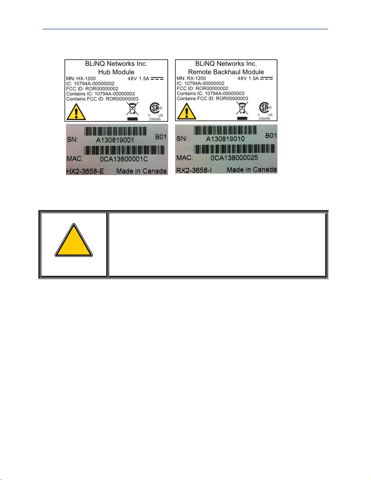
Be sure to do the following upon unpacking the X-1200 system modules. For each Hub Module (HM) and
Remote Backhaul Module (RBM) in your system:
Locate the label on the module casing that lists the Serial Number (SN) and Media Access Control
(MAC) address for the module (Figure 1, “Module Casing Labels”)
Record the SN on your registration card for future reference
Record the MAC address for future reference when provisioning the system
Confidential - Restricted Use and Duplication Page 1 Issue 01 D1
Page 8
BLiNQ Networks Inc. X-1200 System Installation Guide Release 1.0
WARNING!
A qualified professional installer should install the wireless equipment.
The installer must follow local and national codes for electrical
grounding and safety. Failure to meet safety requirements and/or use
of non-standard practices and procedures could result in personal
injury and damage to equipment. A direct lightning strike may cause
serious damage even if these guidelines are followed.
!
Figure 1 Module Casing Labels
1.3 Overvoltage (Lightning/Surge) Protection
All outdoor wireless equipment is susceptible to lightning damage from a direct hit or induced current
from a near strike. Lightning protection and grounding practices in local and national electrical codes
serve to minimize equipment damage, service outages and serious injury. Reasons for lightning damage
can be summarized as follows:
Poorly grounded antenna sites that can conduct high lightning strike energy into equipment.
Lack of properly installed lightning protection equipment that can cause equipment failures from
lightning induced currents.
An overvoltage protection system provides a means by which the energy may enter earth without
passing through and damaging parts of a structure. An overvoltage protection system does not prevent
lightning from striking; it provides a means for controlling it and preventing damage by providing a low
resistance path for the discharge of energy to travel safely to ground. Improperly grounded connections
are also a source of noise that can cause sensitive equipment to malfunction.
A good grounding system disperses most of the surge energy from a lightning strike away from the
building and equipment. The remaining energy on the cable can be directed safely to ground through a
lightning/surge arrestor in series with the cable.
Confidential - Restricted Use and Duplication Page 2 Issue 01 D1
Page 9

BLiNQ Networks Inc. X-1200 System Installation Guide Release 1.0
The X-1200 system is designed with consideration for resistance to the effects of lightning on the access
point electronics. When installing a lightning/surge arrestor for your system installation, observe the
following general industry practices:
Install lightning/surge arrestors in series with the Ethernet and power cables at the point of entry
to the building. If the power cable does not enter the building, the location is at the installer’s
discretion.
In each case the grounding wire should be connected to the same termination point used for the
tower or mast.
Provide direct grounding from the unit, the mounting bracket, the antenna, and the Ethernet
cable surge protection to the same ground bus on the building. Use the grounding screws
provided for terminating the ground wires.
Confidential - Restricted Use and Duplication Page 3 Issue 01 D1
Page 10

BLiNQ Networks Inc. X-1200 System Installation Guide Release 1.0
RADIO SPECIFICATIONS
Frequency Band
3.65-3.70 GHz, 3.40-3.60 GHz, 2.50-2.69 GHz, and 5.47-5.875 GHz
Tuning Resolution
50 kHz, minimum
Transmit Power, 3.65 GHz
-15 dBm to +27 dBm per port, 0.25 dB resolution
Transmit Power, 5.8 GHz
-15 dBm to +23 dBm per port, 0.25 dB resolution
Channel Bandwidth
20 MHz (5/10 MHz1)
Receiver Sensitivity
-92 dBm with QPSK @ 1e-03 PER (typ.)
Modulation & Coding
QPSK/16QAM/64QAM/256QAM, bi-directional, fully adaptive
PERFORMANCE
Throughput
Up to 400 Mbps, L2 aggregate uplink and downlink
Spectral Efficiency
11 bps/Hz
Physical Layer
Cyclic Single Carrier Frequency Domain Equalized
Operating Mode
TDD
Latency
3.5 msec for 4 RBM’s assigned to Hub, dual carrier mode
Traffic ratios
50:50, 65:35, 75:25, 35:65, 25:75; user configurable
Frame Size
Up to 2016 bytes
1
2 System Description
The X-1200 is a dual carrier, Point-to-Multipoint (PMP) intelligent wireless transport system
distinguished for its high performance and advanced traffic management capabilities. The X-1200
platform consists of a Hub Module (HM) and up to four (eight1) Remote Backhaul Modules (RBM).
BLiNQ Networks X-1200 system operates in the sub 6 GHz licensed frequency bands. It offers
deployment flexibility for both Line-of-Sight (LOS) and Non Line-of-Sight (TrueNLOS™) operation by
incorporating advanced Physical Layer (PHY) and Media Access Control (MAC) layer algorithms and
techniques. BLiNQ Networks has developed proprietary interference mitigation algorithms and
incorporated self-organizing network techniques into its solutions to increase capacity and reliability
beyond that of ordinary backhaul solutions. This is because in a NLOS environment, interference and
shadowing are the two main reasons that limit capacity and link reliability. Mitigating interference and
enhancing signal reliability maximizes system performance.
The X-1200 system delivers 11 bps/Hz spectral efficiency. The system is designed for use in multiple
applications that include small cell mobile backhaul, optical fiber cable extension and enterprise data
backhaul services by providing up to 400 Mbps of throughput in dual 2x20 MHz channels.
Table 1 lists the system specifications.
Table 1 X-1200 System Specifications
Future Software Release
Licensed:+26dBm for MCS 7 and +25dBm for MCS 8; Unlicensed: +22dBm for MCS 6, +21 for MCS 7 and +20 for MCS 8
Confidential - Restricted Use and Duplication Page 4 Issue 01 D1
Page 11

BLiNQ Networks Inc. X-1200 System Installation Guide Release 1.0
PERFORMANCE (Cont)
Antenna System
2x2 MIMO, Spatial Multiplexing / Tx & Rx Diversity
Remote Backhaul Module: Integral antenna, 14 dBi
Hub Module: Beam Steering Antenna, 17 dBi
Configuration
PTP or PMP up to 42 Remotes
Power Consumption
< 72 W
Power
-48 Vdc nominal, -36 to -60 Vdc range
Connectivity
Copper 1000BaseT
Optional Fiber Gig-E (Hub only)
Synchronization
Integral GPS antenna and receiver, 1588v2, SyncE
QoS
8 queues per service flow, 4 SF’s per RBM per direction
Security
AES-256
NETWORKING
Configuration
Ethernet bridge
Attributes
802.1Q, 802.1ad, DSCP/ToS/802.1p (IPv4/IPv6)
Features
Per RBM service flows, Dynamic Bandwidth Sharing
OPERATIONS, ADMINISTRATION AND MANAGEMENT (OAM)
Configuration
WebUI / CLI, radio and Ethernet performance monitoring
EMS Integration
SNMP v2c/v3
OAM Protocols
HTTP(S), TCP/IP, UDP, (S)FTP, SSH
MECHANICAL/ENVIRONMENTAL/COMPLIANCE
RBM Dimensions
12.6” x 8.3” x 5.1” (32 x 21 x 13 cm)
Hub Dimensions
15.0” x 18.0” x 5.1” (38 x 46 x 13 cm)
Weight (Hub & RBM)
RBM < 8.8 lbs. (4.0 kg); Hub < 15.5 lbs. (7.0 kg)
Temperature Range
-45°C to +55°C (-49 °F to 131 °F)
Enclosure Protection
IP67
Compliance
EMC: FCC Part 15 Subpart B, C, E; ICES-003 Class B
Radio: FCC Part 90z, RSS 197
Safety: UL/CSA 60950-1,-22
2
The X-1200 system operates in licensed Time Division Duplexing (TDD) bands including 3.65-3.70 GHz,
3.40-3.60 GHz, 2.50-2.69 GHz bands in both Point-to-Point (PTP) and Point-to-Multipoint (PMP)
configurations. Additionally, the X-1200, when configured for dual-carrier mode, operates in unlicensed
frequency bands including 5.47-5.875 GHz bands. It incorporates Multiple Input Multiple Output
(MIMO) technology and operates at high Modulation and Coding Scheme (MCS) rates to provide high
capacity. In addition, the product incorporates BLiNQ Networks interference management techniques
which include multiple power control algorithms to maximize performance in dense networks.
8 in future release
Confidential - Restricted Use and Duplication Page 5 Issue 01 D1
Page 12
BLiNQ Networks Inc. X-1200 System Installation Guide Release 1.0
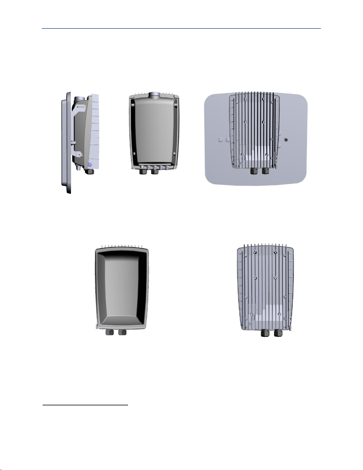
Front
Back
Front without Antenna
Back
Side
The X-1200 system has a small, all-outdoor, zero-footprint form factor that can be easily deployed
unobtrusively on towers, poles, building sidewalls or rooftops. It consists of the following modules:
Hub Module (HM): A sector controller which serves as the aggregation point controlling up to 4
Remote Backhaul Modules (RBMs), featuring an integral Beam Steering Antenna.
Figure 2 Hub Module
Remote Backhaul Module (RBM): A subscriber unit that is installed outdoors on customer
premises, including public infrastructure assets such as light and utility poles in mobile backhaul
applications. RBMs feature an integrated antenna.
8 in future software release.
Confidential - Restricted Use and Duplication Page 6 Issue 01 D1
Figure 3 Remote Backhaul Module
Page 13

BLiNQ Networks Inc. X-1200 System Installation Guide Release 1.0
Start
Important
Safety and
PAGE 1
Installation
Preparation
the Modules
13
Installing the
PAGE 46
System and
Provisioning
Warnings
Service and
Information
(Lightning/Surge)
Protection
Check
Installation
Checks and
Provisioning
Information
Module
BSI Feature
the Module
Equipment
Orientation
Mounting to
Wall
Assembling
the Module
Brackets
Supply Unit
(Optional)
the Module
Bracket
Grounding
Overvoltage
Protection
Instructions
to DC Power
Installation
Connecting
Network
END
Assembling
Antenna (If
Required)
Management
3 Flowchart: Installation Process Overview
To get started quickly, follow the process below. For more details, click on the chapter/section title.
Service
Notices
Safety
Important
Warranty
Overvoltage
Required
Items
PAGE 8
Site
PAGE 11
Operating
Sector
Frequency
HM and
RBM Pre-
Service
Installing
(General)
PAGE
General
Safety
Distance
and
a Pole or
Installing
the Hub
Module
PAGE 38
Adjusting
the Hub
the Beam
Steering
Remote
Backhaul
Module
Using the
and
Adjusting
Network
PAGE 51
Installing
the Power
Installing
onto a
Mounting
and
Connecting
Verifying
Basic
to the
Ethernet
Backhaul
Cable
Confidential - Restricted Use and Duplication Page 7 Issue 01 D1
Page 14

BLiNQ Networks Inc. X-1200 System Installation Guide Release 1.0
No.
Description
Quantity
Note
1
X-1200 Hub Module (HM)
Beam Steering Antenna Kit includes Antenna unit, Down-tilt antenna
bracket, screws, nuts and washers for mounting to X-1200 unit, SPI
control cable (x1), and RF cables NType to NType (x4)
1
2
X-1200 Module Mount Kit with Self-Tapping Screw Bolts—Includes
module elevation bracket, module azimuth bracket, two pole clamps,
and pole/wall mount bracket
1*
Screws not
provided for
wall/mast side
(1/4 in. holes)
3
Coaxial RF Cables: N-type male termination at both ends, outdoor rated
2 or 4*
Nominal 1 m long
4
Outdoor-rated Shielded Ethernet cable, CAT5e or better
< 100
meters
Not provided by
BLiNQ Networks
5
Ethernet cable connector and environmental housing with shielded
RJ45 connectors
1
Provided by
BLiNQ Networks
6
SFP, fiber and connectors (if optional fiber optic Ethernet possibility is
to be used)
Not provided by
BLiNQ Networks
7
Power Cable:
Shielded 18 AWG 2 conductors 90C water resistant, black and white
conductor jackets, outdoor rated cable, 5-8 mm thick
Power Connector:
Weatherized DC connector to fit on power cable
1*
Option of 10m,
20m, 40m
terminated
cables
8
6-gauge grounding cable
1
Not provided by
BLiNQ Networks
9
Power Supply Unit (PSU) Kit includes PSU, PSU bracket and associated
hardware for installation.
1*
Optional
10
Lightning/Surge Arrester
1*
Optional
11
Access to NOC Server, Providing FTP, SysLog, SNMP Browser, and DNS
Services
1
12
Basic Portable Personal Computer (PC); with NIC (Ethernet) port
required
1
Not Provided by
BLiNQ Networks
13
Miscellaneous hardware and software as required: for example,
compass, sniffer application, FTP client
as
required
Not Provided by
BLiNQ Networks
*Sold as a separate line item by BLiNQ Networks.
4 Required Installation Items
Table 2 lists the items required to install the X-1200 Hub Module (HM).
Table 3 lists the items required to install the X-1200 Remote Backhaul Module (RBM).
Table 4 lists the tools required to install the X-1200 system modules.
Table 2 Required Items for Hub Module Installation
Confidential - Restricted Use and Duplication Page 8 Issue 01 D1
Page 15

BLiNQ Networks Inc. X-1200 System Installation Guide Release 1.0
No.
Description
Quantity
Note
1
X-1200 Remote Backhaul Module (RBM)
1
Per site
2
X-1200 Module Mount Kit with Self-Tapping Screw Bolts—Includes
module elevation bracket, module azimuth bracket, two pole
clamps, and pole/wall mount bracket
1*
Screws not provided
for wall/mast side
(1/4 in. holes)
3
Outdoor-rated Shielded Ethernet cable, CAT5e or better
< 100
meters
Not provided by
BLiNQ Networks
4
Ethernet cable connector and environmental housing with shielded
RJ45 connectors
1
Provided by BLiNQ
Networks
5
Power Cable:
Shielded 18 AWG 2 conductors 90C water resistant, black and
white conductor jackets, outdoor rated cable, 5-8 mm thick
Power Connector:
Weatherized DC connector to fit on power cable
1*
Option of 10m, 20m,
40m connectorized
cables
6
6-gauge grounding cable
1
Not provided by
BLiNQ Networks
7
Lightning/Surge Arrester
1*
Optional
8
Access to NOC Server, Providing FTP, SysLog, SNMP Browser, and
DNS Services
1
9
Basic Portable Personal Computer (PC); with NIC (Ethernet) port
required
1
Not provided by
BLiNQ Networks
10
Miscellaneous hardware and software as required:
for example, wrench, compass
as required
Not provided by
BLiNQ Networks
11
Power Supply Unit (PSU) Kit includes PSU, PSU bracket and
associated hardware
1 each*/
RBM
Optional
*Sold as a separate line item by BLiNQ Networks.
No.
Description
1
Socket wrench with 3/8 in. driver head, with long and short ½ in. and 7/16 in. sockets
2
Slot head screwdrivers, small and medium size
3
Phillips #2 screwdriver
4
Torque wrench, 3/8 in. head with range for 4-60Nm or 3-45lbf-ft
5
Ratchet wrenches, ½ in. and 7/16 in.
6
Steel straps (for installation on pole diameters 3.5 in./9 cm or larger)
7
Four 5/16 in. or M8 wall mounting bolts, or equivalent, for wall installation (and bolt reinforcement
hardware if wall material requires it)
8
Black marker
9
Crimp tool
10
Cable ties
11
Torque screwdriver ¼ head with 5-40inlb range
12
Allen drivers metric 3mm and SAE 3/16” for GND lug and Beam Steering Antenna bracket
Table 3 Required Items for Remote Backhaul Module Installation
Table 4 Summary of Required Installation Tools (Not Provided by BLiNQ Networks)
Confidential - Restricted Use and Duplication Page 9 Issue 01 D1
Page 16

BLiNQ Networks Inc. X-1200 System Installation Guide Release 1.0
No.
Description
13
Metric 7mm nut driver (socket) for the power supply mounting nuts
14
Metric 8mm nut driver (socket) for Beam Steering Antenna studs mounting to bracket
Confidential - Restricted Use and Duplication Page 10 Issue 01 D1
Page 17

BLiNQ Networks Inc. X-1200 System Installation Guide Release 1.0
5 Site Preparation
To prepare the installation site, perform the following checks prior to installation of an X-1200 Hub
Module (HM) or Remote Backhaul Module (RBM).
Section 5.1, “Operating Sector Frequency Check”, page 11
Section 5.2, “HM and RBM Pre-Installation Checks and Service Provisioning”, page 11
5.1 Operating Sector Frequency Check
The operating frequency must be determined prior to the installation and be based on a cell site
frequency plan. BLiNQ Networks strongly advises that a comprehensive site survey be performed before
installation to determine the optimum antenna orientation and identify any potential source of
interference.
5.2 HM and RBM Pre-Installation Checks and Service
Provisioning
This section requires use of the BLiNQ X-1200 WebUI. The X-1200 WebUI is the configuration tool for
use with X-1200 HMs and RBMs. It is a standard web application that runs directly on the X-1200
equipment through the default port for HTTP (that is, port 80), and is accessible at URL http://<IP of the
node>.
For instructions on how to use the X-1200 WebUI, refer to the X-1200 System User Guide. The default
username and password for access is: admin.
Browser support for X-1200 WebUI:
Mozilla Firefox
Internet Explorer 9 (IE9)
WebKit-based browsers, for example:
Apple Safari
Google Chrome
Operating System (OS) support for X-1200 WebUI:
Windows
Mac OS X
Linux
Note: With the exception of IE9, both web browser and OS support for the X-1200 WebUI always refer
to the most recent versions.
The default configuration settings on the HM and RBM include:
Fixed, non-routable local craft IP address: 169.254.1.1
Management IP address: 192.168.26.2
Operating Frequency (e.g. 3.65 GHz)
Channel bandwidth (20 MHz)
Confidential - Restricted Use and Duplication Page 11 Issue 01 D1
Page 18

BLiNQ Networks Inc. X-1200 System Installation Guide Release 1.0
Uplink/downlink TDD ratio on the Hub
Preamble series index value
RF transmitter disabled on the HM (not transmitting)
Perform the following pre-installation checks and service provisioning on the HM and RBMs:
1. Verify the modules can be powered up and Ethernet connectivity can be established.
2. Verify and record the Media Access Control (MAC) address of each RBM unit (located on the label
on the outside of the unit).
3. Using the X-1200 WebUI for HMs:
a. Verify the configuration settings on the HM and update if necessary.
b. Verify the active software version on the HM and upgrade if necessary.
c. To allow the HM to go into service after installation, provision these HM radio operation
parameters through the ‘Setup > Radio Interface Page’ either before or after installation:
Radio Administrative State (set to ‘Enabled’)
RF Frequency
Max. Transmit Power
Preamble Phase Index (Optional)
Rate Adaption (Optional)
d. (Optional) Provision these HM system parameters as needed through the ‘Setup > System Page’
either before or after installation:
System Identification (including Name, Location, Contact, Description)
Ethernet Port Configuration
Management Interface IP Address
For more information, refer to the X-1200 System User Guide.
4. Using the X-1200 WebUI for RBMs:
a. Verify the configuration settings on each RBM and update if necessary.
b. Verify the active software version on each RBM and upgrade if necessary.
c. To allow the RBM to go into service after installation, provision these RBM radio operation
parameters through the ‘Setup > Radio Interface Page’ either before or after installation:
Radio Administrative State (set to ‘Enabled’)
d. (Optional) Provision these RBM system parameters as needed through the ‘Setup > System Page’
either before or after installation:
System Identification (including Name, Location, Contact, Description)
Ethernet Port Configuration
Management Interface IP Address
For more information, refer to the X-1200 System User Guide.
Confidential - Restricted Use and Duplication Page 12 Issue 01 D1
Page 19
BLiNQ Networks Inc. X-1200 System Installation Guide Release 1.0
WARNING!
Installation of the equipment must comply with local and national
electrical codes.
Personnel mounting the equipment must understand grounding
methods.
!
6 Installing the Modules (General)
As needed, refer to these sections and follow these steps to properly install either the Hub Module (HM)
or Remote Backhaul module (RBM):
Section 6.1, “General Safety Information”, page 13
Section 6.2, “Equipment Distance and Orientation”, page 14
Section 6.3, “Mounting to a Pole or Wall”, page 14
Section 6.3.1, “Attaching Pole Clamps to Mounting Bracket”, page 16
Section 6.3.2, “Mounting with U- or V-Clamps”, page 17
Section 6.3.3, “Mounting with Steel Straps”, page 17
Section 6.3.4, “Mounting onto a Wall”, page 18
Section 6.4, “Assembling the Module Brackets”, page 19
Section 6.4.1, “Attach Elevation Bracket”, page 19
Section 6.4.2, “Attach Azimuth Bracket”, page 21
Section 6.5, “Installing the Power Supply Unit (Optional)”, page 23
Section 6.6, “Installing the Module onto a Mounting Bracket”, page 26
Section 6.7, “Grounding and Overvoltage Protection Instructions”, page 28
Section 6.8, “Connecting to DC Power”, page 31
Section 6.9, “Verifying Basic Installation”, page 33
Section 6.10, “Connecting to the Ethernet Backhaul Network”, page 34
Section 6.11, “Cable Management”, Page 36
6.1 General Safety Information
Before performing any of the tasks in this chapter, read the safety warnings and service notices in
Chapter 1, “Important Safety and Service Notices”.
The system requires one person to properly and safely install the X-1200 system modules.
Confidential - Restricted Use and Duplication Page 13 Issue 01 D1
Page 20

BLiNQ Networks Inc. X-1200 System Installation Guide Release 1.0
6.2 Equipment Distance and Orientation
6.2.1 Hub Modules
Locate the Hub Module (HM) with as much distance as possible from other transmitting equipment.
The installer must mount the Beam Steering Antenna on the HM, as it can not be remotely mounted.
The HM must also have clear view of the sky for its Global Positioning System (GPS) antenna (located on
top of the unit) to work and to synchronize transmissions with other HMs.
When mounting the HM, ensure it is oriented so that the cable connectors/connections point downward
and the GPS antenna points upward.
6.2.2 Remote Backhaul Modules
When installing multiple Remote Backhaul Modules (RBMs), the distance required between the RBMs
depends on the average transmit power in use by the RBMs. Contact your supplier for the
recommended distance between RBMs for your particular installation.
When mounting the RBMs, ensure they are oriented so that the power cable connectors point
downward.
6.3 Mounting to a Pole or Wall
The following sections describe how to attach a mounting bracket to either a pole or wall:
Section 6.3.1, “Attaching Pole Clamps to Mounting Bracket”; recommended for pole diameters
up to 4 in./10 cm.
Section 6.3.2, “Mounting with U- or V-Clamps”; recommended for pole diameters up to
4 in./10 cm
Section 6.3.3, “Mounting with Steel Straps”; recommended for pole diameters up to 3.5 in./9 cm
or larger
Section 6.3.4, “Mounting onto a Wall”
6.3.1 Attaching Pole Clamps to Mounting Bracket
Use the pole clamps with pole/wall mounting brackets for pole diameters up to 4 in./10 cm. If the pole is
larger, see Section 6.3.3, “Mounting with Steel Straps”.
Required parts and tools:
Two pole clamps, pole/wall mount bracket (Figure 4, “Pole/Wall Mount Bracket”)
Socket wrench with 3/8 in. driver head, with long and short ½ in. and 7/16 in. sockets
Torque wrench, 3/8 in. head with range for 4-60Nm or 3-45lbf-ft
Confidential - Restricted Use and Duplication Page 14 Issue 01 D1
Page 21

BLiNQ Networks Inc. X-1200 System Installation Guide Release 1.0
Item
Description
Torque
Note
1
Self-tapping bolts (x2)
27.1Nm or 20lbf-ft
—
Front View
Back View
Self-Tapping
Bolts
Orientation
Cut-out (Up)
Figure 4 Pole/Wall Mount Bracket
Table 5 Recommended Torque Values for Self-Tapping Bolts
To attach the two pole clamps to the pole/wall mount bracket, refer to Figure 5 and follow these steps:
1. Place the pole clamps within the top and bottom of the pole/wall mounting bracket, aligning the
bolt holes of the clamps with those of the bracket.
2. Use the socket wrench to lightly tighten the self-tapping bolts through the clamp holes into the
holes on the back of the bracket (do not over tighten).
3. Use the torque wrench to tighten down the self-tapping bolts and finish the installation of the pole
clamps to the pole/wall mount bracket (do not over tighten). See Table 5 for torque values.
Note: Pole clamps are not required for pole diameters greater than 4 in./10 cm.
Figure 5 Attaching Pole Clamps to Pole/Wall Mount Bracket
Confidential - Restricted Use and Duplication Page 15 Issue 01 D1
Page 22

BLiNQ Networks Inc. X-1200 System Installation Guide Release 1.0
Item
Description
Torque
Note
1
U- or V-Clamp bolts (x4)
16.3Nm or 12lbf-ft
—
6.3.2 Mounting with U- or V-Clamps
Use the U- or V-clamps for pole diameters up to 4 in./10 cm. If the pole is larger, see Section 6.3.3,
“Mounting with Steel Straps”.
Required parts and tools:
Pole/wall mount bracket with attached pole clamps; see Section 6.3.1, “Attaching Pole Clamps to
Mounting Bracket”
Two U- or V-clamps (use one type or the other; do not mix) and associated hardware, both sized
either 1.5 in./4 cm, 2 in./5 cm, 2.5 in./6 cm, 3 in./8 cm, 3.5 in./9 cm, or 4 in./10 cm to match pole
diameter at installation site
Socket wrench with ½ in. socket
Torque wrench, 3/8 in. head with range for 4-60Nm or 3-45lbf-ft
Table 6 Recommended Torque Values for U-Bolt or V-Clamp Bolts
To install the pole/wall mount bracket onto a vertical pole up to 4 in. (10 cm) in diameter using U-clamps
or V-clamps, refer to Figure 6, “Attaching Assembled Pole/Wall Mount Bracket to Pole with U-Clamp or
V-Clamp” and follow these steps:
1. Select a mounting location on the pole and place the pole clamp notches from the assembled
pole/wall mounting bracket against the pole. Ensure the orientation cut-out is pointing up (see
Figure 4, “Pole/Wall Mount Bracket”).
2. Insert one U-bolt or V-bolt through the top of the pole/wall mount bracket. Install the washers and
then hand-tighten the nuts.
3. Insert a second U-bolt or V-bolt through the bottom of the pole/wall mount bracket. Install the
washers and then hand-tighten the nuts.
4. Position the pole/wall mount bracket on the pole as needed before further tightening the bolts.
5. Use the socket wrench to evenly tighten all four bolts of the pole/wall mount bracket to the pole (do
not over tighten).
6. Use the torque wrench to tighten down all four bolts and finish the installation of the pole/wall
mount bracket to the pole (do not over tighten). See Table 6, “Recommended Torque Values for UBolt or V-Clamp Bolts” for torque values for more information.
7. Install the HM or RBM onto the mounted pole/wall mount bracket. See Chapter 7, “Installing the
Hub Module” or Chapter 8, “Installing the Remote Backhaul Module” as applicable.
Confidential - Restricted Use and Duplication Page 16 Issue 01 D1
Page 23

BLiNQ Networks Inc. X-1200 System Installation Guide Release 1.0
Top View
Figure 6 Attaching Assembled Pole/Wall Mount Bracket to Pole with U-Clamp or V-Clamp
6.3.3 Mounting with Steel Straps
Use steel straps to mount the modules onto poles with diameters 3.5in./9 cm or larger. If the pole has a
smaller diameter, see previous mounting methods.
Required parts and tools:
Pole/wall mount bracket with attached pole clamps; see Section 6.3.1, “Attaching Pole Clamps to
Mounting Bracket”
Note: When using straps on poles greater than 4 in./10 cm in diameter, pole clamps are not
required for the pole/wall mounting bracket.
Customer-provided steel straps and associated hardware
Slot head screwdriver or Phillips #2 screwdriver
To install the pole/wall mount bracket onto a vertical pole that is 3.5 in./9 cm in diameter or larger using
metal straps, refer to Figure 7, “Attaching Assemble Pole/Wall Mount Bracket to Pole with Straps” and
follow these steps:
1. Assemble the two steel straps and the assembled pole/wall mounting bracket together by threading
the straps through the top and bottom strap slots of the bracket, respectively.
2. Select a mounting location on the pole and place the steel straps with the assembled pole/wall
mounting bracket around the pole. Ensure the orientation cut-out is pointing up (see Figure 4,
“Pole/Wall Mount Bracket”).
3. Position the pole/wall mounting bracket on the pole as needed and tighten the straps around the
pole with a slot head or Philips #2 screwdriver, as applicable. Ensure the steel straps are as tight as
possible.
Note: Once the steel straps are tightened to full tension, the pole/wall mounting bracket cannot be
adjusted unless the straps are disassembled or cut.
4. Install the HM or RBM onto the mounted pole/wall mount bracket. See Chapter 7, “Installing the
Hub Module” or Chapter 8, “Installing the Remote Backhaul Module”, as applicable.
Confidential - Restricted Use and Duplication Page 17 Issue 01 D1
Page 24

BLiNQ Networks Inc. X-1200 System Installation Guide Release 1.0
Top View
Figure 7 Attaching Assemble Pole/Wall Mount Bracket to Pole with Straps
6.3.4 Mounting onto a Wall
The pole/wall mounting bracket has four wall-mounting holes that you use to mount the HM or RBM
directly onto a wall.
Required parts and tools:
Pole/wall mount bracket with attached pole clamps; see Section 6.3.1, “Attaching Pole Clamps to
Mounting Bracket”
Four customer-provided 5/16-in. or M8 wall mounting bolts or equivalent
If the wall material requires it, customer-provided bolt reinforcement hardware (for example,
four wall shoe anchor bolts)
Socket wrench with 3/8 in. driver head, with long and short ½ in. and 7/16 in. sockets
Torque wrench, 3/8 in. head with range for 4-60Nm or 3-45lbf-ft
Black marker
To install the pole/wall mount bracket onto a wall, refer to Figure 8, “Attaching Assembled Pole/Wall
Mount Bracket to Wall” and follow these steps:
1. Identify an area on the wall that meets the safety, space, and environmental requirements for the
HM or RBM.
2. Place the pole/wall mounting bracket onto the location on the wall. Mark the locations of the four
wall-mounting holes using a black marker.
3. If required, install the bolt reinforcement hardware onto the wall at the four mounting hole
locations.
Note: The installer should mount the bolt reinforcement hardware to the wall with the correct
distance apart so that when the bolts are installed through the mounting bracket wall mount holes
they align with the holes in the wall.
4. Install and hand-tighten the four mounting bolts through the pole/wall mounting bracket and into
the wall. Ensure the orientation cut-out is pointing up (see Figure 4, “Pole/Wall Mount Bracket”).
5. Use the socket wrench to evenly tighten all four bolts of the pole/wall mount bracket to the wall.
Confidential - Restricted Use and Duplication Page 18 Issue 01 D1
Page 25

BLiNQ Networks Inc. X-1200 System Installation Guide Release 1.0
Clamping brackets are
during bolting.
4X Wall Mounting
within slots
Orientation Cut-out
6. Use the torque wrench to tighten down all four bolts to finish the installation of the pole/wall
mount bracket to the wall. Base the torque on the third-party hardware bolt specifications and wall
material (do not over tighten).
7. Install the HM or RBM onto the mounted pole/wall mount bracket. See Chapter 7, “Installing the
Hub Module” or Chapter 8, “Installing the Remote Backhaul Module” as applicable.
left in place to prevent
the Pole Mount
bracket from crushing
Bolts anywhere
Figure 8 Attaching Assembled Pole/Wall Mount Bracket to Wall
6.4 Assembling the Module Brackets
Assemble the HM or RBM brackets BEFORE installing the HM or RBM onto an installed pole/wall mount
bracket. The mounting brackets offer three degrees of adjustment: elevation up-tilt up to 30 degrees,
azimuth up to +/- 25 degrees and theta of up to +/-10%.
6.4.1 Attach Elevation Bracket
Required parts and tools:
Elevation bracket and associated hardware from X-1200 Module Installation Kit (Figure 9,
“Elevation Bracket and Associated Hardware”)
Socket wrench with 3/8 in. driver head, with long and short ½ in. and 7/16 in. sockets
Torque wrench, 3/8 in. head with range for 4-60Nm or 3-45lbf-ft
Confidential - Restricted Use and Duplication Page 19 Issue 01 D1
Page 26

BLiNQ Networks Inc. X-1200 System Installation Guide Release 1.0
Item
Description
Torque
Note
1
Elevation bracket bolts (x4)
10.8Nm or 8lbf-ft
Mount the elevation bracket in the top
center on the HM or RBM.
Elevation Bracket Bolts
and Washers
Orientation Cut-out (Up)
Elevation Bracket
Central slot where you have a
0-30 degree up-tilt adjustment
Orientation Cut-out
Figure 9 Elevation Bracket and Associated Hardware
Figure 10 Elevation Bracket Mounting Position
Table 7 Recommended Torque Values for Elevation Bracket Bolts
The Elevation bracket allows for an adjustment range of 0-30 degrees up-tilt only. You achieve this by
moving the module assembly within two central slots on the bracket and releasing/tightening four side
bolts (two at the top and two within the central slots).
Confidential - Restricted Use and Duplication Page 20 Issue 01 D1
Page 27

BLiNQ Networks Inc. X-1200 System Installation Guide Release 1.0
6 Mounting Holes
(total)
Use top 4 mounting
holes to attach
elevation bracket
Azimuth Bracket
Bolts and Washers
Orientation
Cut-out (Up)
To attach the elevation bracket onto the HM or RBM, refer to Figure 11, “Attaching Elevation Bracket to
Back of Module” and follow these steps:
1. Place the elevation bracket on the back of the unit, in the top center position, with the orientation
cut-out (triangle) pointing up. Align the four bolt holes so that they are centered with the holes on
the back of the module enclosure.
2. Place a lock washer and then a washer on the back of each of the four bolts.
3. Use the socket wrench to lightly tighten all four bolts of the elevation bracket to the unit (do not
over tighten).
4. Use the torque wrench to evenly tighten down all four bolts and finish the installation of the
elevation bracket to the module (do not over tighten). Follow the Torque setting from Table 7,
“Recommended Torque Values for Elevation Bracket Bolts”.
Figure 11 Attaching Elevation Bracket to Back of Module
6.4.2 Attach Azimuth Bracket
Required parts and tools:
Azimuth bracket and associated hardware from X-1200 Module Installation Kit (See Figure 12,
“Azimuth Bracket and Associated Hardware”)
Socket wrench with 3/8 in. driver head, with long and short ½ in. and 7/16 in. sockets
Torque wrench, 3/8 in. head with range for 4-60Nm or 3-45lbf-ft
Figure 12 Azimuth Bracket and Associated Hardware
Confidential - Restricted Use and Duplication Page 21 Issue 01 D1
Page 28

BLiNQ Networks Inc. X-1200 System Installation Guide Release 1.0
Item
Description
Torque
Note
1
Azimuth bracket bolts (x4)
16.3Nm or 12lbf-ft
—
4 bolts attach azimuth
bracket and at final
installation, adjust the
module
Table 8 Recommended Torque Values for Azimuth Bracket Bolts
The Azimuth bracket allows for an adjustment range of +/- 15 degrees from the pole axis. The module is
pivoting on a set of two vertical bolts and locked in place by another two.
To attach the azimuth bracket onto the HM or RBM, refer to Figure 13, “Attaching Azimuth Bracket to
Elevation Bracket on Module” and follow these steps:
1. Place the azimuth bracket within the installed elevation bracket, aligning the two bolt holes on
either side with the bolt holes on the sides of the elevation bracket. Ensure that the azimuth bracket
orientation cut-out is pointing up.
2. First, place a lock washer and then a flat washer on to each of the four bolts.
3. Thread, by hand, the four bolts through the bolt holes on both sides of the elevation bracket into
the bolt holes of the azimuth bracket. Make sure the azimuth bracket sits flat within the elevation
bracket while doing this step.
4. Use the socket wrench to lightly tighten all four bolts (do not over tighten).
NOTE: During the final installation stages, you loosen these bolts to adjust the elevation of the
module. See Section 8.1, “Using the BSI Feature and Adjusting the Module” for the steps on
adjusting the module.
5. As a final step in the module installation (after all adjustments to module on the pole), use the
torque wrench to tighten down all four bolts and finish the installation of the azimuth bracket to the
unit (do not over tighten). See Table 8, “Recommended Torque Values for Azimuth Bracket Bolts”
for torque values.
Confidential - Restricted Use and Duplication Page 22 Issue 01 D1
Figure 13 Attaching Azimuth Bracket to Elevation Bracket on Module
Page 29

BLiNQ Networks Inc. X-1200 System Installation Guide Release 1.0
Item
Description
Torque
Note
1
Power supply bracket bolts (x2)
10.8Nm or 8lbf-ft
Mount the bracket in the lower two (2)
mounting holes on the HM or RBM.
Mounting Holes (x2)
Dedicated Cable Tie-down
Management Slots (x4)
Mounting Posts (x4)
6.5 Installing the Power Supply Unit (Optional)
The installation of the power supply unit (PSU) and the PSU bracket are optional. You only need to install
the PSU and PSU bracket, if you do NOT have a direct -48 Vdc power supply. The PSU allows you to
convert from another power source (i.e., North America: 120 Volts, European: 220 Volts) to -48 Vdc.
If desired, you can install the PSU onto the PSU bracket before installing the complete PSU assembly
onto the module. If you choose this method: always ensure that the AC cable is accessible from the top
of the PSU and the DC output cable is at the bottom.
6.5.1 Installing the PSU Bracket
To install the PSU, the PSU bracket needs to be installed onto the module.
Note: The PSU bracket is symmetrical, and there is no specific mounting orientation.
Figure 14 PSU Mounting Bracket
Required parts and tools:
Power Supply Unit (PSU) bracket and associated hardware from X-1200 Power Supply Unit (PSU)
Installation Kit
Socket wrench with 3/8 in. driver head, with long and short ½ in. and 7/16 in. sockets
Torque wrench, 3/8 in. head with range for 4-60Nm or 3-45lbf-ft
Cable ties, as needed
Table 9 Recommended Torque Values for PSU Bracket Bolts
To attach the power supply bracket onto the HM or RBM, refer to Figure 15, “Attaching PSU Bracket to
Back of Module” and follow these steps:
1. Place the power supply bracket on the back of the unit, in the lower center position. Align the two
bolt holes so that they are centered with the holes on the back of the module enclosure.
2. Place a lock washer on each of the two bolts.
3. Thread, by hand, each of the bolts into the mounting holes. Ensure that the PSU mounting bracket
holes and the holes on the module are aligned.
4. Use the socket wrench to lightly tighten the two bolts of the power supply bracket to the unit (do
not over tighten).
Confidential - Restricted Use and Duplication Page 23 Issue 01 D1
Page 30

BLiNQ Networks Inc. X-1200 System Installation Guide Release 1.0
6 Mounting Holes
(total)
Use 2 mounting
holes to attach
PSU bracket
5. Use the torque wrench to evenly tighten down the two bolts and finish the installation of the power
supply bracket to the module (do not over tighten). Follow the Torque setting from Table 9,
“Recommended Torque Values for PSU Bracket Bolts”.
Figure 15 Attaching PSU Bracket to Back of Module
6.5.2 Installing the Power Supply Unit
If you do not have a direct -48 Vdc power supply, you must install the -48 Vdc power supply unit (PSU).
The PSU allows you to convert from another power source (i.e., North America: 120 Volts) to -48 Vdc. To
install the PSU bracket onto the module, see Section 6.5.1, “Installing the PSU Bracket”.
Figure 16 Power Supply Unit (PSU)
Required parts and tools:
Installed Power Supply Unit (PSU) bracket on module
Confidential - Restricted Use and Duplication Page 24 Issue 01 D1
Socket wrench ¼ in. driver head with long and short ½ in. and 7/16 in. sockets
Torque wrench, ¼ in. head with range for 4-60Nm or 3-45lbf-ft
Cable ties, as needed
If needed, outdoor weatherproof AC cabling and connectors, as required for your installation (for
instance: shielded 18 AWG 2 conductors 90°C water resistant, black and white conductor jackets,
outdoor rated cable, 5-8 mm thick with weatherized DC connector to fit on power cable)
Page 31

BLiNQ Networks Inc. X-1200 System Installation Guide Release 1.0
Item
Description
Torque
Note
1
Power supply nuts (M4x4)
2.7Nm or 2lbf-ft
Mount the PSU to the four (4) mounting
holes on the PSU bracket.
WARNING!
Always ensure that the power is OFF before installing this device.
Installation of the equipment must comply with local and national
electrical codes.
4 Mounting Studs
!
Table 10 Recommended Torque Values for PSU Bolts
Figure 17 PSU Bracket PSU Mounting Studs
To install the power supply unit:
1. Place the PSU on top of the four (4) raised studs on the PSU bracket. Position the PSU so that the AC
cable access is at the top and the DC output cable access is at the bottom.
2. Place a lock washer on each of the PSU studs, then position and tighten the PSU nuts to the
specified torque. Follow the Torque setting from Table 9, “Recommended Torque Values for PSU
Bracket Bolts”.
3. Route the AC cable to allow for adjustments when the unit swings up to fine-tune the alignment
angle, ensure that the cable provides sufficient movement so that the cable is not tight. Connect the
AC cable from the AC power source to the PSU AC cable using the desired connectors/method for
your installation.
On PSU:
Connect ACL (Brown) to AC Line (i.e., in USA - Black)
Connect ACN (Blue) to AC Neutral (i.e., in USA - White)
Connect Ground (Green/Yellow) to AC Ground
Confidential - Restricted Use and Duplication Page 25 Issue 01 D1
Page 32

BLiNQ Networks Inc. X-1200 System Installation Guide Release 1.0
DC Power Port
PSU DC Power Connector
On PSU, Dedicated Cable
Tie-down Management
Slots (x4)
Locknut
Washer
4. Using the DC connector on the end of the PSU DC power cable, connect the -48 Vdc power supply
cable to the X-1200 module DC power port. Provide a small loop in the DC power cable at the
bottom of the X-1200 to allow for movement.
Figure 18 Power Connection via the PSU
5. With cable ties, use the dedicated cable tie slots on the side of the PSU mounting bracket to neatly
collect and contain (dress) the cables from the PSU. If needed, see section 6.11, “Cable
Management” for more information.
Figure 19 Module with PSU Installed.
6.6 Installing the Module onto a Mounting Bracket
Prerequisites:
Attached elevation and azimuth brackets on back of HM or RBM
Mounted pole/wall mounting bracket
Required parts and tools:
Pole/wall mount bracket locknut hardware from X-1200 Module Installation Kit (See Figure 20,
“Pole/Wall Mount Bracket Locknut Hardware”)
Socket wrench with 3/8 in. driver head, with long and short ½ in. and 7/16 in. sockets
Torque wrench, 3/8 in. head with range for 4-60Nm or 3-45lbf-ft
Figure 20 Pole/Wall Mount Bracket Locknut Hardware
Confidential - Restricted Use and Duplication Page 26 Issue 01 D1
Page 33

BLiNQ Networks Inc. X-1200 System Installation Guide Release 1.0
Item
Description
Torque
Note
1
Pole/wall mount bracket locknuts (x3)
16.3Nm or 12lbf-ft
—
Optional
Power
Supply
Washer and
Lock Nut
Washer and
Lock Nut
Table 11 Recommended Torque Values for Pole/Wall Mount Bracket Locknuts
To install the HM or RBM onto the mounted pole/wall mount bracket, refer to Figure 21, “Unit Installed
onto the Pole/Wall Mount Bracket” and follow these steps:
Note: When installing the HM or RBM, orient it with the chassis cabling openings pointing downward.
Never mount the HM or RBM with the bottom facing up or to the side.
1. Carefully fit the azimuth bracket into the pole/wall mount bracket.
2. Place a washer on each bolt protruding through the top of the azimuth bracket from the pole/wall
mount bracket. Thread a locknut, by hand, onto the two bolts.
3. Place a washer and then thread a locknut, by hand, onto the one bolt protruding through the
bottom of the pole/wall mount bracket from the azimuth bracket.
4. Use the socket wrench to evenly tighten all three locknuts (do not over tighten).
NOTE: During final installation, you loosen these bolts to adjust the azimuth of the module. See
Section, 8.1 “Using the BSI Feature and Adjusting the Module” for steps on adjusting the module.
5. As a final step in module installation, use the torque wrench to evenly tighten down all three
locknuts to finish the installation of the HM or RBM to the pole or wall (do not over tighten). See
Table 11, “Recommended Torque Values for Pole/Wall Mount Bracket Locknuts” for torque values.
Figure 21 Unit Installed onto the Pole/Wall Mount Bracket
Confidential - Restricted Use and Duplication Page 27 Issue 01 D1
Page 34

BLiNQ Networks Inc. X-1200 System Installation Guide Release 1.0
WARNING!
The X-1200 system modules MUST be externally grounded using a
customer-supplied ground cable before power is applied. Contact
the appropriate electrical inspection authority or a qualified
electrician if you are uncertain whether suitable grounding (or
shielding from electrical surge) is available.
Lightning/surge arresters may only be connected and installed by a
qualified electrician (If used)
Always ensure that the power is OFF before performing any
grounding or overvoltage protection tasks.
All country-specific safety regulations, rules, and laws must be
observed to provide a properly grounded and overvoltage
protected equipment site.
!
6.7 Grounding and Overvoltage Protection Instructions
Ensure that you externally ground the X-1200 system modules. Two (2) grounding screws with a twohole lug are provided on the side of the module enclosure for this purpose. Connect the ground lug to
the main ground to safeguard against possible lightning strikes.
Further, to ensure the survivability of the indoor or outdoor connecting equipment from a lightning
strike, BLiNQ Networks recommends either installing the lightning/surge arrester that is sold separately
by BLiNQ Networks, or another suitable third-party arrester unit. This helps to provide an equipment
site that is properly grounded and protected from electrical surges.
In all X-1200 equipment installations, after the equipment is mounted, you must provide a properly
grounded and shielded environment for the installation site before connecting power or network cables.
If used, install the lightning/surge arrester in series with the Ethernet and power cables.
6.7.1 Installing the Grounding Cable
Required parts and tools:
6-gauge grounding cable
Phillips #2 screwdriver
Two (2) PH SEMS screws – ¼-20 x 3/8 in.
Crimp tool
Wire stripper
Confidential - Restricted Use and Duplication Page 28 Issue 01 D1
Page 35

BLiNQ Networks Inc. X-1200 System Installation Guide Release 1.0
Grounding Lug
Figure 22 Module with Grounding Lug
To ground the unit, follow these general steps:
1. If needed, strip and attach (crimp) the two-hole ground lug of the unit to the grounding cable.
2. Use the Phillips #2 screwdriver to connect the two-hole grounding lug to the unit’s grounding screws
shown in Figure 22, “Module with Grounding Lug” (do not over tighten).
3. Ensure the other end of the ground wire is connected to a reliable earth ground, such as a grounding
rod or an appropriate grounding point on a pole that is grounded.
4. Ensure there is enough slack in the ground cable to allow for unit adjustments later on the
pole/wall. Or preferably, wait until adjustments to the module are complete and then attach
grounding lug to the unit as a final step in the module installation.
6.7.2 Installing the Lightning/Surge Arrestor
To install a lightning/surge arrester (sold separately by BLiNQ Networks), follow these general steps:
1. Mount the arrester close to the entry of the building if the signals are entering a building. Mount the
unit with the strain reliefs facing the ground, as shown in Figure 23, “Wiring of Lightning/Surge
Arrester (Sold by BLiNQ Networks)”.
2. Remove the cover screws using a medium slot head screwdriver and lift off the cover.
3. Thread the incoming Ethernet cable from the data source through one of the strain reliefs on the
bottom of the unit. Strip back the cable jacket as needed using wire strippers. Run the Ethernet
cable through the copper ground lug on the inside of the Arrester and clamp the Ethernet cable,
ensuring there is a good electrical connection of the Ethernet cable shield to the lug.
4. Gently pull the terminal blocks off of the Ethernet pin strip terminals (where present—two are
typically provided).
5. Install the Ethernet conductor wires into the top Ethernet pin strip terminals (the bottom terminals
are not used), in this order:
Blue
Blue/White
Orange
Orange/White
Confidential - Restricted Use and Duplication Page 29 Issue 01 D1
Page 36

BLiNQ Networks Inc. X-1200 System Installation Guide Release 1.0
Green
Green/White
Brown
Brown/White
6. Secure and seat the conductors to the pin strip terminals by gently but firmly pressing them into
place with the terminal blocks removed in step 4. Gently pull the terminal blocks off again when
done.
7. Once all the conductors are seated to the pin strip terminals, gently press the terminal blocks into
the pin strip terminals of your choice for storage.
8. Repeat steps 3 through 7 through the other strain relief for the outgoing Ethernet cable running to
the X-1200 equipment.
Note: Ensure the left-side and right-side Ethernet conductor wire colors match.
9. Thread the incoming DC power cable from the power source through one of the strain reliefs on the
bottom of the unit.
10. Using wire strippers, strip back the DC cable jacket about 1 in./25.4 mm to expose the two wires,
then strip the insulation about 3/8 in./9.5 mm from each wire.
11. Insert the Ground Return (RTN) wire into DC+ of the four-position power terminal strip (the top
position), and the -48 Vdc wire into DC- of the power terminal strip (the bottom position), and
tighten each wire down to the terminal using a small slot head screwdriver.
12. Repeat steps 9 through 11 through the other strain relief for the outgoing DC power cable running
to the X-1200 equipment.
13. Confirm the left-side and right-side Ethernet conductor wire colors match between the left and right
Ethernet pin strip terminals.
14. Confirm the DC power cable polarity is correct: RTN goes to DC+; -48 Vdc goes to DC-
15. Tighten the strain reliefs onto the cables (do not over tighten).
16. Reinstall the cover.
17. Connect the external ground lug on the unit to a solid Earth ground. The unit must be grounded for
the arrester to work properly.
Confidential - Restricted Use and Duplication Page 30 Issue 01 D1
Page 37

BLiNQ Networks Inc. X-1200 System Installation Guide Release 1.0
Ground Lug
Blocks
Reliefs
Terminals
Ethernet
Pin Strip
Terminal
Four-Position Power
Terminal Strips
External
Cable Strain
Figure 23 Wiring of Lightning/Surge Arrester (Sold by BLiNQ Networks)
6.8 Connecting to DC Power
Before proceeding, if you do not have a direct -48 Vdc power supply, you must install the module power
supply unit (PSU). The PSU allows you to convert from another power source (i.e., North America: 120V)
to -48 Vdc. See Section 6.5, “Installing the Power Supply Unit (Optional)” for more information.
BLiNQ Networks provides a 10 m (32.9 ft), 20 m (65.7 ft), or 40 m (131.2 ft) DC power cable (as
applicable for the installation site) with both the HM and RBM. One end of the cable comes equipped
with a DC power connector, while the other end comes terminated with no stripping of either the
external sheathing or any of the internal wires. When connecting the HM or RBM to DC power:
Ensure the input is -48 Vdc and powered from an approved AC/DC power supply or from a DC
source separated from AC mains by double or reinforced insulation.
Ensure that the power can be conveniently removed, if necessary, by disconnecting the DC
power connector plug from the back of the unit. This plug should be accessible for servicing the
unit.
The HM or RBM is protected against an inadvertent reverse polarity connection. Ensure that the DC
power supply is not under-rated and that it is capable of meeting the power requirement of Table 1,
“X-1200 System Specifications” under various temperature and solar loading conditions.
Note: You may have to cut the cable to the specific cable length needed for your installation.
Confidential - Restricted Use and Duplication Page 31 Issue 01 D1
Page 38

BLiNQ Networks Inc. X-1200 System Installation Guide Release 1.0
WARNING!
The X-1200 equipment must be externally grounded using a
customer-supplied ground wire before power is applied. Contact
the appropriate electrical inspection authority or an electrician if
you are uncertain whether suitable grounding is available.
Always ensure that the power is OFF before connecting or
disconnecting power to the unit.
!
To connect the HM or RBM to a DC power source, follow these steps:
1. Verify that the equipment is properly grounded as described in the Section 6.7, “Grounding and
Overvoltage Protection Instructions”.
2. Turn off power to the DC power source at the designated circuits.
3. Align the DC power cable connector with the two-prong key inside of the DC power connector
receptacle on the module, then push the cable connector into the connector receptacle and hand
tighten the connector screw until fully seated.
4. Connect the other end of the DC power cable to the -48 Vdc supply, ensuring that you comply with
the electrical codes for your installation location. For installation, use the white wire to connect to
RTN, and use the black wire to connect to the -48 Vdc supply. The termination method you use
depends on the power source, for example, a junction box, at your installation site.
5. Verify the power connection cable run is weatherproof. Use a conduit in open locations to further
protect the DC power cable run to the installation location against physical damage.
6. Turn on DC power at the designated circuits. The module starts up and loads the operating software.
Confidential - Restricted Use and Duplication Page 32 Issue 01 D1
Page 39

BLiNQ Networks Inc. X-1200 System Installation Guide Release 1.0
6.9 Verifying Basic Installation
On connection of DC power to the HM or RBM, verify its operational state by checking the LED located
on the bottom of the unit.
As the HM or RBM starts up, the LED runs through the states shown in Figure 24, “HM and RBM LED
States”.
Figure 24 HM and RBM LED States
Confidential - Restricted Use and Duplication Page 33 Issue 01 D1
Page 40

BLiNQ Networks Inc. X-1200 System Installation Guide Release 1.0
Item
Description
Torque
Note
1
RJ45 Gland Connector Body
8Nm or 5.9lbf-ft
Plastic
2
RJ45 Seal Compression Cover
8Nm or 5.9lbf-ft
Plastic
6.10 Connecting to the Ethernet Backhaul Network
Whether using the copper network interface for Ethernet on the HM and RBM, or the optional fiber
optical Gigabit network interface for Ethernet on the HM, use of an outdoor-rated cable is
recommended for all X-1200 system installations. For example, for the copper Ethernet interface, use a
double-shielded cable with metallic RJ45 connectors to properly ground the cable at both ends to the
termination points.
BLiNQ Networks supplies the environmental housing required for the RJ45 Ethernet connection at the
module. Figure 25, “Ethernet Connector Encased in Environmental Housing” shows the complete copper
Ethernet connector assembly encased in the environmental housing.
Figure 25 Ethernet Connector Encased in Environmental Housing
Note:
Avoid leaving an excessive amount of wire wrapped in a loop at either end of the Ethernet cable
run. BLiNQ Networks recommends leaving a maximum of three to four turns of cable to prevent
Electrostatic Discharge (ESD) build up on cable.
Do not run the Ethernet cable close to other cables and machinery with high power (for example,
pumps or elevator motors).
6.10.1 Connecting to the RJ45 Ethernet Port
Table 12 Recommended Torque Value for the RJ45 Ethernet Connection
To connect the HM or RBM to the local Ethernet backhaul network using the RJ45 copper Ethernet port,
follow these steps:
1. Unscrew the cable gland from the module, if not shipped separately. The cable gland consists of the
body (screws into the X-1200 unit (M25 thread)), the RJ45 seal and the seal compression cover.
Confidential - Restricted Use and Duplication Page 34 Issue 01 D1
Page 41

BLiNQ Networks Inc. X-1200 System Installation Guide Release 1.0
Seal Compression Cover
RJ45 Seal
Gland Body
Ethernet Cable
Figure 26 Ethernet Connector Assembly - Separated
2. To properly pass the Ethernet cable and the RJ45 connector through the environmental housing:
Insert the RJ45 cable into the seal compression cover, the seal and then the gland body. See
Figure 26, “Ethernet Connector Assembly - Separated”.
3. Assemble the connector by first ensuring that the seal is centrally aligned with the gland body and
then screwing on the seal compression cover. Do not tighten yet! You want the cable to still move
easily within the assembly.
4. If needed, remove the cover/cap from the external RJ45 Ethernet connector/port located on the
underside of the module (if needed, see Figure 28, “Hub Module Showing All Connectors” on page
38).
5. Plug the Ethernet cable into the external Ethernet RJ45 port on the module.
6. Screw in the gland body assembly into the Ethernet RJ45 well on the module. Tighten the gland
body to the torque recommended in Table 12, “Recommended Torque Value for the RJ45 Ethernet
Connection”.
Confidential - Restricted Use and Duplication Page 35 Issue 01 D1
Page 42

BLiNQ Networks Inc. X-1200 System Installation Guide Release 1.0
SPF
Connector
7. Now, tighten the seal compression cover around the RJ45 cable. Ensure that the environmental
housing makes a good seal over the external Ethernet connector on the module.
8. Tighten the assembly to the torque recommended in Table 12, “Recommended Torque Value for the
RJ45 Ethernet Connection”.
9. Verify the Ethernet cable connection run is weatherproof. Use a conduit in open locations to further
protect the Ethernet cable run to the installation location against physical damage.
6.10.2 Connecting to the SFP Port
To connect the HM or RBM to the local Ethernet backhaul network using the optional fiber optical
Gigabit Ethernet interface, follow these steps:
1. Insert an outdoor-rated Small Form-factor Pluggable (SFP) fiber connector into the SFP housing
located on the underside of the HM or RBM (For HM, see Figure 28, “Hub Module Showing All
Connectors” on page 38 or for RBM, see Figure 33, “Beam Steering Antenna Mounting Bracket” on
page 41).
2. Verify the Ethernet cable connection run is weatherproof. Use a conduit in open locations to further
protect the Ethernet cable run to the installation location against physical damage.
No further configuration is needed; however, the connection of an SFP fiber connector to the HM
disables the RJ45 port.
Note: The RJ45 Ethernet interface on the HM has priority over the Small Form-factor Pluggable (SFP)
Gigabit Ethernet interface. If, for example, an on-site technician connects to the HM locally by the
copper interface while the HM is providing network services to its users through the fiber interface,
the fiber interface is then disabled and taken out of service. Network service through the fiber
interface is restored when the copper interface is disconnected.
6.11 Cable Management
For all modules, BLiNQ Networks highly recommends that you manage the cables, in some locations this
is referred to as dressing the cable. The following method is a general recommendation; each
installation has variations, so depending on the installation, manage the cables as per the policies and
procedures suitable for your location.
1. Gather all cables into a bundle to prepare the cable for termination.
2. Ensure all cables are parallel to each other. Straighten and smooth the cables until they form a neat,
orderly bundle.
3. Ensure there is some slack in the cables, so that there is no tension on the cable connectors and/or
connections.
Confidential - Restricted Use and Duplication Page 36 Issue 01 D1
Page 43

BLiNQ Networks Inc. X-1200 System Installation Guide Release 1.0
Drip Loop
Cable Tie
Wrap
Ground Cable
Cable Tie
Wrap
Ground
Cable
Module without PSU
Module with PSU
4. Add a drip loop to the cabling.
Figure 27 Module Cable Management
5. Use cable tie wraps to secure the cables, for example, to an available opening on the mounting
bracket or to the dedicated cable management slots on the PSU mount. If needed, evenly space the
tie wraps throughout the dressed length. Tighten tie wraps by hand only.
Confidential - Restricted Use and Duplication Page 37 Issue 01 D1
Page 44

BLiNQ Networks Inc. X-1200 System Installation Guide Release 1.0
Antenna Control
Interface
Connector
RF Cable Connections
(N-Type x4)
Power
Ethernet (RJ45)
SFP Housing
Grounding Lug
Antenna Bracket
Mounting Points
GPS Antenna
(Top center)
Status LED
7 Installing the Hub Module
Refer to Chapter 6, “Installing the Modules (General)” and perform these steps to properly install the
Hub Module (HM). Typically, the factory installs most of the components on to the module; however
these instructions are for when the module requires field assembly.
Figure 28, “Hub Module Showing All Connectors” shows the HM with all HM connectors indicated. The
Radio Frequency (RF) cables run from the HM to the RF Beam Steering Antenna.
Figure 28 Hub Module Showing All Connectors
7.1 Adjusting the Hub Module
Typically, you do not need to adjust the HM, but if needed (i.e., to correctly position an antenna), the
mounting brackets offer three degrees of adjustment: elevation up-tilt up to 30 degrees, azimuth up to
+/- 25 degrees and theta of up to +/-10 degrees. In addition, the Beam Steering Antenna allows a downtilt adjustment capability of 0-10 degrees.
Prerequisites:
Attached elevation and azimuth brackets on back of HM
Mounted pole/wall mounting bracket
Required parts and tools:
Black marker
Ratchet wrenches, ½ in. and 7/16 in.
Socket wrench with 3/8 in. driver head, with long and short ½ in. and 7/16 in. sockets
Torque wrench, 3/8 in. head with range for 4-60Nm or 3-45lbf-ft
Confidential - Restricted Use and Duplication Page 38 Issue 01 D1
Page 45

BLiNQ Networks Inc. X-1200 System Installation Guide Release 1.0
Item
Description
Torque
Note
1
Pole/wall mount bracket locknuts (x3)
16.3Nm or 12lbf-ft
— 2 Azimuth bracket bolts (x4)
16.3Nm or 12lbf-ft
— 3 Elevation bracket bolts (x4)
10.8Nm or 8lbf-ft
—
+/-25 degrees
0-30 degrees
Table 13 Recommended Torque Values for HM Bracket Bolts
1. Using a sweeping motion along the horizontal plane, slowly adjust the azimuth of the HM from on
its mount, taking in a large angle on either side of the expected direction of the associated RBMs.
Mark this position with the black marker, as it is the optimal position for the HM along the
horizontal plane.
Figure 29 HM Horizontal Plane Adjustment via Azimuth Bracket
2. Use the ratchet wrench to lightly tighten the bottom locknut in place to the pole/wall mount
bracket. Do not over tighten.
3. Repeat Step 1 along the vertical plane to obtain the optimal vertical elevation position for the HM.
This needs to be done while keeping the optimal horizontal position.
Figure 30 HM Vertical Plane Adjustment via Elevation Bracket
4. Use the socket wrench to lightly tighten the two bolts in place on one side of the elevation bracket
(do not over tighten).
5. Use the ratchet wrench to lightly loosen the bottom locknut on the pole/wall mount bracket, and
then repeat Step 1 again along the horizontal plane while keeping the optimal vertical position. This
ensures the greatest possible pointing accuracy for the HM.
6. Use the ratchet wrench to lightly tighten the bottom locknut in place to the pole/wall mount
bracket. Do not over tighten.
Confidential - Restricted Use and Duplication Page 39 Issue 01 D1
Page 46

BLiNQ Networks Inc. X-1200 System Installation Guide Release 1.0
+/- 10 degrees
0-10 degrees
7. As a final adjustment to the HM on its mount, gently tilt the unit slightly to the left and then to the
right on its elevation bracket axis (theta), if necessary for proper orientation.
Figure 31 HM Theta Adjustment Via Elevation Bracket Mounting Holes
8. If the Beam Steering Antenna is installed on the HM, there is also a down-tilt adjustment of 0-10
degrees. Loosen the bolts on the sides of the Beam Steering Antenna mounting bracket. Adjust as
required and re-tighten the bolts to the recommended installation torque (see Table 15,
“Recommended Torque Values for Antenna Bracket Bolts”).
Figure 32 HM Down-tilt Adjustment with Antenna Mount
9. Once you are satisfied that you have found the optimal horizontal and vertical position for the HM,
bolt it down to its mount, as follows:
Note: Depending on how elevated the HM is, some of the bolts may be hard to torque down using
the torque wrench due to limited access to the back of the unit. In those cases, tighten the bolts
down by hand.
a. Use the socket wrench to evenly tighten all three locknuts to the pole/wall mount bracket (do
not over tighten), then use a torque wrench to tighten down all three locknuts to finish the
installation (do not over tighten). See Table 13, “Recommended Torque Values for HM Bracket
Bolts” for torque values.
b. Use the socket wrench to evenly tighten all four bolts on the azimuth bracket to the elevation
bracket (do not over tighten), then use a torque wrench to tighten down all four bolts and finish
the installation (do not over tighten). See Table 13, “Recommended Torque Values for HM
Bracket Bolts” for torque values.
c. Use the ratchet wrench to evenly tighten all four bolts on the elevation bracket to the back of
the HM (do not over tighten), then use a torque wrench to tighten down all four bolts and finish
Confidential - Restricted Use and Duplication Page 40 Issue 01 D1
Page 47

BLiNQ Networks Inc. X-1200 System Installation Guide Release 1.0
Adjustable Down-tilt
Mounting Holes
Antenna Mounting
Holes (x4)
the installation (do not over tighten). See Table 13, “Recommended Torque Values for HM
Bracket Bolts” for torque values.
10. Use cable ties to dress the cables for neatness and stability. If needed, see section 6.11, “Cable
Management” for more information.
7.2 Assembling the Beam Steering Antenna (If Required)
Typically, the factory installs the antenna on to the HM; however these instructions are for when the
antenna unit requires field assembly on to the HM. If required, the Beam Steering Antenna, mounting
bracket and associated hardware arrives as a kit.
The kit includes:
Beam Steering Antenna unit
Down-tilt Hub integral mounting bracket
Four (4) ¼ in. bolts and washers for mounting bracket to X-1200 HM
Four (4) locking nuts (to fit flat head M5 X 0.8mm posts) to mount bracket to Beam Steering
Antenna
One (1) x Control cable assembly
Four (4) x RF cables (N-Type to N-Type)
7.2.1 Installing the Bracket on to the Beam Steering Antenna
To make the installation easier, first install the Beam Steering Antenna onto the mounting bracket and
then mount the assembled Beam Steering Antenna and bracket onto the HM.
Figure 33 Beam Steering Antenna Mounting Bracket
Required parts and tools:
Beam Steering Antenna kit: Beam Steering Antenna, Beam Steering Antenna mounting bracket,
Four (4) locking nuts (to fit flat head M5 X 0.8mm posts)
Socket wrench with ¼ in. driver head, with long M4 and M5 sockets
Torque wrench, ¼ in. head with range for 4-60Nm or 3-45lbf-ft
Confidential - Restricted Use and Duplication Page 41 Issue 01 D1
Page 48

BLiNQ Networks Inc. X-1200 System Installation Guide Release 1.0
Item
Description
Torque
Note
1
Antenna bracket nuts (x4)
10.8Nm or 8lbf-ft
Mount the antenna bracket on the antenna
Item
Description
Torque
Note
1
Antenna bracket bolts (x4)
10.8Nm or 8lbf-ft
Mount the antenna bracket on the HM
Adjustable Down-tilt
Mounting Holes
Mounting Studs
(x4)
Beam Steering
Antenna
RF Cable Connectors
(N-Type) x2
Control Interface
Connector
RF Cable
Connectors
(N-Type) x2
Table 14 Recommended Torque Values for Antenna Bracket Nuts
To attach the Beam Steering Antenna to the Beam Steering Antenna mounting bracket:
1. Position the antenna bracket on top of the four (4) raised, threaded studs on the back of the Beam
Steering Antenna. Position the antenna bracket so that the adjustable holes (down-tilt) are at the
top and the single mounting holes are at the bottom of the antenna.
2. Place a lock nut on each of the antenna studs and tighten the nuts to the specified torque. Follow
the Torque setting from Table 14, “Recommended Torque Values for Antenna Bracket Nuts”.
7.2.2 Mounting the Antenna Assembly on to HM
The Beam Steering Antenna mounts onto the outside casing of the Hub Module (HM). There are four (4)
dedicated mounting holes, two (2) on each side, of the HM.
Required parts and tools:
Beam Steering Antenna with mounted Beam Steering Antenna bracket, see Section 7.2.1,
“Installing the Bracket on to the ”
Socket wrench with ¼ in. driver head, with long M4 and M5 sockets
Torque wrench, ¼ in. head with range for 4-60Nm or 3-45lbf-ft
Four (4) antenna bracket bolts
Table 15 Recommended Torque Values for Antenna Bracket Bolts
Confidential - Restricted Use and Duplication Page 42 Issue 01 D1
Page 49

BLiNQ Networks Inc. X-1200 System Installation Guide Release 1.0
Beam Steering
Antenna
Mounting Holes
To attach the Beam Steering Antenna and antenna bracket assembly onto the HM, refer to Figure 34,
“Hub Module Antenna Mounting Holes” and follow these steps:
1. Place the antenna bracket assembly on the top of the HM. Align the two bolt holes on each side of
the bracket with the two (2) holes on each side of the HM. Ensure that the down-tilt adjustable
holes are aligned with the top two holes on each side of the HM enclosure.
Figure 34 Hub Module Antenna Mounting Holes
2. Place a lock washer on the back of each of the four (4) bolts.
3. Thread, by hand, each of the bolts into the mounting holes. Ensure that you align the mounting
bracket holes and the holes on the module.
Note: Keep the top bolts lose until antenna/HM is aligned/tuned.
4. Use the socket wrench to lightly tighten the bolts of the antenna bracket to the unit (do not over
tighten).
5. Use the torque wrench to evenly tighten down the bolts and finish the installation of the antenna
bracket assembly to the module (do not over tighten). Follow the Torque setting from Table 15,
“Recommended Torque Values for Antenna Bracket Bolts”.
Figure 35 Antenna attached to a Hub Module
Confidential - Restricted Use and Duplication Page 43 Issue 01 D1
Page 50

BLiNQ Networks Inc. X-1200 System Installation Guide Release 1.0
Item
Description
Torque
Note
1
Control cable assembly (x1)
0.9Nm or 8lbf-in
Mount the control cable from the HM to the Beam
Steering Antenna
2
RF cables N-Type (x4)
0.9Nm or 8lbf-in
Mount the RF cables from the HM to the Beam
Steering Antenna
Control Interface
Connector
RF1: Licensed Band
Connector
RF2: Licensed Band
Connector
RF3: Unlicensed Band
Connector
RF4: Unlicensed Band
Connector
Control Interface
Connector
RF3: Unlicensed
Band Connector
RF4: Unlicensed
Band Connector
RF2: Licensed
Band Connector
RF1: Licensed
Band Connector
7.2.3 Connections for Antenna and Hub
To finalize the installation of the Beam Steering Antenna to the Hub module, connect the associated
cables:
One (1) x control cable assembly
Four (4) x RF cables N-Type to N-Type
Table 16 Recommended Torque Values for Antenna Cable Connections
Figure 36 Beam Steering Antenna RF Connections
Figure 37 RF Connections on the Hub Module
Confidential - Restricted Use and Duplication Page 44 Issue 01 D1
Page 51

BLiNQ Networks Inc. X-1200 System Installation Guide Release 1.0
If needed, before starting this procedure, see Figure 36, “Beam Steering Antenna RF Connections” and
Figure 37, “RF Connections on the Hub Module” for connector locations. To connect the cables between
the Hub Module (HM) and the Beam Steering Antenna, follow these steps:
1. Connect the SPI cable from the Beam Steering Antenna SPI Connector to the X-1200 hub module SPI
Connector. Thread the connector from one end of the SPI cable onto the connector on the Beam
Steering Antenna. Thread the other end of the SPI cable onto the SPI connector on the Hub Module.
Finger tighten the connections.
2. Connect the RF cables from the Beam Steering Antenna to the RF connectors on the X-1200 hub
module. You need to attach the RF cables to the corresponding connectors on the HM and the Beam
Steering Antenna -- Licensed band or Unlicensed band.
RF1: Radio Frequency Licensed Band
RF2: Radio Frequency Licensed Band
RF3: Radio Frequency Unlicensed Band
RF4: Radio Frequency Unlicensed Band
Thread the connector from one end of the RF cable onto the RFx connector on the Beam Steering
Antenna. Thread the other end of the RF cable onto the corresponding RFx connector on the Hub
Module; for instance, connect RF1 (licensed) on the Beam Steering Antenna with RF1 (licensed) on
the HM, RF3 (unlicensed) with the RF3 (unlicensed) on the HM, etc. Finger tighten the connections.
3. Align the Beam Steering Antenna by pointing it geographically toward the target location/signal by
using the azimuth, elevation and/or the antenna brackets (if needed, see section 7.1, “Adjusting the
Hub Module”). Use a torque wrench to evenly tighten down the bolts and finish the installation of
the assembly (do not over tighten). Follow the Torque setting for the bracket(s) that you adjusted:
Table 7, “Recommended Torque Values for Elevation Bracket Bolts”
Table 8, “Recommended Torque Values for Azimuth Bracket Bolts”
Table 15, “Recommended Torque Values for Antenna Bracket Bolts”
4. As required, dress any cabling. If needed, see section 6.11, “Cable Management” for more
information.
Confidential - Restricted Use and Duplication Page 45 Issue 01 D1
Page 52

BLiNQ Networks Inc. X-1200 System Installation Guide Release 1.0
RJ45 Ethernet Connector
Grounding Lug
Power
Connector
Status LED
SFP Connector:
Can be a cap or
gland
8 Installing the Remote Backhaul Module
Refer to Chapter 6, “Installing the Modules (General)” and perform these steps to properly install the
Remote Backhaul Module (RBM).
Figure 38, “RBM Module Showing All Connectors” shows the RBM with all RBM connectors indicated.
Figure 38 RBM Module Showing All Connectors
8.1 Using the BSI Feature and Adjusting the Module
Pointing Mode or Best Signal Indicator (BSI) is an RBM operating mode which allows you, the installer, to
easily determine the direction of the best quality RF signal from the desired HM, and point the RBM
toward that HM before tightening the RBM down to its mount. You enable and disable the BSI feature
through the X-1200 WebUI.
While in BSI mode, the RBM emits a continuous varied-pitch tone to reflect the quality/strength of the
RF signal it receives from the HM. When the frequency of the tone from the RBM is louder and higher,
this indicates that the RF signal from the HM is of better quality. You move the RBM on its axis and bolt
it down to its mount when the loudest and highest frequency tone is heard — indicating the best signal
from the HM has been found. You then create a radio link by inserting an Ethernet cable into the
Ethernet port on the RBM. This allows the RBM to lock on to the signal and exit BSI mode.
Following is a more detailed list of the RBM’s expected behavior tones when it is in BSI mode:
On detection of the desired HM, the RBM sounds a continuous tone.
If the RBM does not steadily sound a continuous tone after 2-3 minutes in a specific direction
that indicates it is not able to find the desired HM in that direction.
When changing the direction, as the received signal quality increases, so will the frequency and
volume of the tone and vice versa.
Confidential - Restricted Use and Duplication Page 46 Issue 01 D1
Page 53

BLiNQ Networks Inc. X-1200 System Installation Guide Release 1.0
Item
Description
Torque
Note
1
Pole/wall mount bracket locknuts (x3)
16.3Nm or 12lbf-ft
—
2
Azimuth bracket bolts (x4)
16.3Nm or 12lbf-ft
— 3 Elevation bracket bolts (x4)
10.8Nm or 8lbf-ft
—
After synchronization of the best signal, the RBM emits the highest tone when directed towards
the strongest signal from the HM. Typically, due to the tone frequency response, the amplitude
increases with the tone.
Note:
While the RBM is in BSI mode, it cannot create a radio link; it is not transmitting — only receiving.
BSI mode times out automatically after 30 minutes.
If for some reason, you cannot use the BSI feature, for example, due to high volume noise at the
installation site, or due to the outside temperature being -30°C or colder, the RBM may be
pointed to the desired HM using general line-of-sight. However, the recommended pointing
method under any condition, especially when installing RBMs at Non-Line-of-Sight (NLOS)
locations, is to use the BSI feature.
Prerequisites:
Attached elevation and azimuth brackets on the back of an RBM
Mounted pole/wall mounting bracket
Required parts and tools:
Portable computer (to log in and access the X-1200 WebUI)
Black marker
Ratchet wrenches, ½ in. and 7/16 in.
Socket wrench with 3/8 in. driver head, with long and short ½ in. and 7/16 in. sockets
Torque wrench, 3/8 in. head with range for 4-60Nm or 3-45lbf-ft
Table 17 Recommended Torque Values for RBM Bracket Bolts
To use the audible tone of the BSI feature when installing RBMs (as feedback to indicate the strongest,
best RF signal from the serving HM), follow these steps:
1. Typically, the RBM automatically enters BSI mode on power up, during initial installation, when the
Ethernet link/connections are not enabled (Ethernet cable is not plugged in); however, if the RBM
does not enter BSI mode, follow steps 2 to 5. Skip to step 6, if the RBM is in BSI mode.
2. Use your computer browser to connect to the local Craft IP address of the unit: http://169.254.1.1
3. Log on to the system. The default username and password are admin.
4. When initially configuring the RBM prior to installation, use the X-1200 WebUI to set the ‘Pointing
Mode (BSI)’ button to ‘Enabled’ on the Setup > Radio Interface Page so that when the RBM restarts
next with no Ethernet cable attached, it enters BSI mode. You are then able to find the optimum
position for the RBM by moving it on its mount axis, based on the signal quality from the HM.
Note: Once you plug the Ethernet cable into the Ethernet port on the RBM to create the radio link to
the Hub, the RBM exits BSI mode, and the WebUI ‘Pointing Mode (BSI)’ can be set to ‘Disabled’.
This prevents the RBM from entering BSI mode again while up on its mount due to, for example,
Confidential - Restricted Use and Duplication Page 47 Issue 01 D1
Page 54

BLiNQ Networks Inc. X-1200 System Installation Guide Release 1.0
+/-25 degrees
0-30 degrees
scheduled maintenance or software upgrade activities, that in turn prevents the RBM from seeing its
Ethernet connection, causing the RBM to enter BSI mode again.
5. Activate the Pointing Mode/BSI feature by powering up or resetting the RBM, making sure that the
Ethernet cable (if connected to the RBM) is not connected at the other end. The RBM may emit
several beeps before settling down to a continuous tone. This is the audible tone of the Pointing
Mode/BSI feature.
6. Using a sweeping motion along the horizontal plane, slowly adjust the azimuth of the RBM from on
its mount, taking in a large angle on either side of the expected HM direction (Figure 39, “RBM
Horizontal Plane Adjustment via Azimuth Bracket”). The loudest and highest frequency BSI tone
indicates the strongest, best RF signal direction from the HM. Mark this position with the black
marker, as it is the optimal position for the RBM along the horizontal plane.
Figure 39 RBM Horizontal Plane Adjustment via Azimuth Bracket
7. Use the ratchet wrench to lightly tighten the bottom locknut in place to the pole/wall mount
bracket. Do not over tighten.
8. Repeat Step 6 along the vertical plane to obtain the optimal vertical elevation position for the RBM
(Figure 40, “RBM Vertical Plane Adjustment via Elevation Bracket”). This needs to be done while
keeping the optimal horizontal position.
Figure 40 RBM Vertical Plane Adjustment via Elevation Bracket
9. Use the socket wrench to lightly tighten the two bolts in place on one side of the elevation bracket
(do not over tighten).
Confidential - Restricted Use and Duplication Page 48 Issue 01 D1
Page 55

BLiNQ Networks Inc. X-1200 System Installation Guide Release 1.0
+/- 10 degrees
10. Use the ratchet wrench to lightly loosen the bottom locknut on the pole/wall mount bracket, and
then repeat Step 6 again along the horizontal plane while keeping the optimal vertical position. This
ensures the greatest possible pointing accuracy for the RBM.
11. Use the ratchet wrench to lightly tighten the bottom locknut in place to the pole/wall mount
bracket. Do not over tighten.
12. As a final adjustment to the RBM on its mount, gently tilt the unit slightly to the left and then to the
right on its elevation bracket axis (theta), if necessary for proper orientation. Again, the loudest and
highest frequency BSI tone indicates the strongest, best RF signal direction from the HM.
Figure 41 RBM Theta Adjustment Via Elevation Bracket Mounting Holes
13. Once you are satisfied that you have found the optimal horizontal and vertical position for the RBM,
bolt it down to its mount, as follows:
Note: Depending on how elevated the RBM is, some of the bolts may be hard to torque down
using the torque wrench due to limited access to the back of the unit. In those cases, tighten
the bolts down by hand.
a. Use the socket wrench to evenly tighten all three locknuts to the pole/wall mount bracket (do
not over tighten), then use a torque wrench to tighten down all three locknuts to finish the
installation (do not over tighten). See Table 17, “Recommended Torque Values for RBM Bracket
Bolts” for torque values.
b. Use the socket wrench to evenly tighten all four bolts on the azimuth bracket to the elevation
bracket (do not over tighten), then use a torque wrench to tighten down all four bolts and finish
the installation (do not over tighten). See Table 17, “Recommended Torque Values for RBM
Bracket Bolts” for torque values.
c. Use the ratchet wrench to evenly tighten all four bolts on the elevation bracket to the back of
the RBM (do not over tighten), then use a torque wrench to tighten down all four bolts and finish
the installation (do not over tighten). See Table 17, “Recommended Torque Values for RBM
Bracket Bolts” for torque values.
14. For safety, power down the RBM, terminate the Ethernet cable by connecting both ends; this
cancels BSI mode and creates an RF link with the HM. Apply power again, ensuring that you are a
minimum of 50 cm (19.7 in.) away from the unit.
15. Use the X-1200 WebUI to set the ‘Pointing Mode (BSI)’ button to ‘Disabled’ on the Setup > Radio
Interface Page. If needed, refer to steps 2 and 3 of this procedure.
Confidential - Restricted Use and Duplication Page 49 Issue 01 D1
Page 56

BLiNQ Networks Inc. X-1200 System Installation Guide Release 1.0
This prevents the RBM from entering BSI mode again while up on its mount due to, for example, a
power outage, scheduled maintenance or software upgrade activities, which in turn prevents the
RBM from seeing its Ethernet connection, causing the RBM to enter BSI mode again (if was still set
to ‘Enabled’).
Confidential - Restricted Use and Duplication Page 50 Issue 01 D1
Page 57

BLiNQ Networks Inc. X-1200 System Installation Guide Release 1.0
9 System and Network Provisioning
Once the mounting and installation of the X-1200 system modules is complete and their operational
states have been verified as normal, perform the tasks described in the chapter “System Provisioning” of
the X-1200 System User Guide, as applicable for your network.
Confidential - Restricted Use and Duplication Page 51 Issue 01 D1
Page 58

BLiNQ Networks Inc. X-1200 System Installation Guide Release 1.0
10 Appendix
10.1 BLiNQ Wireless Devices and RF Safety/Les appareils sans
fil BLiNQ et la sécurité RF
REMARQUE: La traduction française suit le texte anglais.
All BLiNQ Networks products are evaluated to ensure they conform to the Radio Frequency (RF) energy
emission safety limits adopted by the Federal Communications Commission (FCC). These evaluations are
conducted using the compliance rules and guidelines adopted by both the FCC and Industry Canada.
They are based on the results of the Maximum Permissible Exposure (MPE) studies by the FCC for
mobile or fixed devices, which dictate MPE limits for human exposure to RF energy.
Before selling any wireless networking device to the public, BLiNQ Networks submits its devices to the
FCC and Industry Canada for MPE (that is, RF emissions) studies and evaluation. These studies must
demonstrate that the device meets the accepted regulatory limits for safe RF emissions, or it is not
approved for sale by the FCC and thus cannot be sold to the public. This means that when wireless
networking devices purchased from BLiNQ Networks are installed and operated as instructed, the RF
emissions from the devices is equal to or less than the levels accepted as safe by the FCC and Industry
Canada.
When used as intended, BLiNQ wireless networking devices do not pose health risks. Like other devices
that emit RF energy (such as computers and microwave ovens), the level of RF emissions from BLiNQ
devices is too low to cause harm. Further, BLiNQ wireless networking devices emit far lower levels of RF
energy than cellular and cordless telephones, and are almost always used further away from the human
body.
To prevent unnecessary exposure to RF energy:
Always install the X-1200 system so as to provide and maintain a minimum separation distance
from all persons.
When the X-1200 system is operational, avoid standing directly in front of Hub Module (HM)
antennas or in front of Remote Backhaul Modules (RBMs) and their internal antennas. RF energy
fields may be present when the transmitter is on.
When the X 1200 system is operational, maintain a distance of at least 50 centimeters (19.7
inches) from the Hub Module (HM) antennas or the Remote Backhaul Modules (RBMs) internal
antennas.
Do not install the X-1200 system in a location where it is possible for people to stand or walk
inadvertently in front of an antenna.
Antenna Statement:
When used with an external antenna, this device has been designated to operate with a SP-4642
Selectable Multi-beam and Sector Antenna manufactured by Plasma Antennas having a maximum gain
of 17 dB. Any other antenna having a gain greater than 17 dB is strictly prohibited for use with this
device. The required antenna impedance is 50 ohms.
The antenna used for this transmitter must be installed to provide a separation distance of at least 50
cm from all persons and must not be co-located or operating in conjunction with any other antenna or
Confidential - Restricted Use and Duplication Page 52 Issue 01 D1
Page 59

BLiNQ Networks Inc. X-1200 System Installation Guide Release 1.0
transmitter. Users and installers must be provided with antenna installation instructions and transmitter
operating conditions for satisfying RF exposure compliance.
BLiNQ Networks évalue l'ensemble de ses produits afin de s'assurer qu'ils sont conformes à la limite
d'émission énergétique sécuritaire de radiofréquence (RF) adoptée par la «Federal Communications
Commission» (FCC). BLiNQ Networks effectue ces évaluations en utilisant les règles et lignes directrices
adoptées à la fois par le FCC et Industrie Canada. Elles sont basées sur les résultats de l'exposition
maximale admissible, études menées par le FCC sur les appareils mobiles ou fixes, qui dictent les limites
de l'exposition maximale admissible pour l'exposition humaine aux énergies RF.
Avant de vendre tout appareil de réseau sans fil au public, BLiNQ Networks présente ses appareils au
FCC et à Industrie Canada pour l'évaluation de l'exposition maximale admissible. Ces études doivent
démontrer que l'appareil est conforme aux limites réglementaires acceptées pour les émissions RF,
sinon les appareils ne sont pas approuvés pour la vente par la FCC et ne peuvent donc pas être vendus
au public. Cela signifie que lorsque des équipements sans fil, achetés auprès de BLiNQ Networks, sont
installés et utilisés conformément aux instructions, les émissions RF provenant des dispositifs sont
inférieures ou égales aux niveaux acceptés comme étant sécuritaire par la FCC et Industrie Canada.
Lorsqu'utilisés comme prévu, les périphériques sans fil BLiNQ ne posent pas de risques pour la santé. De
la même façon que les autres appareils qui émettent de l'énergie RF (comme les ordinateurs et les fours
à micro-ondes), le niveau des émissions RF des dispositifs BLiNQ est trop faible pour causer des
dommages. En outre, les dispositifs de réseau sans fil BLiNQ émettent des niveaux beaucoup plus faibles
d'énergie RF que les téléphones cellulaires et sans fil, et sont presque toujours utilisés loin du corps
humain.
Pour éviter toute exposition inutile à l'énergie RF :
Installer toujours le système X -1200 afin de fournir et de maintenir une distance minimale de
séparation avec toutes les personnes.
Lorsque le système X -1200 est opérationnel, éviter de se tenir directement devant les antennes du
«Hub Module» (HM) ou devant «Remote Backhaul Module» (RBM) et leurs antennes internes. Les
champs d'énergie RF peuvent être présents lorsque l'émetteur est en marche.
Lorsque le système X -1200 est opérationnel, maintenir une distance d'au moins 50 centimètres
(19.7 pouces) à partir des antennes du HM ou des antennes internes modules du RBM.
Ne pas installer le système X -1200 dans un endroit où il est possible pour les gens de se tenir
debout ou de marcher en face d'une antenne.
Déclaration d’antenne:
Lorsqu'il est utilisé avec une antenne externe, ce dispositif a été conçu pour fonctionner avec une
antenne SP-4642 fabriqué par Plasma Antennas ayant un gain maximal de 17 dB. L’utilisation de toute
autre antenne ayant un gain supérieur à 17 dB est strictement interdit avec ce dispositif. L'impédance
requise de l’antenne est de 50 ohms.
L'antenne utilisée pour cet émetteur doit être installé de façon à créer une distance de séparation d'au
moins 50 cm de toute personne et ne doit pas être co-localisées ou opérant en conjonction avec une
autre antenne ou émetteur. Les utilisateurs et les installateurs doivent avoir reçus des instructions
d'installation de l'antenne et des conditions de fonctionnement de l'émetteur pour satisfaire la
conformité aux expositions RF.
Confidential - Restricted Use and Duplication Page 53 Issue 01 D1
Page 60

BLiNQ Networks Inc. X-1200 System Installation Guide Release 1.0
10.2 Equipment Compliance
10.2.1 Federal Communications Commission (FCC) Notices
This equipment has been tested and found to comply with the limits for a Class B digital device,
pursuant to part 15 of the FCC Rules. These limits are designed to provide reasonable protection against
harmful interference in a residential installation. This equipment generates, uses and can radiate radio
frequency energy and, if not installed and used in accordance with the instructions, may cause harmful
interference to radio communications. However, there is no guarantee that interference will not occur
in a particular installation. If this equipment does cause harmful interference to radio or television
reception, which can be determined by turning the equipment off and on, the user is encouraged to try
to correct the interference by one or more of the following measures:
Reorient or relocate the receiving antenna.
Increase the separation between the equipment and receiver.
Connect the equipment into an outlet on a circuit different from that to which the receiver is
connected.
Consult the dealer or an experienced radio/TV technician for help.
This device complies with part 15 of the FCC Rules. Operation is subject to the following two conditions:
(1) This device may not cause harmful interference, and (2) this device must accept any interference
received, including interference that may cause undesired operation.
CAUTION: Any changes or modifications not expressly approved by BLiNQ Networks could void the
user's authority to operate this equipment.
10.2.2 Industry Canada Notice
This device complies with Industry Canada licence-exempt RSS standard(s). Operation is subject to the
following two conditions: (1) this device may not cause interference, and (2) this device must accept any
interference, including interference that may cause undesired operation of the device.
Le présent appareil est conforme aux CNR d'Industrie Canada applicables aux appareils radio exempts de
licence. L'exploitation est autorisée aux deux conditions suivantes : (1) l'appareil ne doit pas produire de
brouillage, et (2) l'utilisateur de l'appareil doit accepter tout brouillage radioélectrique subi, même si le
brouillage est susceptible d'en compromettre le fonctionnement.
CAN ICES-3 (B)/NMB-3(B)
10.2.3 Bonded Network
The X-1200 modules are suitable for installation as part of a Common Bonded Network (CBN).
The Common Bonded Network (CBN) refers to the metallic bond that forms within a building, by
deliberate or incidental connections, that offers the means for effective bonding and grounding within
the building. Some of the components within a building that form this bond are:
building steel,
water pipes,
cable racks,
Confidential - Restricted Use and Duplication Page 54 Issue 01 D1
Page 61

BLiNQ Networks Inc. X-1200 System Installation Guide Release 1.0
Symptom
Possible Cause
Solution
The downlink
Modulation and
Coding Scheme
(MCS) is low on a
Remote Backhaul
Module (RBM)
The Received Signal
Strength Indication (RSSI) is
very high on the RBM
(>-35dB)
Reduce the transmitted power of the Hub Module (HM).
Change the pointing on the RBM to reduce the received
signal.
The Carrier to Interference
plus Noise Ratio (CINR) level
is low
Increase the transmitted power of the HM.
Change the pointing on the RBM to increase the received
signal.
State LED cycles
continuously
between green and
amber
The link is not being formed
Verify that the frequency and preamble index settings are
correct.
If the LED is continuously
going between amber and
green (within a few
seconds), the unit may be
defective
Remove and return the unit to BLiNQ Networks.
Contact BLiNQ Networks to arrange for a replacement.
RBM not going into
Best Signal Indicator
(BSI) mode
RBM is powered up, but BSI
feature is not activated
Verify that the BSI option is properly enabled.
Note: the BSI feature does not become active if an Ethernet
connection is present on the RBM.
HM not transmitting
Wrong frequency setting
No ping responses
from X-1200 system
Wrong IP address set
Verify that the IP address, netmask, and gateway address (if
used) are correct.
Dynamic Host Configuration
Protocol (DHCP) to an
unknown IP address
If DHCP is being used on the RBM, check the assigned IP
address from the HM side to confirm it is correct.
Unit is powering up
Wait until the LED goes green and try to ping again.
Attempting to ping
management IP of the RBM
This IP is only accessible from the HM side of the link and
not from the local craft Ethernet (only IP accessible is the
craft IP address).
Personal Computer (PC)
does not have an IP address
in the same subnet as the
X-1200 system
Statically assign an IP address from the same subnet as the
X-1200 system to the PC.
vertical and horizontal equalizer conductors,
bonding conductors and
electrical metallic raceways.
Typically, you connect to the CBN via equipment frames which reduces voltage differences to acceptable
levels when current flows through these frames, either during fault occurrences in the ac or dc power
systems, or when lightning strikes.
10.3 Troubleshooting Guide
Table 18, “X-1200 System Troubleshooting Guide” provides helpful hints and solutions for
troubleshooting the X-1200 system.
Table 18 X-1200 System Troubleshooting Guide
Confidential - Restricted Use and Duplication Page 55 Issue 01 D1
Page 62

BLiNQ Networks Inc. X-1200 System Installation Guide Release 1.0
Symptom
Possible Cause
Solution
Software upgrade
fails
File Transfer Protocol (FTP)
issue, for example, invalid
credentials, incorrect server
IP, directory, or file name
Contact local network administrator for assistance.
Routing problem, for
example, not able to ping
the server
RBM not replying to
ping over the air
RBM may be in BSI mode
The BSI feature times out after 30 minutes. Connect to the
RBM over the air through the X-1200 WebUI and disable the
BSI feature.
Link is down
From the HM, verify that the RBM is connected. If it is,
verify that the IP address assigned to the RBM is correct.
RBM not coming
into service on HM
HM not transmitting
The HM is not synchronized to the Global Positioning
System (GPS). This process can take up to 45 minutes on
initial deployment.
Wrong frequency
Verify that the HM is using the correct frequency. If
possible, verify this also on the RBM.
Four RBMs already in
service on the HM cluster
The HM already has four associated RBMs in service; further
RBM requests are rejected.
RBM Media Access Control
(MAC) address does not
match the predefined RBM
in the RBM list
In the event of the HM being configured to use the
individual service flows, the MAC address of the RBM must
match one from the HM list. If this is not the case, the RBM
does not form a link with the HM.
Networking
problem
No ping over the air
Verify that the service flow definitions are correct. They
could be disallowing Internet Control Message Protocol
(ICMP) packets.
Nothing connects on the
RBM Ethernet port
Verify that the device being pinged is actually in service and
connected to the Ethernet port of the RBM.
Confidential - Restricted Use and Duplication Page 56 Issue 01 D1
Page 63

BLiNQ Networks Inc. X-1200 System Installation Guide Release 1.0
AWG
American Wire Gauge
BE
Best Effort
BSI
Best Signal Indicator
B-SON
Backhaul – Self-Organizing Network
CBN
Common Bonded Network
CINR
Carrier to Interference plus Noise Ratio
COTS
Commercial Off the Shelf
DC
Direct Current
DHCP
Dynamic Host Configuration Protocol
DL
Downlink
DNS
Domain Name System
ESD
Electrostatic Discharge
FCC
Federal Communications Commission
FTP
File Transfer Protocol
GHz
Gigahertz
GBR
Guaranteed Bit Rate
GPS
Global Positioning System
HM
Hub Module
HTTP
Hyper Text Transfer Protocol
ICMP
Internet Control Message Protocol
IE9
Internet Explorer 9
IP
Internet Protocol
lbf-ft
Pounds force per foot
LOS
Line-of-Sight
MAC
Media Access Control
Mbps
Megabits per second
MCS
Modulation and Coding Scheme
MHz
Megahertz
MIMO
Multiple Input Multiple Output
MPE
Maximum Permissible Exposure
NIC
Network Interface Controller (on PC)
nLOS
Near Line-of-Sight
NLOS
Non Line-of-Sight
Nm
Newton Meters
NOC
Network Operations Center
OAM
Operations, Administration & Maintenance
10.4 List of Acronyms
Table 19 List of Acronyms
Confidential - Restricted Use and Duplication Page 57 Issue 01 D1
Page 64

BLiNQ Networks Inc. X-1200 System Installation Guide Release 1.0
OFDM
Orthogonal Frequency Division Multiplexing
OS
Operating System
PC
Personal Computer
PH
Pan Head
PHY
Physical Layer
PMP
Point-to-Multipoint
PTP
Point-to-Point
PSU
Power Supply Unit
QAM
Quadrature Amplitude Modulation
QoS
Quality of Service
RBM
Remote Backhaul Module
RF
Radio Frequency
RSSI
Received Signal Strength Indication
RTN
Ground Return
SEMS
Preassembled screw and washer
SFP
Small Form-factor Pluggable
SFTP
Secure File Transfer Protocol
SN
Serial Number
SNMP
Simple Network Management Protocol
SPI
Serial Peripheral Interface
TDD
Time Division Duplexing
UL
Uplink
URL
Universal Resource Locator
Vdc
Volts Direct Current
Confidential - Restricted Use and Duplication Page 58 Issue 01 D1
Page 65

BLiNQ Networks Inc. X-1200 System Installation Guide Release 1.0
© Copyright 2012-2014 BLiNQ Networks Inc. All rights reserved.
CONFIDENTIAL INFORMATION
RESTRICTED USE AND DUPLICATION
The information contained herein is the property of BLiNQ Networks Inc. and is strictly confidential. Except as expressly
authorized in writing by BLiNQ Networks Inc., the holder shall keep all information contained herein confidential, shall disclose
it only to its employees with a need to know, and shall protect it, in whole or in part, from disclosure and dissemination to third
parties with the same degree of care it uses to protect its own confidential information, but with no less than reasonable care.
Except as expressly authorized in writing by BLiNQ Networks Inc., the holder is granted no rights to use the information
contained herein.
BLiNQ and BLiNQ Networks Inc. corporate logo are trademarks of BLiNQ Networks Inc. All other trademarks used in this
document are the property of their respective owners. The use of the word partner does not imply a partnership relationship
between BLiNQ and any other company.
Disclaimer
The statements, configurations, technical data, and recommendations in this document are believed to be accurate and
reliable, but are presented without express or implied warranty. Additionally, BLiNQ Networks makes no representations or
warranties, either expressed or implied, regarding the contents of this product. BLiNQ Networks shall not be liable for any
misuse regarding this product. The information in this document is subject to change without notice.
Confidential - Restricted Use and Duplication Issue 01 D1
 Loading...