

Page 1
BEZ)
Blickman
20-21
WAGARAW
Health
RD.,
PO.
488,
FAIR
Industries,
LAWN,
Inc.
N.J.
07410-0488/201-423-3660
pa
se
CABINET,
OPERATOR’S
SOLUTION
CORROSION-
MANUAL
WARMING,
RESISTANT
6530-01-207-0827
6530
MODEL
-01-
344-1176
7924-SSDP
DLA120-89-C-8200
TWO
COMPARTMENT
(3)
MANUFACTURERS:
Health
Care
Equipment
and
Food
Conveyors
Page 2
т.
МТВОРОСНОМ_..........
1.
PURPOSE
2.
DESCRIPTION
3.
LIST
4.
LIST
5.
SPECIFICATIONS
II.
INSTALLATION INSTRUCTIONS
AND
OF
COMPONENTS
OF
ACCESSORIES
FUNCTION
......
....
TABLE
OF
CONTENTS
TI.
OPERATING
1.
UPPER
2.
LOWER
3:
¡ADJUSTMENT
INSTRUCTIONS
COMPARTMENT
COMPARTMENT
$
SERVICE.
ll...
SEER
E
o
Re
seater
Page 3
I.
INTRODUCTION
This
manual
Maintenance
components
1.
PURPOSE
The
blankets
temperature
8
2.
The
individual
electrically
Both
Blickman-Built
hours
in
DESCRIPTION
warming
compartments
current.
contains
Instructions,
supplied
AND
FUNCTION
to
110°F
of
twenty
the
upper
cabinet
compartments
heated
Descriptive
with
this
Blanket
+
10°F
2-liter
compartment.
consists
each
systems.
are
designed
an
illustrated
equipment.
Warmer
in
flasks
of
with
(Model
the
a
lower
of
single
independently
to
operate
Information,
parts
7924-SSDP)
compartment
solutions
Stainless
on
General
breakdown
from
Steel
controlled
120V
is
and
75°F
50/60
Operating
and
a
designed
to
to
180°F
Cabinet
and
HZ
listing
to
raise
within
with
separate
electrical
and
of
heat
the
two
sate,
pe
UPPER
Temperature
fan
Alarm
power
LOWER
The
COMPARTMENT:
is
used
System
should
COMPARTMENT:
temperature
compartment
if
this
height
adjustments
can
be
controlled throughout
to
circulate
to
alert
the
temperature
is
is
protected
section exceeds
in
the
personnel,
preset
with
157°
increments
heated
as
exceed
to
110°F
a
safety
F.
of 1 inch.
well
194°F.
This
the
air.
as
+
10°F.
thermo-fuse
compartment
range
Included
a
safety
of
75°F
is
thermostat
In
addition,
which
includes
through
an
Audio
disables
2
190°F.
and
to
the
the
shelves
A
Visual
disable
lower
power
with
Page 4
3.
The
LIST
OF
original
COMPONENTS
shipping
container
includes:
a.
Warming
b.
Operator's
c.
Maintenance
d.
Lower
e.
Shelf
4.
LIST
No
accessories
medical
5.
SPECIFICATIONS
a.
Weight:
b.
Exterior
c.
Interior
d.
Interior
e.
Electrical
Oven
Shelves
Clips
OF
ACCESSORIES
supply
Dimensions:
Upper
Lower
Model
Manual
Manual
are
provided.
company.
320
lbs
Compartment:
Compartment:
Requirements
7924-SSDP
net
75"
Solution
430 lbs
high
43.5"
(each
warming
gross
x
24"
20"
high
high
compartment)
deep
x
x
QTY
flasks
x
21.875"
21.875"
30"
ロビ
oO いい
are
wide
available
deep
deep
x
27.75"
x
27.75"
from
your
wide
wide
120
V.,
50/60
HZ,
15
Amp
Page 5

II.
INSTALLATION
INSTRUCTIONS
Select
prong
into
the
Before
located
your
by
Each
CAUTION:
III.
1.
When
circuit
OPERATING
UPPER
the
on.
With
Opening
a
clean
receptacles.
receptacle.
operating
on
your
existing
THIS
COMPARTMENT
upper
the
compartment
the
compartment
level
your
control
circuits.
is
protected
CABINET
INSTRUCTIONS
cabinet
place
Plug
with
both
Blickman-Built
box
to
by a 10
IS
NOT
is
plugged
door
closed
door
two
the
see
DESIGNED
will
hospital
upper
if
Amp
in,
a
cause
and
Blanket
the
voltage
Fuse.
FOR USE
use
fan
will
a
switch
the
grade
lower
Warmer,
IN
power
begin
to
120V,
compartment
and
wattage
EXPLOSIVE
switch
to
deactivate
50/60
check
can
AREAS.
to
circulate
HZ,
the
turn
the
15
power
nameplate
be
serviced
the
the air
fan
Amp
cords
unit
motor.
3
A
proportional
in
conjunction
The
upper
range
With
energized.
allow
internal
minus
A
if
alarm
that
In
before
temperature)
Because
of
the
the
5°
safety
the
will
is
solution
temperature
loading
temperature
with
compartment
180°.
control
A
stabilization
internal
temperature
of
their
thermostat
be
activated.
necessary.
warming
flasks.
before
of
the
a
thermocouple
has
set
to
temperature
dial
settings.
is
exceeds
The
it is
warming
nature
control
a
low
the
thermometer
provided
A
safety
The
solution
of
range
low
end
period
dial
to
190°
switch
-
thermostat
necessary
to
180°.
the
proportioning
with
a
range
located
of
75°,
range
of
approximately
thermometer
and
automatically
194°.
is
of
control
In
provided
is
to
preheat
should
3
be at
of
0°F
in
the
main
a
mid
range
75°
the
one
to
reach
should
disable
addition,
to
silent
self-resetting.
the
least
type
to
400°
air
strean.
of
heater
hour
the set
read
the
a
visual
the
compartment
at
75° (or
of
control
is
130°,
circuit
is
and
suggested
range.
within
heater
and
audio alarm
to
approx
it
provided
a
high
will
The
plus
circuit
audible
180°F
room
may
be
to
or
if
be
Page 6
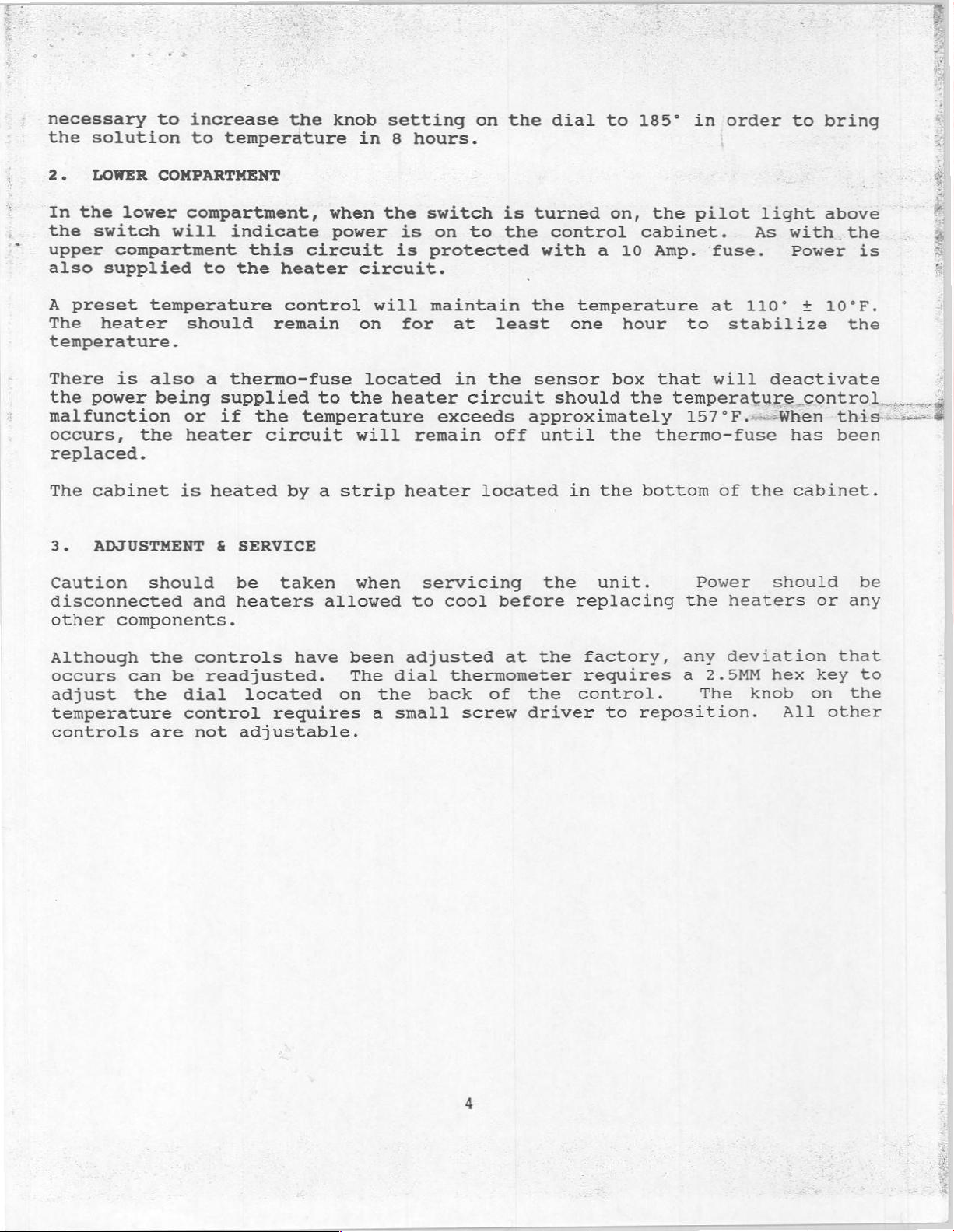
necessary
the
solution
to
increase
to
temperature
the
knob
in
setting
8
hours.
on
the
dial
to
185°
in
order
to
bring
2.
LOWER
In
the
lower
the
switch
upper
also
A
The
temperature.
There
the
compartment
supplied
preset
heater
is
power
malfunction
occurs,
replaced.
The
cabinet
3.
ADJUSTMENT
Caution
disconnected
other
components.
COMPARTMENT
compartment,
will
to
temperature
should
also
a
being
or
the
heater
is
heated
should
and
indicate
this
the
heater
control
remain
thermo-fuse
supplied
if
the
circuit
by a strip
£
SERVICE
be
taken
heaters
when
the
power
circuit
circuit.
will
on
located
to
the
heater
temperature
will
when
allowed
switch
is
on to
is
protected
maintain
for
exceeds
remain
heater
servicing
to
at
in
circuit
cool
is
turned
the
with
the
least
the
sensor
approximately
off
until
located
before
control
temperature
one
should
in
the
replacing
on,
a
10
hour
box
the
the
the
unit.
the
pilot
cabinet.
Amp.
to
that
temperature
157*F.-=-When
thermo-fuse
bottom
Power
the
fuse.
at
110°
stabilize
will
of
the
heaters
light above
As
with
Power
+
the
10°F.
the
deactivate
control...
this---=
has
been
cabinet.
should
or
any
is
be
$
È
i
Although
occurs
can
adjust
temperature
controls
the
the
are
controls
be
readjusted.
dial
control
not
have
located
requires
adjustable.
been
The
on
the
a
dial
small
adjusted
thermometer
back
screw
of
at
the
the
driver
factory,
requires
control.
to
reposition.
any
a
The
deviation
2.5MM
knob
hex
All
key
on
other
that
to
the
Page 7

Blickman
20-21
WAGARAW
CABINET,
SOLUTION
Health
RD.,
PO.
MAINTENANCE
CORROSION-
488,
FAIR
WARMING,
Industries,
LAWN,
N.J.
07410-0488/201-423-3660
MANUAL
TWO
RESISTANT
COMPARTMENT
Inc.
6530-01-207-0827
G530-01-a44-1976
MODEL
DLA120-89-C-8200
7924-SSDP
(I)
MM
MANUFACTURERS:
Health
Care
Equipment
and
Food
Conveyors
Page 8

TABLE
OF
CONTENTS
OPERATOR
MAINTENANCE
UPPER
LOWER
CONTROL
CONTROL
Figures
MAINTENANCE
TECHNICIAN
COMPARTMENT
COMPARTMENT
1
through
. . .
INSTRUCTIONS
.
.
5.. . -
ATES
Page 9
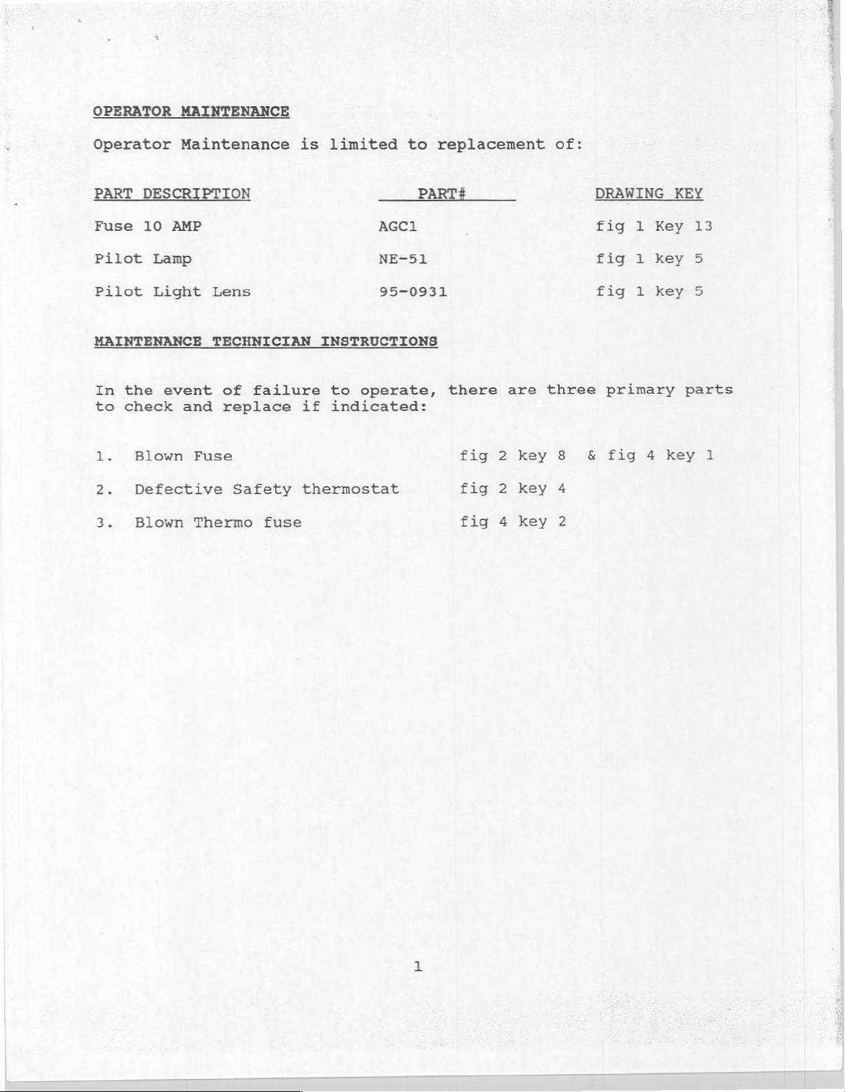
OPERATOR
MAINTENANCE
Operator
PART
Fuse
Pilot
Pilot Light
MAINTENANCE
In
the
to
check
1.
Blown
2.
Defective
3.
Blown
Maintenance
DESCRIPTION
10
AMP
Lamp
event
Lens
TECHNICIAN
and
Fuse
Thermo
of
failure
replace
Safety
fuse
is
limited
INSTRUCTIONS
to
operate,
if
indicated:
thermostat
to
PART#
AGC1
NE-51
95-0931
replacement
there
are
fig 2 key
fig
2
fig
4
key
key
of:
three
8
4
2
DRAWING
fig
fig
fig
primary
&
fig
1
1
1
Key
key
key
4
KEY
parts
key
13
5
5
1
Page 10
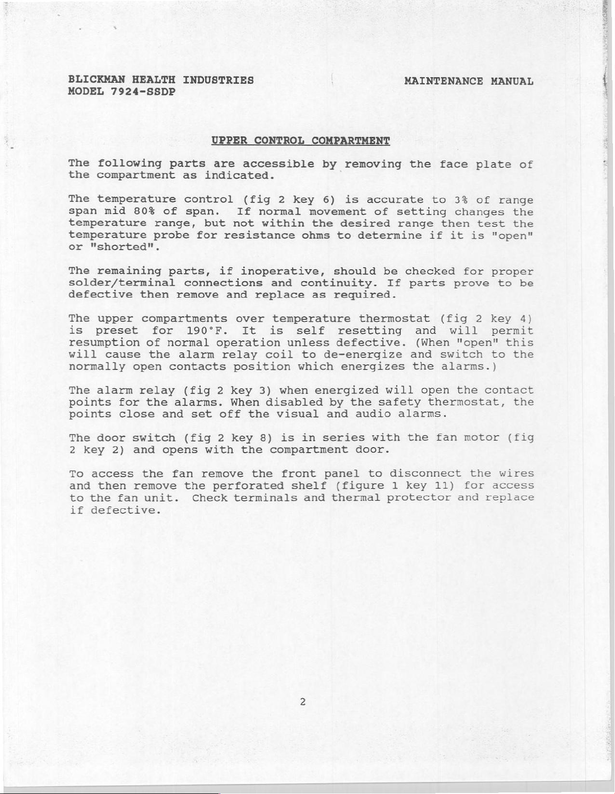
BLICKMAN
MODEL
HEALTH
7924-SSDP
INDUSTRIES
ЕВ
CONTRO:
TME
MAINTENANCE
MANUAL
|
The
following
the
compartment
The
temperature
span
temperature
temperature
or
The
solder/terminal
defective
The
is
resumption
will
normally
The
points
points
The
2
mid
"shorted".
remaining
upper
preset
cause
alarm
for
close
door
key
2)
80$
open
switch
and
parts
as
control
of
span.
range,
probe
parts,
connections
then
compartments
relay
for
of
the
the
remove
190°F.
normal
alarm
contacts
(fig
alarms.
and
set
(fig 2 key
opens
are
indicated.
but not
for
resistance
if
and
operation
relay
position
2
key
When
off the
with
accessible
(fig
If
inoperative,
over
It
2
normal
within
and
replace
temperature
is
coil
3)
when
disabled
visual
8)
is in
the
compartment
by
key
unless
6)
movement
the
ohms
continuity.
as
self
to
de-energize
which
energized
series
removing
is
desired
to
determine
should
required.
thermostat
resetting
defective.
energizes
by
the
and
audio
door.
accurate
of
setting
range
be
If
will
safety
alarms.
with
the
to
if
checked
parts
and
(When
and
the
open
thermostat,
the
fan
face
33
changes
then
it
is
for
prove
(fig
will
"open"
switch
alarms.)
the
motor
plate
of
range
test
"open"
proper
to
2
key
permit
to
contact
of
the
the
be
4)
this
the
the
(fig
To
access
and
then
to
the
if
defective.
fan
the
remove
unit.
fan
remove
the
Check
the
perforated
terminals
front
shelf
and
panel
(figure
thermal
to
disconnect
1
protector
key
11)
the
for
and
wires
access
replace
Page 11

BLICKMAN
MODEL
HEALTH
7924-SSDP
INDUSTRIES
MAINTENANCE
MANUAL
In
the
event
to
check
1.
Blown
2.
Defective
3.
Blown
The
remaining
solder/terminal
defective
The
for
normal
The
temperature
lower
110°F.
thermo-fuse
and
operation
operation
of
a
replace
fuse
thermostat
thermo
parts,
connections
then
compartment
and
remove
It
is
increase
the
LOWER
failure
fuse
self
unless
(fig
limiter
CONTROL
to
if
indicated:
if
inoperative,
and
safety
resetting
it
4
key
to
operate
and
replace
thermostat
is
defective.
2)
at
least
must
COMPARTMENT
there
Fig
Fig
Fig
should
continuity.
as
required.
and
is
designed
157°F.
be
replaced
4
4
4
will
key
key
key
(fig
are
to
if
three
1
3
2
be
checked
If
4
permit
fail
This
it
parts
key
is
has
primary
for
prove
3)
is
resumption
if
there
a
one
blown.
parts
proper
to
preset
is
time
be
of
a
The
compartment.
remainder
of
the
electrical
components
are
in
the
upper
Page 12

BLICKMAN
MODEL
HEALTH
7924-SSDP
INDUSTRIES
MAINTENANCE
MANUAL
Drawing
and
Wiring
Schematics
Figures
of
1
Model
through
7924-SSDP
5
Warming
Cabinet
Page 13

TELMINALS
OVER
E
Paris
TITAN
ZEM,
Déo
——
CONTROL
UPPER
=
LOWER
CONTROL
=
À
-一
CONTROL
reen
Cis
a
Doll
/
Arad
COVER
COMPARTMENT
トー
는
aise
COMPARTMENT
=
0044
RER,
>
meče
os
之
5
TEMP.
CONTROL - FENWALL
SAFETY
THERMOSTAT
THERMO + FUSE - FLMWONO
AUDIO
ALARM © MMLLOKY + SC
PILOT
LIGHT»
DIAL
THERMOMETER = CLIFTON
ALARM É VISUNL
FAN=ROTRON
RUOBER
CORD + CAROL
CAP.=PASI E SEYMOUR,
POWER
SWITCH * CUTLER
PRDT
LIGHT?
SUSSIMAN
WELLMAN
URE
CONTRIL
DIALIGHT
RELAY > POTTER
599-0150
SYLVANIA
te
Z
a
MEGON. + HKP.
THERIVIAL
«UNITED
54403655
4000
DOTO.
NO
CORP - 95.
66124-9
BRONIFIELO : KUSAIT
72 の FAN
CABLE
CORP.+
524la
HG
HAMMER
445:
>
|
|
|
=
=
Fle
A.
SYSTEMS * 35:
ELECTRIC
+102
/THÉLMO
SENSOR
INC. - 2512
9300
"15°-
DODRSW.
1613
$0,
n:
I5A-125V.;
ISGOK
5
x
UFPEK
över
smarcurs
peerornTEO,
bl
CONTROLS ~ E251,
1.132.
250°
ATH
COMPARTMENT,
2006
-_
D127
rr
saran
πο
272:
|
NOTE
к
CABINET
ACCEPT
RIGHT
“1925.
JAMES
DOORS
OR
124),
COUPLE + CT
LO20-
F.
VON
DOSH
LINE
CORO
・
få
2
LEFT
6055
IO
200
W-120
108-120N,
147
STD.
E
ASSEMBLY-
|
U
oy é TEME,
owe
En
Dook
LOWEK
COMPARTMENT
の
54- の 2737
PADDLE
20079
va
PRÉPAREO
FOR
THER
HANI
AMP
AGC
V. $ 955
19389
1304-
L190"
LCA-
LATEH
ise
Kr)
Ei
TO
1841,
-
43
1
=
E
B,
^
Power
carrai
er
η
に
ZON,
=
>
ke
WIRING
UPPER
Ug’
ΠΟΣΑ
v
dee
WIRING
LOWER
ab
ο
e+
FÅ
Е
COMPARTMENT
76.
06060
3
COMPARTMENT
FİG
MODEL
CABINET,
TWO
STAINLESS
NSN_
WAE
DATES).
nn
TE
KD
aaa
wag
DIAGRAM
2
00200
Fuse
core
DIAGRAN
N?
7924-5530P
SOLUTION
COMPARTMENT
STEEL
6530-01:
BLICKMAN
REVZA
HEALTH
FAIR
=>
2-5 | CKO,
12-26-89
sg
:
ue
208
ss
gra
| |
liğin
eer?
ei
5
$
|
MATO
[surtos
WARMING,
CONSTRUCTION
207-0927
INDUSTRIES,
LAWN,
NJ.
loner
BY
[FOLDER
7-24
owa
B-92485
o
INC,
フグ
 Loading...