

Blichmann Engineering 7 BBL, 5 BBL Insulated Hybrid Brewhouse Assembly Operation Maintenance Manual

7 BBL Insulated Hybrid Brewhouse
Assembly, Operation, & Maintenance
Congratulations on your purchase, and thank you for selecting the 7 BBL Hybrid
Brewhouse from Blichmann Engineering™. We are condent that it will provide you
years of service and many gallons of outstanding beer. This manual will familiarize
you with the use, assembly, and the sanitation procedures for the product.
IMPORTANT INFORMATION
PLEASE READ AND THOROUGHLY UNDERSTAND THIS MANUAL PRIOR TO USE
FOR IMPORTANT SAFETY INFORMATION!
WARNING:
CAUTION:
IMPORTANT:
IMPORTANT: Power demand for the brewhouse is 215A at 208V (three phase), 100A at 480V (three phase) or 310A at 240V (single phase).
Select a main breaker setting for 20% above the appropriate amperage to avoid nuisance tripping or as directed by your local codes.
Sections labeled “Warning” can lead to serious injury or death if not followed. Please thoroughly read these sections
and understand them completely before use. If you do not understand them or have any questions, contact your
retailer or Blichmann Engineering (www.BlichmannEngineering.com) before use.
Sections labeled “Caution” can lead to equipment damage or unsatisfactory performance of the equipment. Please
read these sections thoroughly. If you have any questions, contact your retailer or Blichmann Engineering
(www.BlichmannEngineering.com) before use.
Sections labeled “Important” should specically be followed to ensure satisfactory results with the product.
What’s In the Box?
Item Number Description Quantity
BEPS-BK-7BBL 7 BBL Boil Kettle 1
BEPS-HLT-7BBL 7 BBL Hot Liquor Tank 1
BEPS-MLT-7BBL 7 BBL Mash Tun with Mash Rake and Motor 1
Control Panel 1
Sanitary Heater Set of 3 2
BE-000861-00 2.5” Tri Clamp 3
BEPS-Pump-1HP 1HP Brewery Pump 2
BEPS-CHILLER-2.0SQM Heat Exchanger 1
BEPS-HoseKit-5 5 Hose Assembly Kit 1
BE-000957-00 CIP Spear 1.5” Tri Clamp 1
BE-000859-00 Cap 2.5” Sanitary 3
Item Number Description Quantity
BE-000868-00 Clamp Gasket 1.5” 17
BE-000633-00 1.5” Tri Clamp 17
BE-000863-00 Tri Clamp Elbow 1.5” 6
BE-001356-00 1.5” Multi Position Valve Tri Clamp 5
BE-001084-00 CIP Spray Ball 1
BE-001186-00 1.5” Sanitary Pipe 6” 1
BE-000630-00 Cap 1” & 1.5” Sanitary 2
BE-001479-00 6” Gasket 1
BE-000866-00 Clamp Gasket 2.5” 3
BE-001482-00 6” Tri Clamp Cap 1
BE-001478-00 6” Tri Clamp 1
7 BBL Insulated Hybrid Brewhouse V1 © Blichmann Engineering, LLC 2018
For replacement parts, visit: blichmannengineering.com/genuine-replacement-parts
1
Kettle Placement & Fitting Installation
Adjust the leveling feet as needed. It is recommended that you allow enough clearance between kettles and
also on the sides and rear to allow personnel access for cleaning and service of the ancillary equipment.
Although in practical use, the kettles can easily be slid out for any service needs.
Place heating elements (3) into the boil kettle and hot liquor tank. Secure with tri-clamps and gaskets.
Hose
Length (1.5 inch ID) Quantity
7 Feet 3
12 Feet 1
Construction:
Tube: FDA white EPDM (non oily transfer applications)
Reinforcement: Multiple plies of polyester tire cord with wire helix
Cover: Grey EPDM
Temperature Range: -40°F to +225°F
Not for continuous steam service
Stainless Steel 1.5 Inch Tri-Clamp ends
Note: that you can easily couple hoses together
with a clamp and gasket to make long runs to
fermentors etc.
Additional hoses can be purchased.
False Bottom
The false bottom will come pre-installed. To remove the false bottom, unscrew the bolt half way and pull the false bottom out. The false bottom will t
through the manway although it can be easier to pull out the top.
Brewery Ventilation
Ventilation needs for an electric brewhouse are fairly minimal as only the boil kettle needs to be ventilated. We recommend direct ventilation through
the 6 inch top port or a traditional commercial kitchen vent hood can be installed approximately 6.5 ft from the nished oor. General rules of thumb are
in the table below. It is recommended that you consult your local codes and consult with a professional prior to purchasing or installing your ventilation
equipment.
For recommendations on professional ventilations contact a Blichmann Engineering Pro Brewing representative.
Total power for the Boil Kettle is 36 KW.
Rules of Thumb Summary
Heat Load Factor 1 CFM per 100 BTU/hr (gas) or 34 CFM per KW (electric)
Hood Velocity Factor 50 CFM per ft2 of hood
Room Air Exchange Factor CFM = Room Volume (ft3) / 6 (you can generally disregard)
Hood Size Overhang 6” minimum front and sides
Hood Height 32” above kettles – approx. 6.5 ft from oor
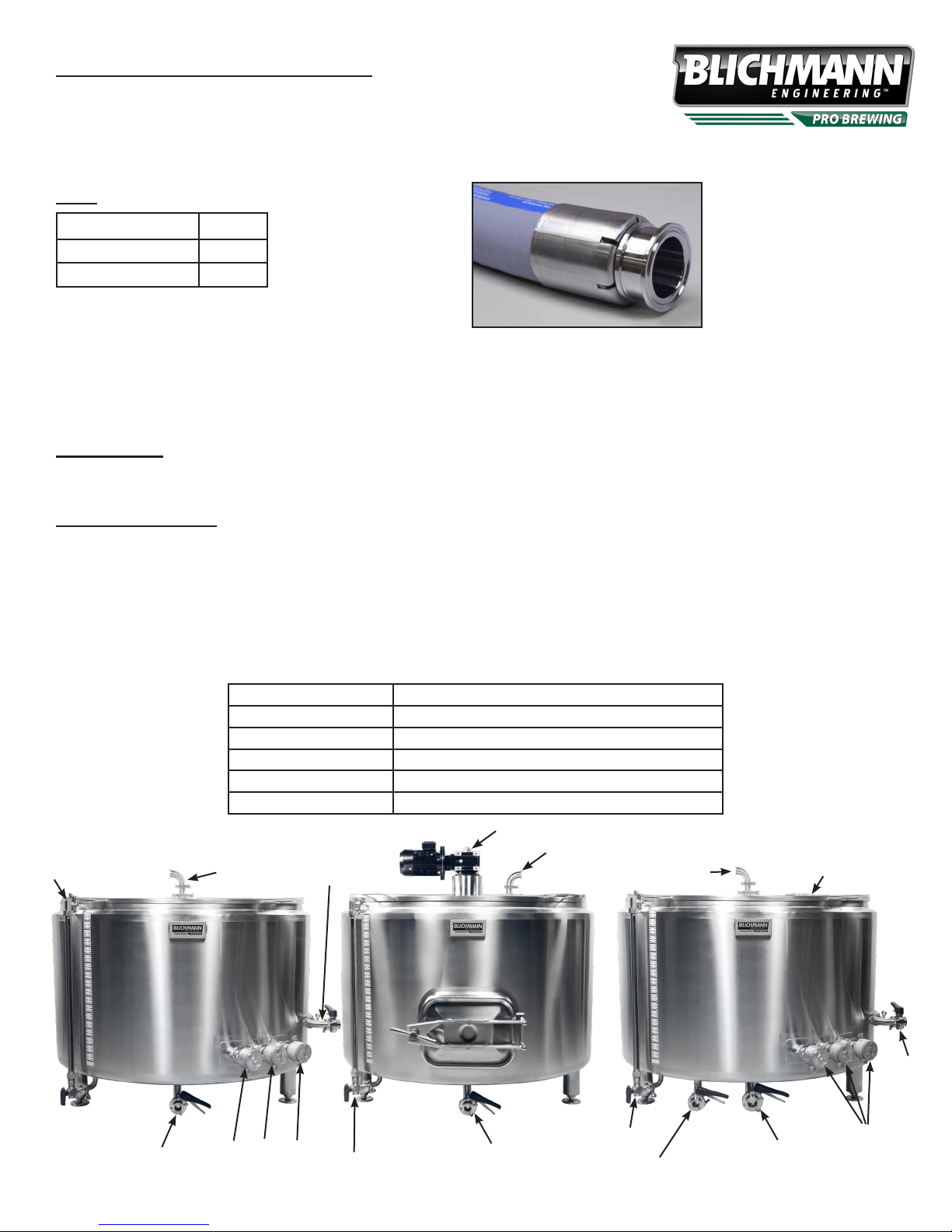
Gear Box
CIP / Vorlauf
Sight Glass
Hot Liquor Tank
CIP
Mash
Whirlpool
Boil Kettle
CIP
6” Exhaust Port
Whirlpool
Bottom Drain
7 BBL Insulated Hybrid Brewhouse V1 © Blichmann Engineering, LLC 2018
For replacement parts, visit: blichmannengineering.com/genuine-replacement-parts
Heating Element Ports
Sight Glass
Bottom Drain
Sight Glass
Clear Wort Draw Point
(Not used on HLT)
Bottom Drain
Heating Element Ports
2

CONTROL PANEL
7 BBL Insulated Hybrid Brewhouse V1 © Blichmann Engineering, LLC 2018
For replacement parts, visit: blichmannengineering.com/genuine-replacement-parts
3
THREE PHASE
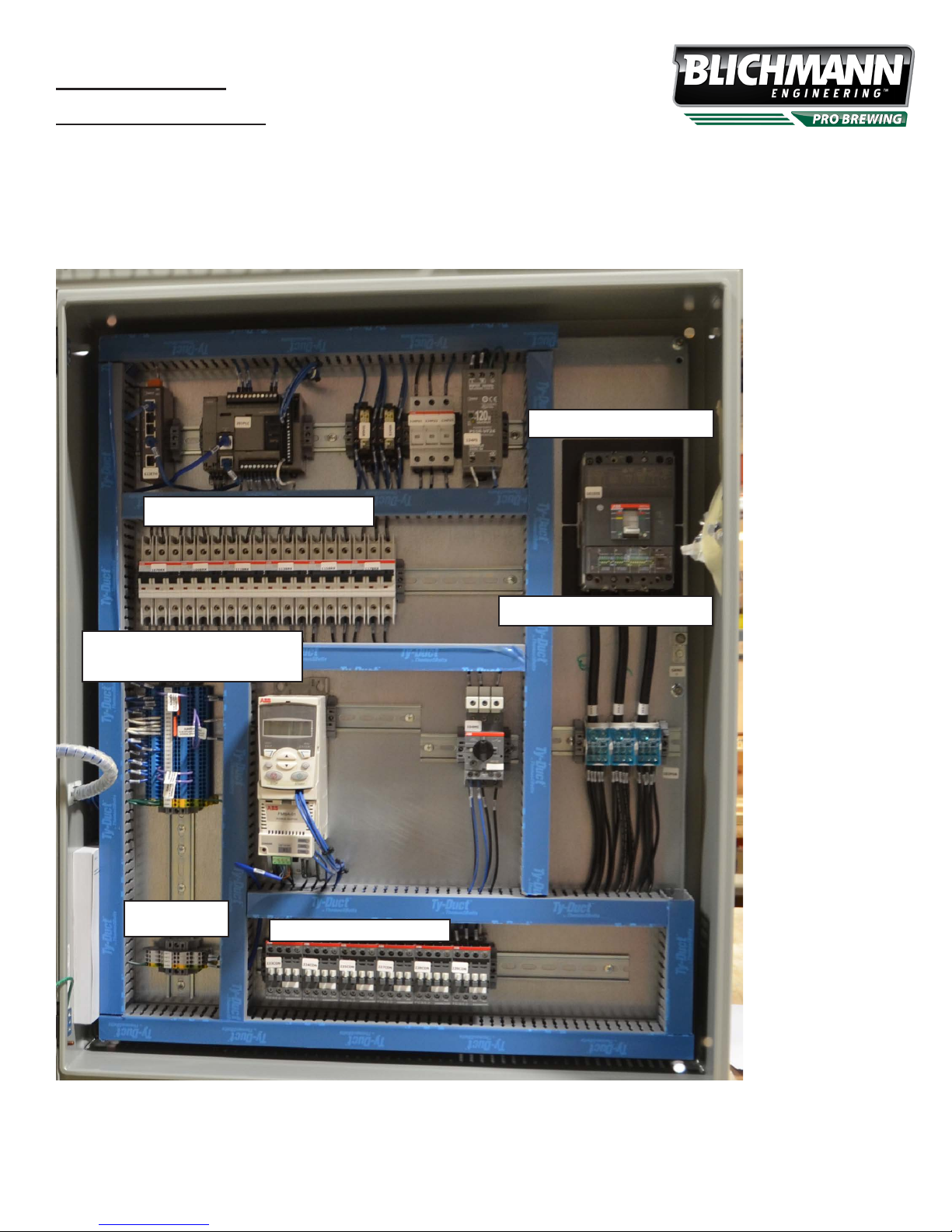
Control Panel Installation
Warning: Always follow ALL local codes and regulations for installation of this panel. We highly recommend hiring a certied electrician for this work!
This panel is designed for 208v or 230v three phase power only. (Single phase options are availible)
The back of the panel has 4 holes for afxing the panel to the wall of the brewhouse or onto a suitable stand. Mounting hardware or stand is not
included. The image below indicates the locations of the main components.
We recommend mounting the bottom of the panel 3 feet from the ground.
Panel Dimensions
36 inches tall
30 inches Wide
11 inches Deep
Main GFI Breaker
Heating Element Breakers
RTD and Low Level Float
Switch Terminal Block
Mash Paddle VFD
Terminal Block
Heating Element Contactors
DC Control Power Supply
Main Power GFI Breaker – This industrial grade GFI (ground fault interrupting) breaker is the connection point for main power cables connected to the
panel. Consult your local codes to determine if you can utilize this breaker as a main disconnect as well. In any case, we highly recommend a suitable
disconnect switch be installed prior to the panel for safe servicing of the panel. Your contractor will need to punch a hole in your panel for the main
power cable conduit in your desired location. Power demand for the brewhouse is 215A at 208V (three phase) or 100A at 480V (three phase). Select
a main breaker setting for 20% above the appropriate amperage to avoid nuisance tripping or as directed by your local codes.
7 BBL Insulated Hybrid Brewhouse V1 © Blichmann Engineering, LLC 2018
For replacement parts, visit: blichmannengineering.com/genuine-replacement-parts
4
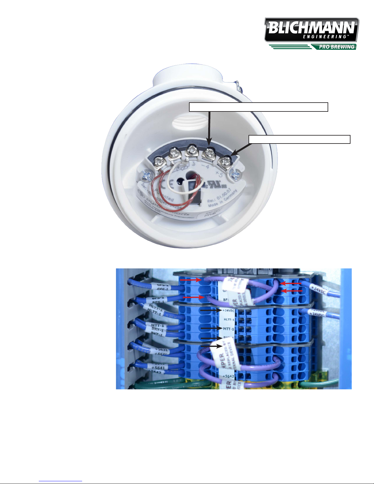
RTD’s – The brewhouse is equipped with two durable high precision 4-20mA RTD’s (resistance temperature
detectors). Wire the sensors to the control panel terminal block shown in the image. The wiring diagram in
the RTD junction box is also shown.
Important: Use shielded 2 conductor cable designed specically for wiring RTD’s for most accurate read-
ings. We recommend 18 gauge wire.
Connect to either HLTT-1, MTT-1, or BKT-1
Connect to +24VDC in panel
RTD and Low Level Float Switch Terminal Block
Boil Kettle
BKT-1 to -4
+24VDC to +5
Mash Tun
MTT-1 to -4
+24VDC to +5
HLT
HLTT-1 to -4
+24VDC to +5
Float Switch Wiring
Remove the purple jumper wire from BFS-1 and
+24VDC and wire in the low level oat switch for the
Boil Kettle.
Remove the purple jumper wire from GFS-1 and
+24VDC and wire in the low level oat switch for the
Hot Liquor Tank.
Heating Elements: The brewhouse is supplied with six 12,000 W ultra-low watt density heating elements. We recommend SJOOW type cable. Your
local codes will dictate the cable type and gauge.
IMPORTANT: Always consult your local codes to determine what type of cable is acceptable, what gauge is required, and maximum lengths of
exible cable allowed.
7 BBL Insulated Hybrid Brewhouse V1 © Blichmann Engineering, LLC 2018
For replacement parts, visit: blichmannengineering.com/genuine-replacement-parts
5

Float Switches – Float switches are provided to help prevent
unintended energizing of the heating elements. It is vital that the
heating elements be immersed in liquid prior to energizing them.
Failure to immerse the heating elements will cause them to fail and
potentially cause a re! Wire from the oat switch to the terminal
block shown in the panel above. Wire to terminal 1 and 2 on the
oat switch. Polarity is not important. Use suitable 2 wire cable (18
gauge recommended) for connection. If jumper wires are installed
in the panel remove them when you install the switch wires.
When wiring the oat switches to the control panel use a continuity
tester on the leads to ensure that the switch is open when in the
down (empty) position, and is closed (has continuity) in the up (full)
position. At that time wire to the panel.
Remove the rubber band on the low level oat switch.
The indent should be pointed up
for proper oat switch operation.
WARNING - DO NOT twist the oat
switch apart. This is NOT covered
under warranty.
CAUTION: The low water level switches are a backup to an unintended energizing of the heaters. They are NOT intended to
be normal shutoff switches and solely relied upon to keep the heaters from unintentionally
energizing! Dry-red heating elements are not covered under warranty!
Mash Paddle VFD Terminal Block
Wire three phase mash paddle motor
into the mash paddle VFD terminal block.
Connect wiring from 104T1 to U1, 104T2
to V1, 104T3 to W1 for power and GND
to the grounding screw for ground.
Mash Rake MotorMash Paddle VFD Terminal Block
7 BBL Insulated Hybrid Brewhouse V1 © Blichmann Engineering, LLC 2018
For replacement parts, visit: blichmannengineering.com/genuine-replacement-parts
6

Chillers: Sanitize the chiller by either pumping StarSan or similar copper friendly sanitizer through the chiller. Alternately the chiller may be submerged
(ttings up) into a pail of sanitizer. Drain the chiller after the recommended time with the ttings facing down. Connect the chiller per the instructions
on the nameplate.
Drain off the rst gallon or so of wort from the boil kettle to a waste drain to eject any solids in the piping and to ensure only clear wort ows through the
chiller, use the higher drain point to prevent plugging. Then divert the ow to the chiller. Adjust the wort ow and/or the cooling water ow to achieve
the desired wort temperature to your fermentor.
IMMEDIATELY after use back-ush the chiller with hot water to eject any solids and wort. IMMEDIATELY soak the chiller, with ttings up, in PBW or
other copper friendly cleaning agents for 30 min or pump through the chiller. Rinse with hot water and then soak in sanitizer. Allow to drain, with ttings
down, then store with the chiller horizontal. Following this procedure consistently will give you a very long service life for your chiller.
Pumps: The pumps included with the system MUST NOT run dry or the impeller bearing surface will be damaged! This is NOT covered under warranty. Ensure the hoses and pump head are lled with liquid before turning on the pump. If you hear a loud squeal stop the pump immediately!
Caution: NEVER restrict the inlet to the pump. Always place ow throttling valves on the OUTLET of the pump ONLY. Failure to do this will cause
cavitation in the pump possibly leading to failure of the impeller. If you hear any grumbling or grinding in the pump STOP IMMEDIATELY as this is
cavitation. Cavitation failures are NOT covered under warranty.
Installing the Mash Rake
Step 1: Dissasemble the two piece impeller shaft by
removing the cotter pin. Remove the threaded nuts
from the top of the impeller shaft.
Slide the shaft collar over the impeller shaft as shown
in Figure 1. Screw the mounting bolts into the divots
on the impeller shaft.
Impeller
Shaft Collar
Gear Box
Gear Box Mount
Motor
Two Piece Impeller Shaft
Step 2: Place the shaft into the kettle as shown in Figure 2.
Figure 2
Figure 1
Nuts and Bolts
Divot
7 BBL Insulated Hybrid Brewhouse V1 © Blichmann Engineering, LLC 2018
For replacement parts, visit: blichmannengineering.com/genuine-replacement-parts
7
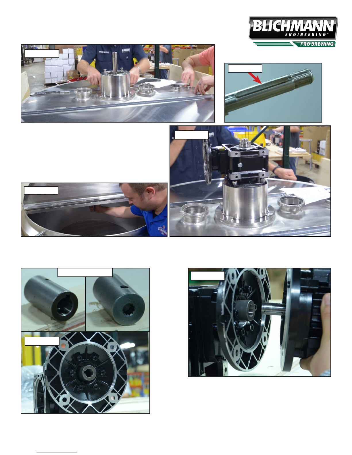
Step 3: Place the gear box mount over the end of the impeller shaft and secure the gear box with the four
bolts as shown in Figure 3.
Figure 3
Step 4: Remove the tape holding the key to the impeller shaft.
Figure 4a
Align the key with the groove in the gear box as you lower the gear
box onto the shaft. Use the 4 bolts to bolt the gear box to the gear box
mount shown in Figure 4a.
Lift the impeller shaft on the inside of the kettle and tighten the nuts
above the gear box. (Figure 4b)
Key
Figure 4b
Step 5: Place the star end of the gearbox adapter into the gear box as shown in Figure 5.
Align the motor shaft with the gear box adapter shown in Figure 6.
Gearbox Adapter
Figure 6
Figure 5
7 BBL Insulated Hybrid Brewhouse V1 © Blichmann Engineering, LLC 2018
For replacement parts, visit: blichmannengineering.com/genuine-replacement-parts
Step 7: Using the nuts and bolts provided, secure the gear box to the motor.
8

A. Limited Warranty
1. Blichmann Engineering warrants to the original purchaser that this product will be free from manufacturing defects in material and workmanship for a period of one (1) year
from the date of purchase by the customer. Proof of purchase is required. Blichmann Engineering’s obligation to repair or replace defective materials or workmanship is the
sole obligation of Blichmann Engineering under this limited warranty.
2. The limited warranty covers only those defects that arise as a result of normal use of the product and does not cover any other problems, including, but not limited to, those
that arise as a result of:
a. Improper maintenance or modication;
b. Damage due to incorrect voltage or improper wiring by customer;
c. Operation outside of the product’s specications;
d. Carelessness or neglect to operate the product in accordance with instructions provided with the product;
e. Damaging the tamper lab el on the product;
f. Damage by over-tightening the fasteners;
g. Failure to follow cleaning and / or maintenance procedures; or
h. Exceeding published operational temperatures.
3. Blichmann Engineering reserves the right to request delivery of the defective component for inspection before processing the warranty claim. If Blichmann Engineering
receives, during the applicable warranty period, notice of a defect in any component that is covered by the warranty, Blichmann Engineering shall either repair or replace the
defective component with a new or rebuilt component at Blichmann Engineering’s option.
4. Blichmann Engineering must be notified within seven (7) days of the delivery date of any shipping damage. Customer is responsible for shipping damage outside of this
time period. Approval for return must be provided by Blichmann Engineering prior to any return. Customer is responsible for keeping all original packaging material for
warranty returns. Blichmann Engineering is not responsible for damage from improperly packaged warranty returns, and these repair costs will be the sole responsibility of
the customer. Shipping costs for warranty returns are covered only for the contiguous United States.
5. Blichmann Engineering’s limited warranty is valid in any country where the product is distributed.
________________________________________
B. Limitations of Warranty
1. Any implied warranty that is found to arise by way of state or federal law, including any implied warranty of merchantability or any implied warranty of fitness, is limited in
duration to the terms of this limited warranty and is limited in scope of coverage to this warranty. Blichmann Engineering disclaims any express or implied warranty, including
any implied warranty of fitness for a particular purpose or merchantability, on items excluded from coverage as set forth in this limited warranty.
2. Blichmann Engineering makes no warranty of any nature beyond that contained in this limited warranty. No one has authority to enlarge, amend, or modify this limited
warranty, and Blichmann Engineering does not authorize anyone to create any other obligation for it regarding this product.
3. Blichmann Engineering is not responsible for any representation, promise, or warranty made by any independent dealer or other person beyond what is expressly stated in
this limited warranty. Any selling or servicing dealer is not Blichmann Engineering’s agent, but an independent entity.
________________________________________
C. Limitations of Liability
1. The remedies provided in this warranty are the customer’s sole and exclusive remedies.
2. Except for the obligations specifically set forth in this warranty, in no event shall Blichmann Engineering be liable for direct, indirect, special, incidental, or consequential
damages, whether based on contract, tort, or any other legal theory and whether or not advised of the possibility of such damages.
3. This warranty does not cover, and in no event shall Blichmann Engineering be liable for, travel, lodging, or any other expense incurred due to manufacturing defects in
material and workmanship, or any other reason.
4. Any performance of repairs after the warranty coverage period has expired or performance of repairs regarding anything excluded from coverage after this limited warranty
shall be considered good-will repairs and they will not alter the terms of this limited warranty, or extend any warranty coverage period.
5. Venue for any legal proceedings relating to or arising out of this warranty shall be in Tippecanoe County, Indiana, United States, which courts will have exclusive jurisdiction.
________________________________________
D. Local Law
1. This warranty gives the customer specific legal rights. The customer may also have other rights that vary from state to state in the United States or other countries.
2. To the extent that this warranty is inconsistent with local law, it shall be deemed modified, only to the extent necessary to be consistent with such local law.
Blichmann Engineering Product Warranty
7 BBL Insulated Hybrid Brewhouse V1 © Blichmann Engineering, LLC 2018
For replacement parts, visit: blichmannengineering.com/genuine-replacement-parts
9
 Loading...