

Page 1

BLEMO Frequenzumrichter
Frequency Inverter
ER21
user manual
Page 2

46
ENGLISH
IT NEUTRAL POINT CONNECTION : In the event of use on a 3-phase network with a voltage greater than
460V ±10 % with an isolated or high-impedance system (IT), the internal EMC filter capacitors which are
connected to ground must be disconnected. Consult BLEMO Frequenzumrichter product support who are
the only people qualified to perform this operation.
When the speed controller is powered up, the power elements and some of the control components are
connected to the line supply. It is extremely dangerous to touch them. The cover of the speed controller
must remain closed.
In general, the speed controller power supply must be disconnected before any operation on either the
electrical or mechanical parts of the installation or machine.
After the BLEMO-ER21 has been switched off and the red LED has gone out, wait for 10 minutes before
working on the equipment. This is the time required for the capacitors to discharge.
The motor can be stopped during operation by inhibiting start commands or the speed reference while the
speed controller remains powered up. If personnel safety requires prevention of sudden restarts, this
electronic locking system is not sufficient : fit a device to remove the power circuit.
The speed controller is fitted with safety devices which, in the event of a fault, can shut down the speed
controller and consequently the motor. The motor itself may be stopped by a mechanical blockage. Finally,
voltage variations, especially line supply failures, can also cause shutdowns.
If the cause of the shutdown disappears, there is a risk of restarting which may endanger certain machines
or installations, especially those which must conform to safety regulations.
In this case the user must take precautions against the possibility of restarts, in particular by using a low
speed detector to cut off power to the speed controller if the motor performs an unprogrammed shutdown.
The products and equipment described in this document may be changed or modified at any time, either
from a technical point of view or in the way they are operated. Their description can in no way be considered
contractual.
This speed controller must be installed and set up in accordance with IEC international standards and with
national standards. Bringing the device into conformity is the responsibility of the systems integrator who
must observe the European Union directives, especially the EMC directive.
The specifications contained in this document must be applied in order to comply with the essential
requirements of the EMC directive.
The BLEMO-ER21 must be considered as a component : it is neither a machine nor a device ready for use
in accordance with European directives (machinery directive and electromagnetic compatibility directive).
It is the responsibility of the end user to ensure that the machine meets these standards.
Page 3

49
ENGLISH
Table of Contents
Steps for Setting Up the Speed Controller _____________________________________________ 50
Factory Configuration _____________________________________________________________ 51
Speed Controller References _______________________________________________________ 52
Mounting _______________________________________________________________________ 54
Wiring _________________________________________________________________________ 57
Basic Functions__________________________________________________________________ 64
Configurable I/O Application Functions________________________________________________ 65
Setup - Preliminary Recommendations________________________________________________ 71
Programming ___________________________________________________________________ 72
Local control option_______________________________________________________________ 74
Remote Display Module Option _____________________________________________________ 75
Configuration____________________________________________________________________ 76
Settings________________________________________________________________________ 84
Maintenance ____________________________________________________________________ 89
Faults - Causes - Remedies ________________________________________________________ 90
Configuration/Settings Tables_______________________________________________________ 92
Page 4

50
ENGLISH
Steps for Setting Up the Speed Controller
1 - Delivery of the speed controller
• Check that the speed controller reference printed on the label is the same as that on the delivery note
corresponding to the purchase order.
• Remove the BLEMO-ER21 from its packaging and check that it has not been damaged in transit.
2 - Fit the speed controller and attach its labels (page 51)
3 - Connect the following to the speed controller :
• The line supply, ensuring that it is
volt free
• The motor, ensuring that the terminal configuration corresponds to the supply voltage
• The control via the logic inputs
• The speed reference via the logic or analog inputs
4 - Switch on the speed controller, but do not give a run command
5 - Configure :
• The nominal frequency (bFr) of the motor, if it is other than 50 Hz
• The parameters of the I/O menu, and drC menus but if the factory configuration of the speed controller
is not suitable for the application
6 - Set the following in the Set menu :
If the speed controller factory settings are not suitable :
• The acceleration (ACC) and deceleration (dEC) ramps
• The minimum (LSP) and maximum (HSP) speeds
• The motor thermal protection current (ItH)
• Other parameters as required, if the factory configuration has been changed
7 - Start the speed controller
Practical recommendations
• To help with programming the speed controller, fill in the configuration and settings tables (page 92),
in particular when the factory configuration has been changed.
• Programming the BLEMO-ER21 can be made easier by internal sequence selections and interlocks.
In order to gain the maximum benefit from this, it is recommended that the menus are accessed in the
following order :
1) - I/O 2) - drC 3) - Set
Not all steps are necessary in every case.
Caution : A check must be made to ensure that the functions which have been programmed
are compatible with the wiring layout used.
Page 5

51
ENGLISH
Factory Configuration
Factory settings
The BLEMO-ER21 is factory-set for the most common operating conditions:
- Display : speed controller ready (when stopped), motor frequency (when running)
- Line supply : 50 Hz.
- Motor voltage : 230 V or 400 V, depending on product
- Ramps : 3 seconds
- Low speed : 0 Hz
- High speed : 50 Hz.
- Frequency loop gain : standard
- Motor thermal current = nominal speed controller current
- Standstill injection braking current = 0.7 x nominal speed controller current, for 0.5 seconds
- Constant torque operation, with sensorless flux vector control
- Automatic adaptation of the deceleration ramp in the event of overvoltage on braking
- Switching frequency 4 kHz
- Logic inputs :
• LI1, LI2 : 2 directions of operation, 2-wire control
• LI3, LI4 : 4 preset speeds (0 Hz, 10 Hz, 15 Hz, 50 Hz)
- Analog inputs :
• AI1 (0 + 10 V) : speed reference
• AI2 (0 + 10 V) or AIC (0, 20 mA) : summing AI1
- Relay R2 :
• speed reference reached
- Analog output AO (0 - 20 mA) :
• motor frequency
If the above values are compatible with the application, the speed controller can be used without
changing the settings.
Labels
The speed controller is supplied with labels which are stored under the hinged cover :
• 1 label fixed inside the hinged cover : wiring diagram
• 3 self-adhesive labels to be fixed near the speed controller if required : programming of the
main parameters, meaning of the fault codes and customer settings (blank label).
Page 6
52
ENGLISH
Speed Controller References
Single phase supply voltage (1) U1...U2 : 200…240 V 50/60 Hz
3-phase supply voltage (1) U1...U2 : 200…230 V 50/60 Hz
3-phase supply voltage (1) U1...U2 : 380…500 V 50/60 Hz
Motor Line supply BLEMO-ER21-...-K
Power
indicated on
plate (2)
Line
current (3)
Max.
prosp.
line Isc
Line
current
Max.
transient
current (4)
Power
dissipated
at nominal
load
Reference
at U 1 at U 2
kW HP A A kA A A W
0.37 0.5 7.3 6.1 1 3.3 3.6 32
ER21-0.37K
0.75 1 9.8 8.2 1 4.8 6 45
ER21-0.75K
1.5 2 16 13.5 1 7.8 10.9 75
ER21-1.5K
2.2 3 22.1 18.6 1 11 15 107
ER21-2.2K
3 - 17.6 15.4 5 13.7 18.5 116
ER21-3.0K
4 5 21.9 19.1 5 17.5 24.6 160
ER21-4.0K
5.5 7.5 38 33.2 22 27.5 38 250
ER21-5.5K
7.5 10 43.5 36.6 22 33 49.5 343
ER21-7.5K
Motor Line supply BLEMO-ER21-...-K
Power
indicated on
plate (2)
Line
current (3)
Max.
prosp.
line Isc
Line
current
Max.
transient
current (4)
Power
dissipated
at nominal
load
Reference
at U 1 at U 2 at 380
to 460V
at 500V
kW HP A A kA A A A W
0.75 1 3.9 3.5 5 2.3 2.1 3.5 33
ER21-0.75/4K
1.5 2 6.5 5.7 5 4.1 3.8 6.2 61
ER21-1.5/4K
2.2 3 8.4 7.5 5 5.5 5.1 8.3 81
ER21-2.2/4K
3 - 10.3 9.1 5 7.1 6.5 10.6 100
ER21-3.0/4K
4 5 13 11.8 5 9.5 8.7 14.3 131
ER21-4.0/4K
5.5 7.5 22.1 20.4 22 14.3 13.2 21.5 215
ER21-5.5/4K
7.5 10 25.8 23.7 22 17 15.6 25.5 281
ER21-7.5/4K
11 15 39.3 35.9 22 27.7 25.5 41.6 401
ER21-11.0/4K
15 20 45 40.8 22 33 30.4 49.5 543
ER21-15.0/4K
Page 7

53
ENGLISH
Speed Controller References
(1) Nominal supply voltages : min. U1, max. U2.
(2) These power ratings are for a maximum switching frequency of 4 kHz, in continuous operation. The
switching frequency is adjustable from 2 to 15 kHz.
Above 4 kHz derate the nominal speed controller current. The nominal motor current should not exceed
this value :
• Up to 12 kHz derate by 10%
• Above 12 kHz derate by 20%.
(3) Typical value for a 4-pole motor and a maximum switching frequency of 4 kHz, with no additional line
choke.
(4) For 60 seconds.
Page 8

54
ENGLISH
Mounting
Dimensions and weights
Mounting recommendations
Install the unit vertically, at ± 10°.
Do not place it close to heating elements.
Leave sufficient free space to ensure that the air required for cooling purposes can circulate from the
bottom to the top of the unit.
BLEMO-ER21-...-K
ammbmmcmmGmmHmm2 Ømm4 Ømmweight
kg
-0.37K, -0.75K
105 130 140 93 118 5 1.8
-1.5K, -0.75/4K, -1.5/4K
130 150 150 118 138 5 2.5
-2.2K, -3.0K, -4.0K, -2.2/4K, -3.0/4K, -4.0/4K
140 195 163 126 182 5 3.8
-5.5K, -7.5K, -5.5/4K, -7.5/4K
200 270 170 180 255 6 6.1
-11.0/4K, -15.0/4K
245 330 195 225 315 6 9.6
Page 9

55
ENGLISH
Mounting
Mounting and Temperature Conditions
Free space in front of the unit : 10 mm minimum.
• from -10°C to 40°C :
• d >= 50 mm : no special precautions.
• d = 0 (speed controllers mounted side by side) : remove the protective cover from
the top of the speed controller, as shown below (the degree of protection becomes
IP20).
• from 40°C to 50°C :• d >= 50 mm : remove the prot ective cover from the top of the speed controller, as
shown below (the degree of protection becomes IP20). If the cover is left on, derate
the nominal speed controller currentnominal speed controller current by 2.2 % for
every °C above 40°C.
• d = 0 : remove the protective cover from the top of the speed controller, as shown
below (the degree of protection becomes IP20), and derate the nominal speed
controller current by 2.2 % for every °C above 40°C .
• from 50°C to 60°C :• d >= 50 mm : remove the prot ective cover from the top of the speed controller, as
shown below (the degree of protection becomes IP20), and derate the nominal
speed controller current by 3 % for every °C above 50°C.
Page 10

56
ENGLISH
Mounting
Electromagnetic compatibility
EMC plate supplied with the speed controller
Fit the EMC plate used for equipotential earthing on the holes of the
BLEMO-ER21 heatsink using the 2 screws provided, as shown in
the drawing opposite.
BLEMO-ER21-...-K ∆bmmØ
mm
-0.37K, -0.75K, -1.5K,
-2.2K, -3.0K, -4.0K,
-0.75/4K, -1.5/4K, -2.2/4K,
-3.0/4K, -4.0/4K
48 4
-5.5K, -7.5K,
-5.5/4K, -7.5/4K, -11.0/4K,
-15.0/4K
79 4
4 Ø screws for fixing
EMC clamps
Page 11
57
ENGLISH
Wiring
Access to terminals
To access the terminals, undo the screws on the cover and tilt.
Diagram : Example showing ER21-0.37K
The speed controllers have a
removable plastic cable gland
with knock-outs for running
cables through, if required
(control and braking resistor).
1
- Control
2
- Power (1 or 2 terminals depending on the rating)
3
- Ground screw for motor cable (on low ratings only)
Power terminals
Specifications of power terminals
BLEMO-ER21-...-K Maximum connection capacity Tightening torque in Nm
AWG mm
2
-0.37K, -0.75K AWG 14 2.5 0.8
-1.5K, -0.75/4K, -1.5/4K AWG 12 3 1.2
-2.2K, -3.0K, -4.0K,
-2.2/4K, -3.0/4K, -4.0/4K
AWG 10 5 1.2
-5.5K, -7.5K,
-5.5/4K, -7.5/4K
AWG 5 16 2.5
-11.0/4K, -15.0/4K AWG 3 25 4.5
Page 12
58
ENGLISH
Wiring
Functions of power terminals
Arrangement of the power terminals
Do not remove the connector linking terminals P0 and PA.
Terminal Function For BLEMO-ER21-...-K
BLEMO-ER21 ground terminal All ratings
L1
L2 Supply for power terminals
All ratings
L3 3-phase only
PO DC bus + polarity All ratings
PA Output to braking resistor All ratings
PB Output to braking resistor All ratings
PC DC bus - polarity All ratings
U
V
W
Output to motor All ratings
BLEMO-ER21 ground terminal -5.5K, -7.5K, -5.5/4K, -7.5/4K,
-11.0/4K, -15.0/4K
ER21-0.37K, -0.75K, -1.5K, -2.2K :
ER21-3.0K, -4.0K, -0.75/4K, -1.5/4K, -2.2/4K, -3.0/4K, -4.0/4K :
ER21-5.5K, -7.5K, -5.5/4K, -7.5/4K, -11.0/4K, -15.0/4K :
For the motor ground, use the ground screw
provided on the heatsink or on the EMC plate.
For the motor ground, use the ground screw
provided on the heatsink or on the EMC plate.
Page 13
59
ENGLISH
Wiring
Control terminals
Arrangement, specifications and functions of the control terminals
Terminal
Function
Electrical specifications
R1A
R1B
R1C
Common point C/O contact
(R1C) of R1 fault relay
Min. switching capacity
• 10 mA for 5 V
=
Max. switching capacity on inductive load
(cos
ϕ
= 0.4 and L/R = 7 ms) :
• 1.5 A for 250 V
~
and 30 V=
R2A
R2C
N/O contact of R2
programmable relay
COM I/O common
AI1 Analog voltage input Analog input 0 + 10 V
• impedance 30 k
Ω
• resolution 0.01 V
• precision ± 4.3%, linearity ± 0.2%, of max. value
• Sampling time 4 ms max.
+10 Power supply for potentiometer
1 to 10 k
Ω
+10 V (+ 8 % - 0), 10 mA max, protected against short-circuits and
overloads
AI2
AIC
Analog voltage input
or
Analog current input
AI2 or AIC are assignable.
Use either, but not both.
Analog input 0 + 10 V, impedance 30 k
Ω
or
Analog input X - Y mA. X and Y can be programmed from 0 to 20 mA,
impedance 450
Ω
Resolution, precision, and sampling time of AI2 or AIC = AI1.
AO Analog output Output can be programmed for 0 - 20 mA or 4 - 20 mA
• Precision ± 6% of the max. value, max. load impedance 800
Ω
.
LI1
LI2
LI3
LI4
Logic inputs Programmable logic inputs
• + 24 V power supply (max. 30 V)
• Impedance 3.5 k
Ω
• State 0 if < 5 V, state 1 if > 11 V
• Sampling time 4 ms max.
+ 24 Logic input power
supply
+ 24 V protected against short-circuits and overloads, min. 19 V, max.
30 V. Max. customer current available 100 mA
- Maximum connection capacity
1.5 mm
2
- AWG 16
- Max. tightening torque :
0.5 Nm
Page 14

60
ENGLISH
Wiring
Wiring diagram for factory settings
(1) Line choke, if used (single phase or 3-phase).
(2) Safety relay contacts, for remote indication of the speed controller status.
(3) Internal +24 V. If an external +24 V source is used, connect the 0 V from that source to the COM
terminal, and do not use the + 24 terminal on the speed controller.
Note :
Fit interference suppressors to all inductive circuits near the speed controller or coupled to the
same circuit (relays, contactors, solenoid valves, etc)
Choice of associated components :
See BLEMO-ER21 catalog.
Page 15

61
ENGLISH
Wiring
Wiring recommendations
Power
Observe the cable cross-sectional areas recommended in the standards.
The speed controller must be earthed, in order to comply with regulations concerning high leakage
currents (over 3.5 mA). When the use of an upstream "residual current device" for protection is required
by the installation standards, a "type B" device must be used, which will operate even in the presence of
DC components. If the installation has several speed controllers on the same line, each controller must
be earthed separately. If necessary, fit a line choke (consult the catalogue).
Keep the power cables separate from circuits in the installation with low level signals (detectors, PLCs,
measuring apparatus, video, telephone).
Control
Keep the control circuits and the power cables apart. For control and speed reference circuits, we
recommend using shielded twisted cables with a pitch of between 25 and 50 mm, connecting the
shielding to ground at each end.
Page 16

62
ENGLISH
Wiring
Electromagnetic compatibility
Principle
• Grounds between speed controller, motor and cable shielding should have "high frequency"
equipotentiality.
• Use shielded cables with shielding connected to ground at 360° at both ends for the motor cable,
braking resistor (if used) and control-command cables. Conduit or metal ducting can be used for part of
the shielding length, provided that there is no break in continuity.
• Ensure maximum separation between the power supply cable (line supply) and the motor cable.
Installation diagram
Page 17

63
ENGLISH
Wiring
1 - Sheet steel grounded casing supplied with the speed controller, to be fitted as indicated on the
diagram.
2 - BLEMO-ER21
3 - Non-shielded power supply wires or cables.
4 - Non-shielded wires for the output of the safety relay contacts.
5 - Attachment and connection to ground of the shielding of cables 6, 7 and 8 as close as possible to the
speed controller :
- strip the shielding
- use cable clamps of an appropriate size on the parts from which the shielding has been stripped, to
attach them to the casing 1.
The shielding must be clamped onto the casing sufficiently tightly to create a good contact.
- types of clamp : stainless steel.
6 - Shielded cable for connecting the motor, with shielding connected to ground at both ends.
This shielding must be unbroken, and if there are intermediate terminals, they must be in EMC
shielded metal boxes.
7 - Shielded cable for connecting the control.
For applications which require a large number of conductors, small cross-sections must be used
(0.5 mm
2
).
The shielding must be connected to ground at both ends. This shielding must be unbroken, and if
there are intermediate terminals, they must be in EMC shielded metal boxes.
8 - Shielded cable for connecting the braking resistor, if used. The shielding must be connected to
ground at both ends. This shielding must be unbroken, and if there are intermediate terminals, they
must be in EMC shielded metal boxes.
9 - Ground screw for the motor cable with low ratings, as the screw on the heatsink is inaccessible.
Note :
• If an additional input filter is used, it is mounted on the speed controller, and connected directly to the
line supply by an unshielded cable. Connection 3 on the speed controller is then made using the filter
output cable.
• Although there is an HF equipotential ground connection between the speed controller, the motor and
the cable shielding, it is still necessary to connect the PE protective conductors (green-yellow) to the
appropriate terminals on each of the devices.
Page 18

64
ENGLISH
Basic Functions
Fault relay, unlocking
The fault relay is energized when the speed controller is powered up and there is no fault. It has a
common point C/O contact.
The speed controller is unlocked after a fault by the following operations :
- Powering down the speed controller until the display and the red LED extinguish, then powering up
again
- Automatically when the "automatic restart" function has been activated
- Via a logic input when this input is assigned to the "fault reset" function
Speed controller thermal protection
Functions :
Thermal protection by thermistor fitted on the heatsink or integrated in the power module.
Indirect protection of the speed controller against overloads by current limit. Typical tripping points :
- motor current = 185 % of nominal speed controller current : 2 seconds
- motor current = maximum speed controller transient current : 60 seconds.
Speed controller ventilation
The fan is powered automatically when the speed controller is unlocked (operating direction +
reference). It is powered down a few seconds after the speed controller is locked (motor speed < 0.5 Hz
and injection braking completed).
Motor thermal protection
Function :
Thermal protection by calculating I2t
Caution : The motor thermal state memory is reset to zero when the speed controller is switched off.
Page 19

65
ENGLISH
Configurable I/O Application Functions
Logic input application functions
Direction of operation : forward / reverse
Reverse operation can be disabled for applications with a single direction of motor rotation.
2-wire control :
Run (forward or reverse) and stop are controlled by the same logic input, for which state 1 (run) or 0
(stop) is taken into account.
On power-up or a manual fault reset or after a stop command, the motor can only be powered once the
"forward", "reverse" and "DC injection stop" commands have been reset. If the automatic restart function
is configured (parameter Atr in the drC menu), these commands are taken into account without a reset
being necessary.
3-wire control :
Run (forward or reverse) and stop are controlled by 2 different logic inputs.
LI1 is always assigned to the stop function. Stop occurs on opening (state 0).
The pulse on the run input is memorized until the stop input is opened.
On power-up or a manual fault reset or after a stop command, the motor can only be powered once the
"forward", "reverse" and "DC injection stop" commands have been reset.
Ramp switching :
1st ramp : ACC, DEC ; 2nd ramp : AC2, DE2
This can be activated in 2 ways :
- By activating a logic input LIx or by detection of an adjustable frequency threshold Frt.
Step by step operation (JOG):
Low speed operation pulse
If the JOG contact is closed, then the operating direction contact activated, the ramp is 0.1 s whatever
the ACC, dEC, AC2 and dE2 settings. If the operating direction contact is closed, then the JOG contact
activated, the configured ramps are used.
The minimum time between 2 JOG operations is 0.5 seconds
Parameter which can be accessed in the adjust menu :
- JOG speed
Page 20
66
ENGLISH
Configurable I/O Application Functions
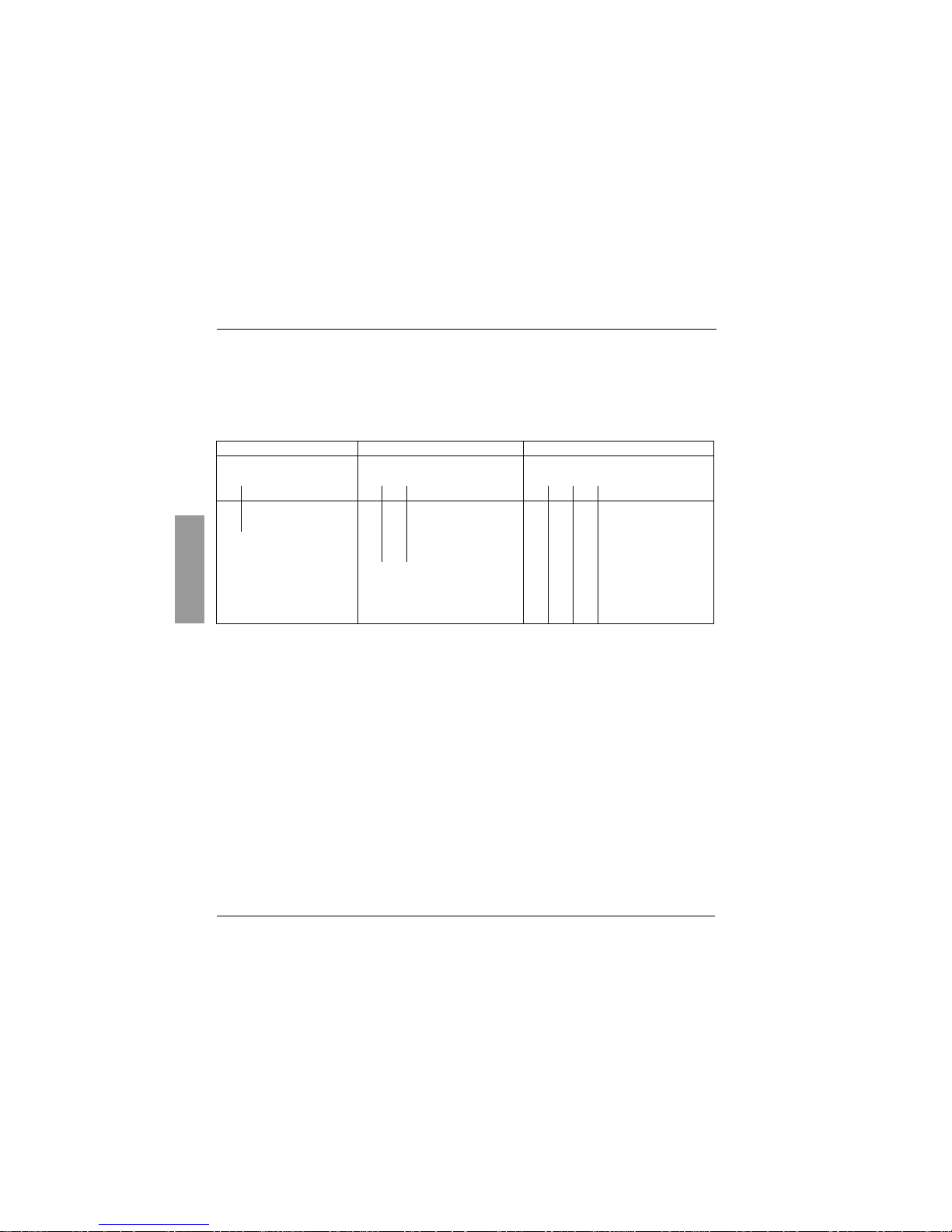
Preset speeds
2, 4 or 8 speeds can be preset, and requiring 1, 2, or 3 logic inputs respectively.
The following assignment order must be observed : PS2 (LIx), then PS4 (LIy), then PS8 (LIz).
To unassign the logic inputs, the following order must be observed : PS8 (LIz), then PS4 (LIy), then PS2
(LIx).
Reference switching :
Two references are switched (AI1 reference and AI2 or AIC reference) by a command on a logic input.
This function automatically assigns AI2 or AIC to speed reference 2
Connection diagram
Contact open, reference = AI2 or AIC
Contact closed, reference = AI1
If AI2/AIC is assigned to the PI function, operation combines
both functions, (see page 68)
2 preset speeds 4 preset speeds 8 preset speeds
Assign : LIx to PS2 Assign : LIx to PS2, then LIy to PS4 Assign : LIx to PS2, then
LIy to PS4, then LIz to PS8
LIx speed reference LIy LIx speed reference LIz LIy LIx speed reference
0 Reference (min = LSP) 0 0 Reference (min = LSP) 0 0 0 Reference (min = LSP)
1 HSP 0 1 SP2 0 0 1 SP2
1 0 SP3 0 1 0 SP3
1 1 HSP 0 1 1 SP4
1 0 0 SP5
1 0 1 SP6
1 1 0 SP7
1 1 1 HSP
Page 21

67
ENGLISH
Configurable I/O Application Functions
Freewheel stop
Stops the motor by the resistive torque only. The motor power supply is cut.
Freewheel stop occurs when the logic input assigned to this function opens (state 0).
DC injection stop
This can be activated in 2 ways :
- by activation of a logic input assigned to this function (state 1)
- automatically if the frequency is below 0.5 Hz
Fast stop :
Braked stop with the current deceleration ramp time divided by 4 within the limits of the braking
possibilities.
Fast stop occurs when the logic input assigned to this function opens (state 0).
Fault reset :
Clears the memorized fault and resets the speed controller if the cause of the fault has disappeared,
except for OCF (overcurrent), SCF (motor short-circuit), EEF and InF (internal faults) faults, which
require the controller to be powered down.
The fault is cleared when the logic input assigned to this function changes from 0 to 1.
Forced local mode when using the serial link :
Changes from line control mode (serial link) to local mode (control via the terminal block).
Page 22

68
ENGLISH
Configurable I/O Application Functions
Analog input application functions
Input AI1 is always the reference.
Assignment of AI2/AIC
(AI2 = 0, +10 V or AIC = X-Y mA, X and Y can be configured from 0 to
20mA)
Summing speed reference :
The frequency reference from AI2/AIC can be summed with AI1.
PI regulator :
Can be assigned to AI2/AIC. Allows a sensor to be connected and activates the PI
regulator.
The reference is input AI1 or an internal reference rPI which can be adjusted via the BLEMO-ER21
keypad.
Parameters which can be accessed in the adjust menu :
- regulator proportional gain (rPG)
- regulator integral gain (rIG)
- PI feedback multiplication coefficient (FbS) : is used to adjust the max. value of the feedback so that
it corresponds to the max. value of the PI regulator reference.
- reversal of the direction of correction (PIC) : if PIC = no, the motor speed increases when the error is
positive, if PIC = YES, the motor speed decreases when the error is positive.
"Manual - Automatic" operation with PI
This function combines the PI regulator and reference switching by a logic input. The speed reference
is given by AI1 or by the PI function, depending on the state of the logic input.
Page 23

69
ENGLISH
Configurable I/O Application Functions
R2 relay application functions
Frequency threshold reached (FtA) :
The relay contact is closed if the motor frequency is greater than or
equal to the frequency threshold set by Ftd in the adjust menu.
Speed reference reached (SrA) :
The relay contact is closed if the motor frequency is greater than or equal
to the speed reference value.
Current threshold reached (CtA) :
The relay contact is closed if the motor current is greater than or equal
to the current threshold set by Ctd in the adjust menu.
Thermal state reached (tSA) :
The relay contact is closed if the motor thermal state is greater than or equal
to the thermal state threshold set by ttd in the adjust menu.
Analog output AO application functions
Analog output AO is a current output, which can be configured for 0 - 20 mA or 4 - 20 mA.
Motor current (code OCr) :
supplies the image of the motor rms current.
20 mA corresponds to twice the nominal motor thermal current Ith.
Motor frequency (code rFr) :
supplies the motor frequency calculated by the speed controller.
20 mA corresponds to the maximum frequency (parameter tFr).
Motor torque (code OLO) :
supplies the image of the motor torque as an absolute value.
20 mA corresponds to twice the nominal motor torque (typical value).
Power (code OPr)
: supplies the image of the power supplied to the motor by the speed controller.
20 mA corresponds to twice the nominal speed controller power.
Page 24
70
ENGLISH
Configurable I/O Application Functions
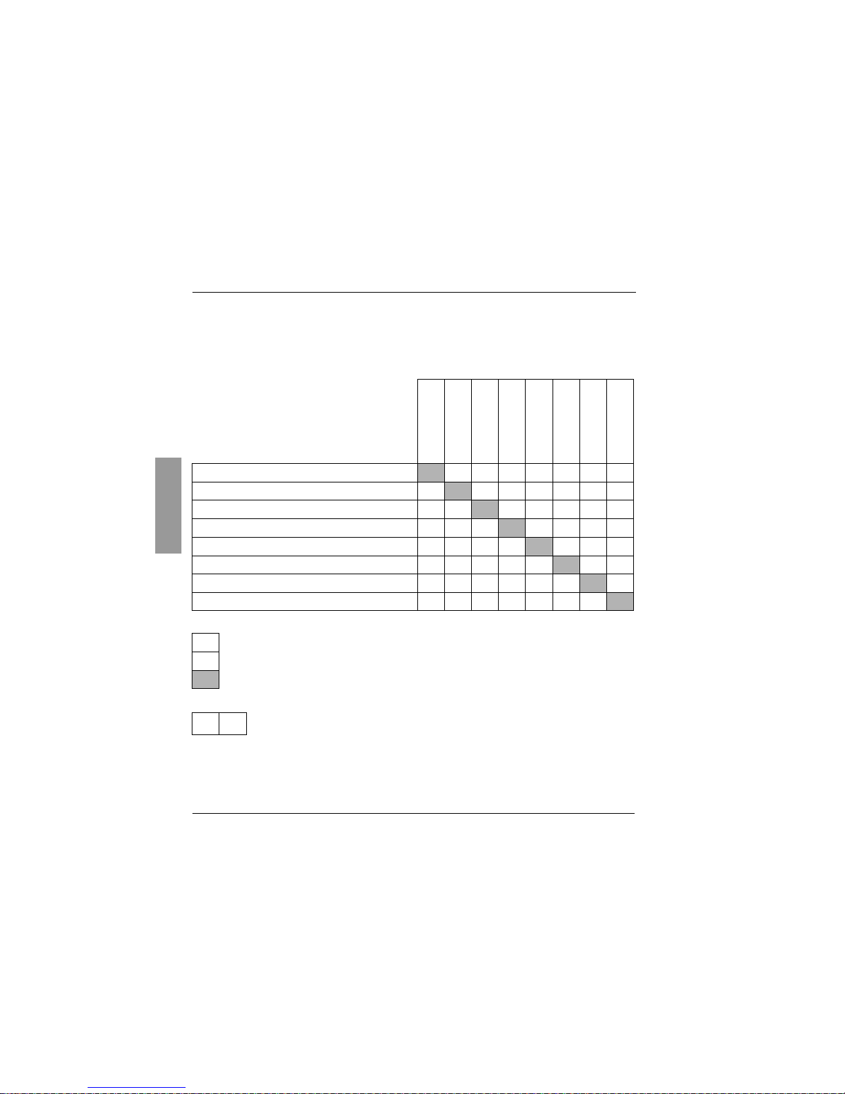
Function compatibility table
The choice of application functions may be limited by the number of I/O and by the fact that some
functions are incompatible with one another. Functions which are not listed in this table are fully
compatible.
Priority functions (functions which cannot be active at the same time) :
Stop functions take priority over run commands.
Speed references via logic command take priority over analog references.
DC injection
braking
Summing input
PI regulator
Reference switching
Freewheel stop
Fast stop
JOG operation
Preset speeds
DC injection braking
Summing input
n n
PI regulator
n n n
Reference switching
n n
Freewheel stop
Fast stop
JOG operation
n
Preset speeds
n n
n
Incompatible functions
Compatible functions
N/A
The function marked with the arrow takes priority over the other.
Page 25

71
ENGLISH
Setup - Preliminary Recommendations
Prior to powering up and configuring the speed controller
- Power down the logic inputs (state 0) to prevent any accidental startup. Otherwise,
an input assigned to the run command may cause the motor to start immediately when
exiting the configuration menus.
In power switching via line contactor
- Avoid operating contactor KM1 frequently (premature ageing of the filter capacitors).
Use inputs LI1 to LI4 to control the speed controller.
- These instructions are vital for cycles < 60 s, otherwise the load resistor may be
damaged.
User adjustment and extension of functions
If necessary, the display and the buttons can be used to modify the settings and to extend the functions
described in the following pages. It is very easy to return to the factory settings.
There are three types of parameter :
- display : values displayed by the speed controller
- adjustment : can be changed during operation or when stopped
- configuration : can only be modified when stopped and no braking is taking place. Can be displayed
during operation.
Check that changes to the current operating settings do not present any danger.
Changes should preferably be made with the speed controller stopped.
Page 26
72
ENGLISH
Programming
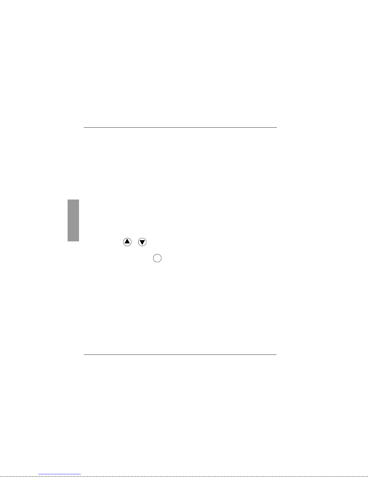
Functions of the keys and the display
Pressing or does not store the choices.
Store, save the displayed choice :
The display flashes when a value is stored.
Normal display, with no fault present and no startup :
- Init : Initialization sequence.
- rdY : Speed controller ready
- 43.0 : Display of the frequency reference
- dcb : DC injection braking in progress
- rtrY : Automatic restart in progress
- nSt : Freewheel stop command
- FSt : Fast stop command
• Red LED : powered up
(DC bus voltage)
• 4 seven-segment displays
• Enters a menu or a
parameter, or saves the
displayed parameter or
value
• Returns to the previous
menu or parameter, or
increases the displayed
value
• Exits a menu or parameter, or aborts the
displayed value to return to the previous value
in the memory
ENT
Page 27
73
ENGLISH
Programming
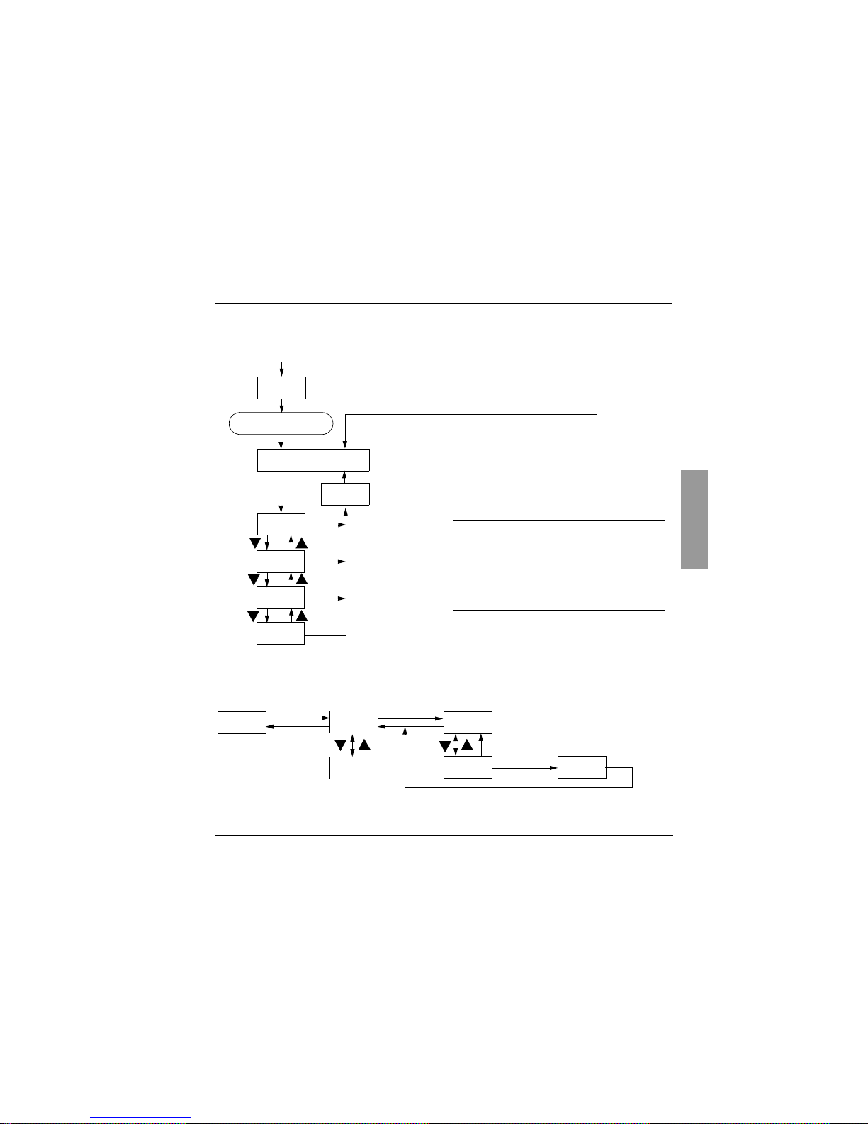
Access to menus
Access to parameters
Example :
(1) Configure bFr at the 1
st
power-up, using the same procedure as for the other parameters, as
described above.
Caution
, bFr can only then be modified after a return to "factory settings".
Subsequent power ups
1st power-up after factory configuration
Display of speed controller status
Drive
I/O
Nominal motor frequency :
50 Hz (factory setting) or 60 Hz
-bFr
rdY
---- -
SEt-
drC-
SUP-
ENT
ENT
bFR configuration (1)
ENT
ESC
ESC
ESC
ESC
I-0-
Settings
Display
Wait 3 seconds
If it is not possible to access the " SEt-", "drC-"
or "I-O-" menus, the speed controller is
protected by an access code. A remote display
module option or PC software is necessary to
access these menus, together with knowledge
of the code.
See SUP- menu page 87.
SEt-
ESC
-YYY
Menu
-UUU
100
101
101
ESC
ENT ENT
ENT
ESC
Parameter Value or assignment
Next parameter
1 flash
(save)
ESC
Page 28

74
ENGLISH
Local control option
This option consists of a reference potentiometer and provides access to 2 additional buttons on the
speed controller (see documentation provided with the option) :
– RUN button : controls the switching on of the motor. The direction of operation is determined by
parameter rOt in the settings menu SEt-.
– STOP/RESET button : controls the stopping of the motor and the clearing (resetting) of any
faults The first press on the button stops the motor, and if DC injection standstill braking
is configured, a second press stops this braking.
The reference given by the reference potentiometer is summed with analog input AI1.
Installing this option requires special factory setting of certain functions :
• I/O :
-tCC = OPt not reassignable
-LI1 = no not reassignable
-LI2 = PS2 reassignable
-LI3 = PS4 reassignable
-LI4 = PS8 reassignable
• Drive : Atr = no, only reassignable at YES
This option cannot be removed once it has been fitted.
The option must be connected with the speed controller powered down, otherwise it will trip on an InF
fault.
Page 29

75
ENGLISH
Remote Display Module Option
This module can be mounted on the door of the wall mounted or floor-standing enclosure. It has a cable
with connectors, which is connected to the speed controller serial link (see the manual supplied with the
display module). It has the same display and the same programming buttons as the BLEMO-ER21 with
the addition of a switch to lock access to the menus and three buttons for controlling the speed controller
:
• FWD/RV : reversal of the direction of rotation
• RUN : motor run command
• STOP/RESET : motor stop command or fault reset
The first press on the button stops the motor, and if DC injection standstill braking
is configured, a second press stops this braking.
View of the front panel : View of the rear panel :
4-character
display
Connector
Access switch :
• position : settings and configuration not accessible
• position : settings accessible
• position : settings and configuration accessible
Page 30
76
ENGLISH
Configuration
I/O assignment menu
The parameters can only be modified when the speed controller is stopped and locked.
The functions are defined in the section "Configurable I/O Application Functions".
Code Assignment Factory
setting
-tCC
Configuration of terminal block control : 2-wire or 3-wire control.
2C = 2-wire, 3C = -wire, OPt = presence of the local control option, operation is then identical
to 3-wire control.
2-wire control : The open or closed state of the input controls running or stopping.
Wiring example :
LI1 : forward
LIX : reverse
3-wire control (pulse control) : one pulse is all that is needed to control start-up.
Wiring example :
LI1 : stop
LI2 : forward
LIx : reverse
Changing the assignment of tCC returns the logic inputs to
factory setting :
• tCC = 2C : LI1 : "Forward", cannot be reassigned LI2 : rrS ("Reverse")
LI3 : PS2 LI4 : PS4
• tCC = 3C : LI1 : Stop, cannot be reassigned LI2 : For ("Forward"), cannot be reassigned
LI3 : rrS ("Reverse") LI4 : JOG
• tCC = OPt : LI1 : no, cannot be reassigned LI2 : PS2
LI3 : PS4 LI4 : PS8
2C
-LCC
Parameter only accessible with the remote display module option : no - YES
Enables control of the speed controller using the STOP/RESET, RUN and FWD/REV
buttons on the display module. The speed reference is then given by parameter LFr in the
SEt- menu. Only the freewheel, fast stop and DC injection stop commands remain active on
the terminal block. If the speed controller / display module link is broken, the speed controller
locks on an SLF fault.
no
Page 31
77
ENGLISH
Configuration
I/O assignment menu (continued)
(1) Assigning this function displays the corresponding settings in the SEt- menu so that they can be adjusted.
Code Assignment Factory
setting
-LI2
-LI3
-LI4
Logic inputs
no : not assigned
rrS : reverse rotation (2 operating directions)
rP2 : ramp switching (1)
JOG : "step by step" operation (1)
PS2 : 2 preset speeds
PS4 : 4 preset speeds (1)
PS8 : 8 preset speeds (1)
nSt : freewheel stop. Function active when the input is powered down.
dCI : DC injection braking IdC, peak limited at 0.5 ItH after 5 seconds
if the command is maintained
FSt : fast stop. Function active when the input is powered down.
FLO : forced local mode
rSt : fault reset
rFC : reference switching (when the input is powered down the speed reference is
AIC/AI2 or that generated by the PI function if it is assigned)
• If tCC = 3C, LI2 = For (forward), cannot be reassigned.
• If a function is already assigned to another input it still appears, but its storage using
is inactive.
• The 4 or 8 preset speeds must be configured in the following order of assignment : PS2
then PS4 then PS8. They must be cancelled in the reverse order (see
Configurable I/O
Application Functions
)
rrS
PS2
PS4
-AIC
Analog input AIC / AI2
no : not assigned.
SAI : summing with AI1
PII : PI regulator feedback, the PI reference being internal adjustment parameter rPI (1)
PIA : PI regulator feedback, the PI reference being automatically assigned to AI1 (1)
• SAI can only be assigned if a logic input is assigned to rFC (reference switching).
• PII and PIA cannot be assigned if a logic input is assigned to JOG or to PS2.
• If a logic input LIx is assigned to rFC (reference switching) and AIC is assigned to PII or
PIA, the speed reference is taken on AI1 if LIx = 0 and is the output of PI if LIx = 1.
SAI
ENT
Page 32
78
ENGLISH
Configuration
I/O assignment menu (continued)
Code Assignment Factory
setting
-CrL
-CrH
Minimum value on input AIC, adjustable from 0 to 20 mA.
Maximum value on input AIC, adjustable from 4 to 20 mA.
These two parameters are used to configure the input for 0-20 mA, 4-20 mA, 20-4 mA, etc.
If the input used is AI2, these parameters remain proportionally active :
4 mA
a
2 V
20 mA
a
10 V
For a 0 - 10 V input, configure CrL at 0 and CrH at 20.
4 mA
20 mA
-AO
Analog output
no : not assigned.
OCr : motor current. 20 mA corresponds to twice the nominal motor thermal
current ItH.
rFr : motor frequency. 20 mA corresponds to the maximum frequency tFr.
OLO : motor torque. 20 mA corresponds to twice the nominal motor torque.
OPr : power supplied by the speed controller. 20 mA corresponds to twice the nominal
motor power.
rFr
-AOt
Analog output
0 : 0-20 mA configuration
4 : 4-20 mA configuration
0
Frequency
Page 33
79
ENGLISH
Configuration
I/O assignment menu (continued)
(1) Assigning this function displays the corresponding settings in the SEt- menu so that they can be adjusted.
Code Assignment Factory
setting
-r2
Relay R2
no : not assigned
FtA : frequency threshold reached. The contact is closed if the motor frequency is
greater than or equal to the threshold set by Ftd (1).
CtA : current threshold reached. The contact is closed if the motor current is greater than
or equal to the threshold set by Ctd (1).
SrA : speed reference reached. The contact is closed if the motor frequency is greater than
or equal to the speed reference.
tSA : thermal threshold reached. The contact is closed if the motor thermal state is greater
than or equal to the threshold set by ttd (1).
SrA
-Add
Address of the speed controller when it is controlled via the serial link.
Adjustable from 1 to 31.
1
-bdr
Serial link transmission speed :
9.6 = 9600 bits / s or 19.2 = 19200 bits / s
Modification of this parameter is only taken into account after the speed controller has been
powered down then powered up.
19.2
Page 34
80
ENGLISH
Configuration
Drive menu
The parameters can only be modified with the speed controller stopped and locked, except for Frt, SFr,
nrd and SdS, which can be adjusted with the controller running.
Drive performance can be optimized by :
- entering the values given on the rating plate,
- performing an auto-tune operation (on a standard asynchronous motor)
Code Assignment Adjustment
range
Factory
setting
-UnS
Nominal motor voltage marked on the rating plate.
The adjustment range depends on the speed controller model :
ER21-0.37K ... 7.5K
ER21-0.75/4K ... 15.0/4K
200 to 240V
380 to 500 V
230 V
400 V if
bFr = 50
460 V if
bFr = 60
-FrS
Nominal motor frequency marked on the rating plate. 40 to 400 Hz 50 / 60Hz
acc. to bFr
-tUn
Auto-tuning
Only active for V/F ratios : n and nLd (Uft parameter)
- no : (factory parameters of standard IEC motors)
- donE (auto-tuning already done) : use the parameters of the auto-tune
which has already been done
- YES : starts auto-tuning
When autotuning is completed, rdY is displayed. On returning to tUn, donE
is displayed. If the fault tnF appears, check that the motor is connected
correctly. If the connection is correct, the motor is not suitable : use the L or
the P ratio (Uft parameter).
Caution : Auto-tuning operation will only be performed if no command has
been activated. If a "freewheel" or "fast stop" function is assigned to a logic
input, this input must be set to 1 (active at 0).
no-donE-YES no
-tFr
Maximum output frequency 40 to 400 Hz 60 / 72 Hz
(1.2 x bFr)
drC-
Page 35
81
ENGLISH
Configuration
Drive menu (continued)
Code Assignment Adjustment
range
Factory
setting
-UFt
Selection of the type of voltage / frequency ratio
- L : constant torque for motors connected in parallel or special motors
- P : variable torque
- n : sensorless flux vector control for constant torque applications
- nLd : energy saving, for variable torque applications
L - P - n - nLd n
-brA
Activating this function automatically increases the deceleration time, if this
has been set at too low a value for the inertia of the load, thus avoiding the
controller going into ObF fault.
no : function inactive. YES : function active.
This function may not be compatible with position control on a ramp or with
the use of a braking resistor.
no - YES YES
-Frt
Ramp switching frequency
When the output frequency becomes greater than Frt, the ramp times taken
into account are AC2 and dE2. If Frt = 0, the function is inactive.
This parameter does not appear if a logic input is assigned to the ramp
switching function rP2.
0 to HSP 0 Hz
-SFr
Switching frequency
The switching frequency can be adjusted to reduce the noise generated by
the motor.
Above 4 kHz, the speed controller output current must be derated :
• up to 12 kHz : derated by 10 %
• above 12 kHz : derated by 20 %.
2 to 15 kHz 4.0
-nrd
This function randomly modulates the switching frequency to reduce the
motor noise. no : function inactive. YES : function active.
no - YES YES
Parameter can be adjusted during operation
.
drC-
Page 36
82
ENGLISH
Configuration
Drive menu (continued)
Code Assignment Adjustment
range
Factory
setting
-Atr
Automatic restart, after locking on a fault, if the fault has disappeared and
the other operating conditions permit the restart. The restart is performed by
a series of automatic attempts separated by increasingly longer waiting
periods : 1 s, 5 s, 10 s, then 1 min for the following attempts. If the restart
has not taken place after 6 min, the procedure is aborted and the speed
controller remains locked until it is powered down then powered up. The
following faults permit this function : OHF, OLF, USF, ObF, OSF, PHF, OPF,
SLF. The speed controller fault relay remains activated if this function is
active. The speed reference and the operating direction must be maintained.
This function can only be used in 2-wire control (tCC = 2C).
Check that any accidental start does not present any danger to
personnel or equipment.
- no : Function inactive
- YES : Function active
- USF : Function only active for the USF fault
no - YES USF
no
-OPL
Enables the motor phase failure fault.
(Inhibition of the fault if a switch is used between the speed controller and
the motor : no).
no : function inactive. YES : function active.
no - YES YES
-IPL
Enables the line supply phase failure fault.
no : function inactive. YES : function active.
This parameter does not exist on the ER21-0.37K, -0.75K, -1.5K and -2.2K
for a single phase line supply.
The fault is only detected if the motor is on-load (around 0.7 times the
nominal power). At low load, single phase operation does not cause
damage.
no - YES YES
-StP
Controlled stop on loss of line supply :
Controls the stopping of the motor when there is a loss of line supply,
following a ramp which automatically adapts according to the kinetic energy
restored.
no : function inactive. YES : function active.
no - YES no
drC-
Page 37
83
ENGLISH
Configuration
Drive menu (continued)
Code Assignment Adjustment
range
Factory
setting
-FLr
Enables a smooth restart after the following events :
- loss of line supply or power off
- fault reset or automatic restart
- freewheel stop or injection stop with logic input
no : function inactive. YES : function active.
no - YES no
-drn
Lowers the tripping threshold of the USF fault in order to operate on a line
supply with 40% voltage drops.
no : function inactive.
YES : function active :
• A line choke must be used.
• The performance of the speed controller can no longer be
guaranteed when operating at undervoltage.
no - YES no
-SdS
Scale factor for the display parameter SPd (-SUP menu), used to scale a
value in proportion to the output frequency, the machine speed or the motor
speed. For example :
4-pole motor, 1500 rpm at 50 Hz :
-SdS = 30
-SPd =1500 at 50 Hz
1 to 200 30
-FCS
Return to factory settings
no : no
YES : the next display will be InIt then bFr (start of the menus)
no - YES no
Parameter can be adjusted during operation
.
drC-
Page 38
84
ENGLISH
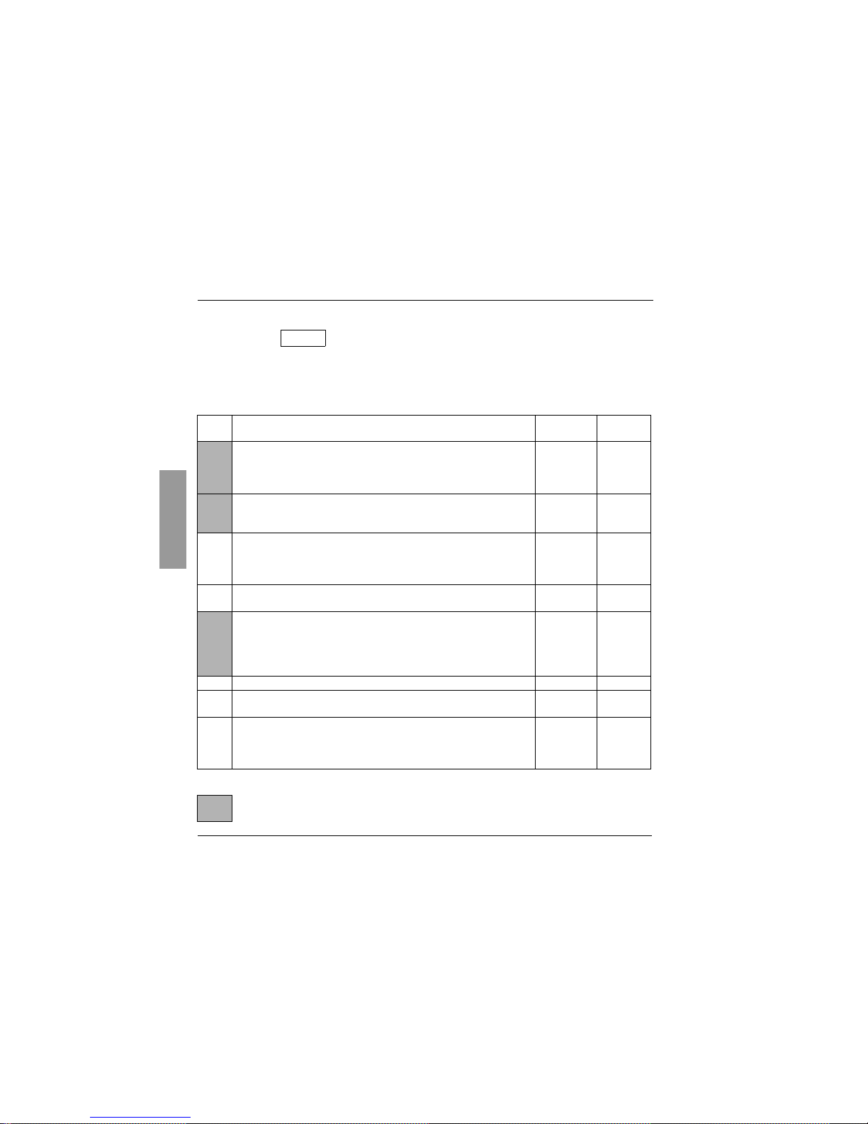
Settings
Adjust menu
These adjustment parameters can be modified with the speed controller stopped or
running. Ensure that changes made during operation do not present any danger.
Changes should preferably be made with the speed controller stopped.
(1) In is the nominal speed controller current shown in the catalogue and on the speed controller rating plate.
Code Assignment Adjustment
range
Factory
setting
-LFr
Speed reference via the display module.
This parameter appears with the remote display module option if control of
the speed controller via the display module is enabled : LCC parameter in IO- menu.
LSP to HSP
-rPI
PI reference
This parameter appears if analog input AIC/AI2 is assigned to the internal PI
function (AIC = PII).
0.0 to 100.0 %
0.0
-rOt
Direction of operation.
This parameter appears if the "local control" option is present .
It defines the direction of operation :
- forward : For, - reverse : rrS
For - rrS For
-ACC
-dEC
Acceleration and deceleration ramp times.
Defined to range from 0 to nominal motor frequency (FrS)
0,0 to 3600 s
0.0 to 3600 s
3 s
3 s
-AC2
-dE2
2nd acceleration ramp time
2nd deceleration ramp time
These parameters are accessible if the ramp switching threshold (Frt
parameter in the drC- menu) is other than 0 Hz or if a logic input is assigned
to ramp switching.
0,0 to 3600 s
0.0 to 3600 s
5 s
5 s
-LSP
Low speed 0 to HSP 0 Hz
-HSP
High speed : ensure that this setting is appropriate for the motor and the
application.
LSP to tFr bFr
-ItH
Current used for the motor thermal protection. Set ItH to the nominal current
marked on the motor rating plate.
To disable thermal protection, increase the value to the maximum (ntH
displayed).
0,50 to 1,15
In (1)
In (1)
The parameters in shaded boxes appear if the corresponding functions have been configured
in the drC- or I-O- menus.
SEt-
Page 39
85
ENGLISH
Settings
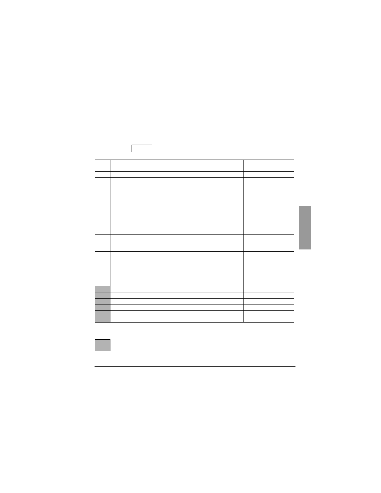
Adjust menu (continued)
(1) In is the nominal speed controller current shown in the catalogue and on the speed controller rating
plate.
Code Assignment Adjustment
range
Factory
setting
-UFr
Optimizes the torque at very low speed 0 to 100 % 20
-SLP
Adjusts the slip compensation around the value set by the nominal motor
speed. This parameter only appears if parameter UFt = n in the drC- menu.
0.0 to 5.0 Hz According
to controller
output
-FLG
Frequency loop gain
Linked to the inertia and the resistive torque of the driven mechanism :
- machines with high resistive torque or high inertia : gradually reduce the
gain in the range 33 to 0
- machines with fast cycles, low resistive torque and low inertia : gradually
increase the gain in the range 33 to 100. Too high a gain may result in
operating instability.
0 to 100 % 33
-IdC
Level of DC injection braking current
After 5 seconds the injection current is peak limited at 0.5 Ith if it is set at a
higher value.
0.1 ItH to
In (1)
0.7 In (1)
-tdC
DC injection standstill braking time
If the time is increased to 25.5 s, "Cont" is displayed. The DC injection is then
continuous at standstill.
0 to 25,4 s
Cont.
0.5 s
-JPF
Skip frequency prevents prolonged operation at a frequency range of 2 Hz
around JPF. This function prevents a critical speed which leads to resonance.
Setting the function to 0 renders it inactive.
0 to HSP 0 Hz
-JOG
Jog operating frequency 0 to 10 Hz 10 Hz
-rPG
PI regulator proportional gain 0,01 to 100 1
-rIG
PI regulator integral gain 0.01 to 100 / s 1 / s
-FbS
PI feedback multiplication coefficient 0.1 to 100 1
-PIC
Reversal of the direction of correction of the PI regulator :
no : normal, YES : reverse
no - YES no
The parameters in shaded boxes appear if the corresponding functions have been configured
in the drC- or I-O- menus.
SEt-
Page 40
86
ENGLISH
Settings
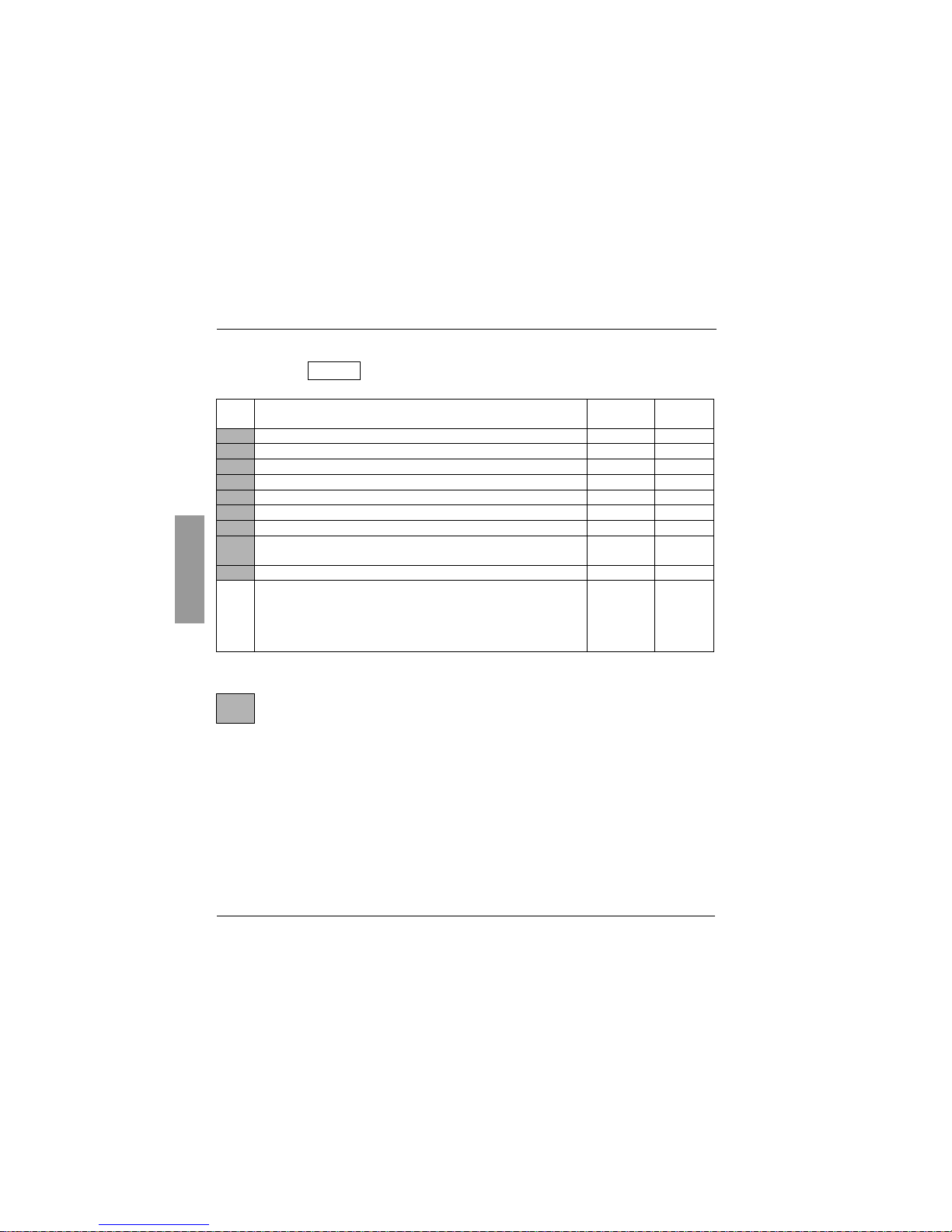
Adjust menu (continued)
(1) In is the nominal speed controller current shown in the catalogue and on the speed controller rating
plate.
Code Assignment Adjustment
range
Factory
setting
-SP2
2 nd preset speed LSP to HSP 10 Hz
-SP3
3 rd preset speed LSP to HSP 15 Hz
-SP4
4 th preset speed LSP to HSP 20 Hz
-SP5
5 th preset speed LSP to HSP 25 Hz
-SP6
6 th preset speed LSP to HSP 30 Hz
-SP7
7 th preset speed LSP to HSP 35 Hz
-Ftd
Motor frequency threshold beyond which the contact on relay R2 closes 0 to HSP bFr
-Ctd
Current threshold beyond which the contact on relay R2 closes 0,1 ItH to
1.5 In (1)
1.5 In (1)
-ttd
Motor thermal state threshold beyond which the contact on relay R2 closes 1 to 118 % 100 %
-tLS
Low speed operating time
Following operation at LSP for a defined period, a motor stop is requested
automatically. The motor restarts if the frequency reference is greater than
LSP and if a run command is still present.
Caution : value 0 corresponds to an unlimited period
0 to 25.5 s 0 (no time
limit)
The parameters in shaded boxes appear if the corresponding functions have been configured
in the drC- or I-O- menus.
SEt-
Page 41
87
ENGLISH
Settings
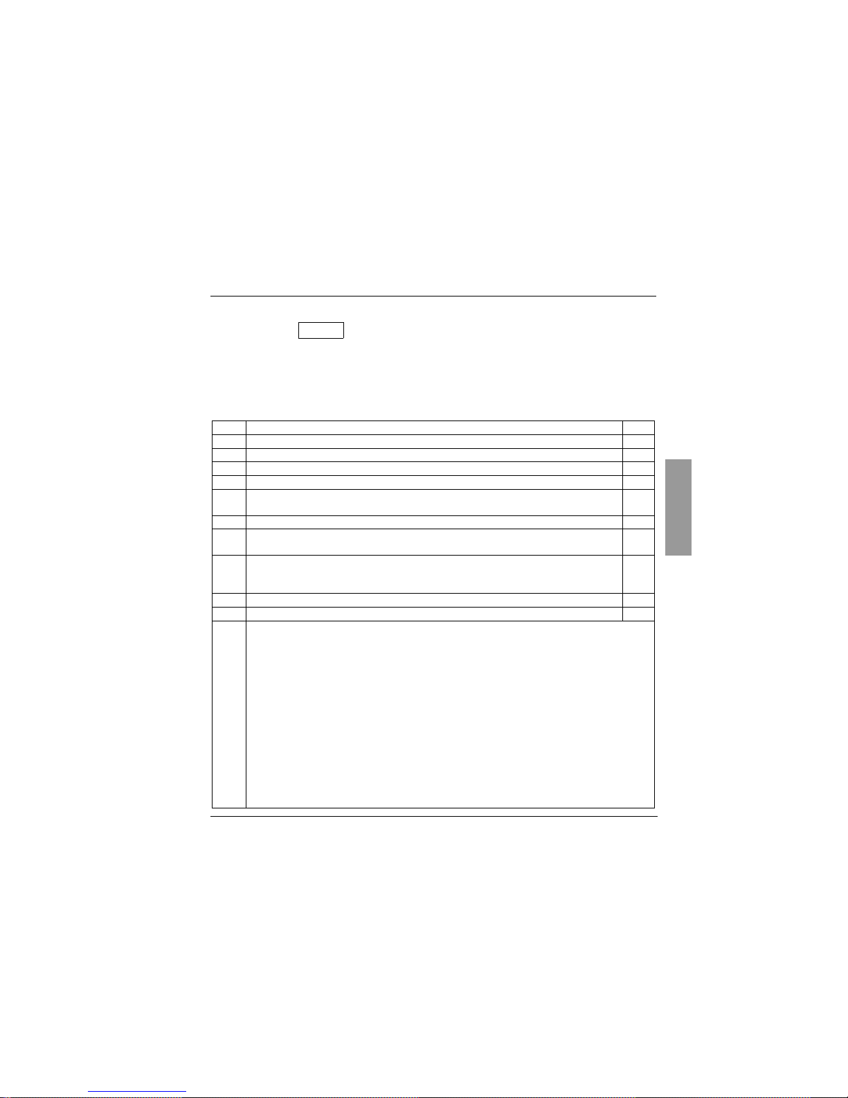
Display menu
(choice of parameter to be displayed during operation, view the last
fault, speed controller software version and access code)
The display chosen is saved by :
- Pressing the ENT key once: the choice is temporary, it will be cleared at the next power up.
- Pressing the ENT key twice : the choice is permanent. The second press on ENT exits the SUP- menu.
The following parameters can be accessed, with the speed controller stopped or running.
Code Parameter Unit
-FrH
Display the frequency reference Hz
-rFr
Display the output frequency applied to the motor Hz
-SPd
Display the value calculated by the speed controller (rFr x SdS) –
-LCr
Display the motor current A
-OPr
Display the power supplied by the motor, estimated by the speed controller.
100 % corresponds to the nominal speed controller power.
%
-ULn
Display the line voltage V
-tHr
Display the motor thermal state : 100% corresponds to the nominal thermal state.
Above 118%, the speed controller triggers an OLF fault (motor overload)
%
-tHd
Display the speed controller thermal state : 100% corresponds to the nominal thermal state.
Above 118%, the speed controller triggers an OHF fault (drive overheated)
It can be reset below 70%.
%
-LFt
View the last fault which appeared. If there has been no fault, the display shows : noF. –
-CPU
Speed controller software version –
-COd
Parameter which can only be seen and accessed using a remote display module option or PC software.
Access code : 0 to 9999. Value 0 (factory setting) does not prevent access. All other values lock access
to the SEt-, drC- and I-O- menus.
To lock access to the speed controller, the code can be incremented using (
s t
) then saved using (ENT).
• Do not forget to make a note of the code, as once it has been saved, it is no longer
displayed.
• If a code other than 0 is configured, access to the menus requires a remote
display module option or PC software.
To access the menus on a speed controller which is locked by a code, the code can be incremented using
(
s t
) and confirmed with (ENT) :
• If the correct access code is displayed, it flashes, and code 0 can then be configured in order to access
the menus.
• If an incorrect code is displayed, the speed controller returns to the initial display (rdY).
SUP-
Page 42
88
ENGLISH
Settings
Display menu
(continued)
.
Code Parameter
----
Display of speed controller status : the operating phase of the motor or a fault.
- Init : Initialization sequence
- rdY : Speed controller ready
- 43.0 : Display of the frequency reference
- dcb : DC injection braking in progress
- rtrY : Automatic restart in progress
- nSt : Freewheel stop command
- FSt : Fast stop command
SUP-
Page 43

89
ENGLISH
Maintenance
Servicing
The BLEMO-ER21 does not require any preventative maintenance. It is nevertheless advisable to carry
out the following operations regularly :
- Check the condition and tightness of connections.
- Check that the temperature around the unit remains at an acceptable level and that the
ventilation is effective (average service life of fans : 3 to 5 years depending on operating
conditions).
- Remove any dust from the speed controller.
Assistance with maintenance
If there is a problem when starting up or during operation, firstly check that the recommendations relating
to the environment, mounting and connections have been followed.
The first fault detected is memorized and displayed on the screen : the speed controller locks and fault
relay R1 is tripped.
Clearing faults
Switch off the speed controller power supply in the event of a fault which cannot be reset.
Wait for the LED and the display to go off completely.
Find the cause of the fault in order to correct it.
Restore the power supply : this will clear the fault if it has disappeared.
In some cases there may be an automatic restart after the fault has disappeared if this function has been
programmed.
Display menu :
This is used to prevent and find the causes of faults by displaying the speed controller status and its
current values.
Spares and repairs :
Consult BLEMO Frequenzumrichter product support.
Page 44
90
ENGLISH
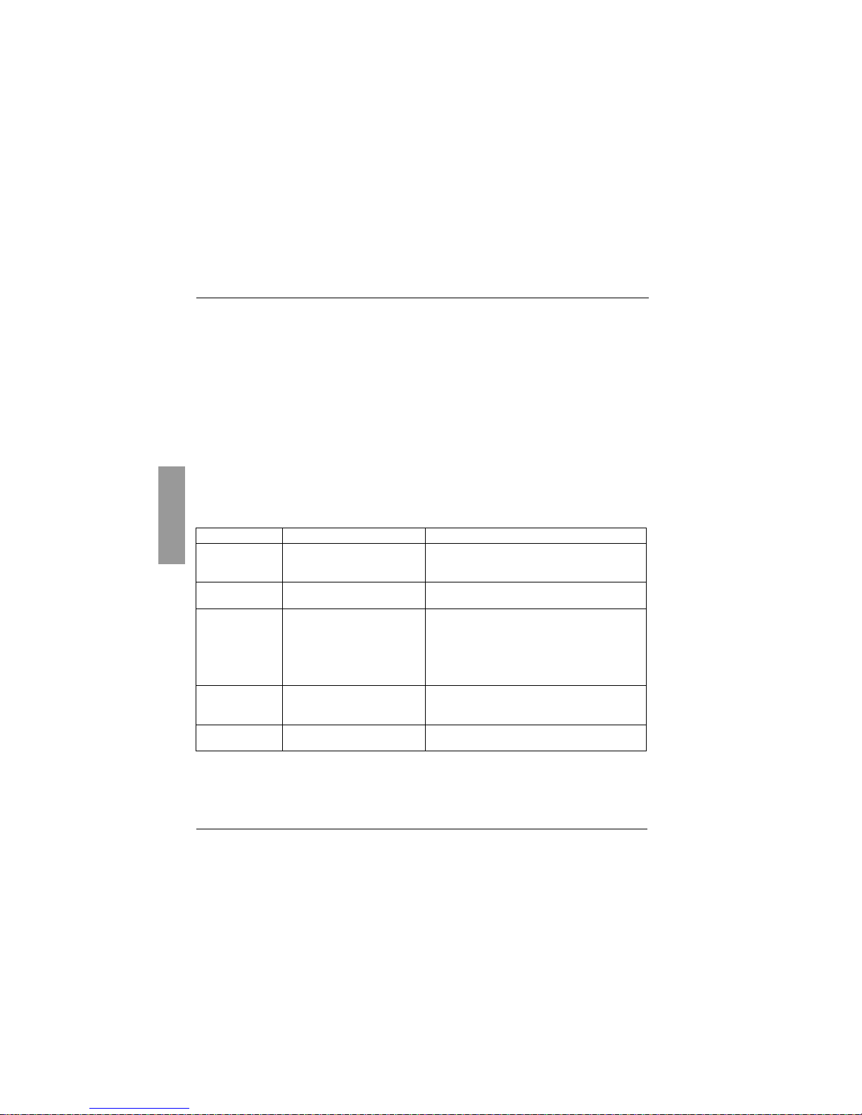
Faults - Causes - Remedies
Speed controller does not start, no fault displayed
• The assignment of the "Fast stop" or "Freewheel stop" functions will prevent the controller from starting
if the corresponding logic inputs are not powered up. The BLEMO-ER21 then displays "nSt" in freewheel
stop mode and "FSt" in fast stop mode. This is normal since these functions are active at zero so that
the controller will be stopped safely if there is a wire break.
• On power-up or a manual fault reset or after a stop command, the motor can only be powered once the
"forward", "reverse" and "DC injection stop" commands have been reset. If they have not been reset, the
speed controller will display "rdY" but will not start. If the automatic restart function is configured
(parameter Atr in the drC menu), these commands are taken into account without a reset being
necessary.
Faults which cannot be reset automatically
The cause of the fault must be corrected before resetting by powering down and then powering up.
Fault
Probable cause
Remedy
-OCF
overcurrent
- ramp too short
- inertia or load too high
- mechanical blocking
- Check the settings.
- Check the motor/speed controller/load sizing.
- Check the state of the mechanism.
-SCF
motor short-circuit
- short-circuit or earthing at the
speed controller output
- Check the cables connecting the speed controller to
the motor, and the insulation of the motor.
-InF
internal fault
- internal fault - Check the environment (electromagnetic
compatibility).
- Check that the "local control" option has not been
connected or disconnected with the controller powered
up.
- Send the speed controller to be checked/repaired.
-tnF
auto-tuning fault
- special motor or motor whose
power is not suitable for the speed
controller
- Use the L or the P ratio.
-EEF
internal fault
- internal fault - Send the speed controller to be checked/repaired.
Page 45
91
ENGLISH
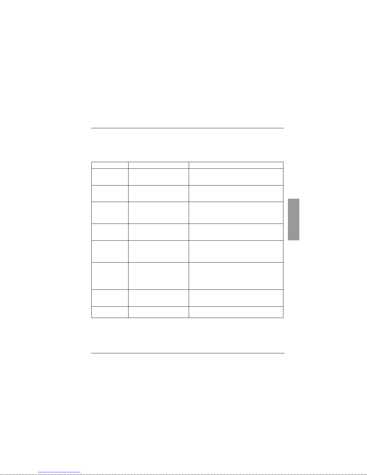
Faults - Causes - Remedies
Faults which can be reset with the automatic restart function, after the
cause has disappeared
Fault
Probable cause
Remedy
-OHF
speed controller
overload
- I
2
t too high or
- speed controller temperature too
high
- Check the motor load, the speed controller ventilation
and the environment. Wait for the controller to cool
before restarting.
-OLF
motor overload
- tripped by I
2
t motor being too high - Check the setting of the motor thermal protection,
check the motor load. Wait for the controller to cool
before restarting.
-OSF
overvoltage in
steady state or
during acceleration
- line voltage too high
- disturbed line supply
- Check the line voltage.
-USF
undervoltage
- line supply too low
- transient voltage dip
- damaged load resistor
- Check the voltage and the voltage parameter.
- Reset.
- Send the speed controller to be checked/repaired.
-ObF
overvoltage
during deceleration
- braking too sudden
or driving load
- Increase the deceleration time.
- Install a braking resistor if necessary.
- Activate the brA function if it is compatible with the
application.
-PHF
motor phase
phase failure
- speed controller incorrectly
supplied or a fuse blown
- transient phase fault
- 3-phase ER21 used on a single
phase line supply
- Check the power connection and the fuses.
- Reset
- Use a 3-phase line supply.
-OPF
motor phase
failure
- loss of a phase at the speed
controller output
- Check the connections from the speed controller to the
motor.
-SLF
serial link failure
- incorrect connection on the
speed controller connector
- Check the serial link connection on the speed
controller connector.
Page 46
92
ENGLISH
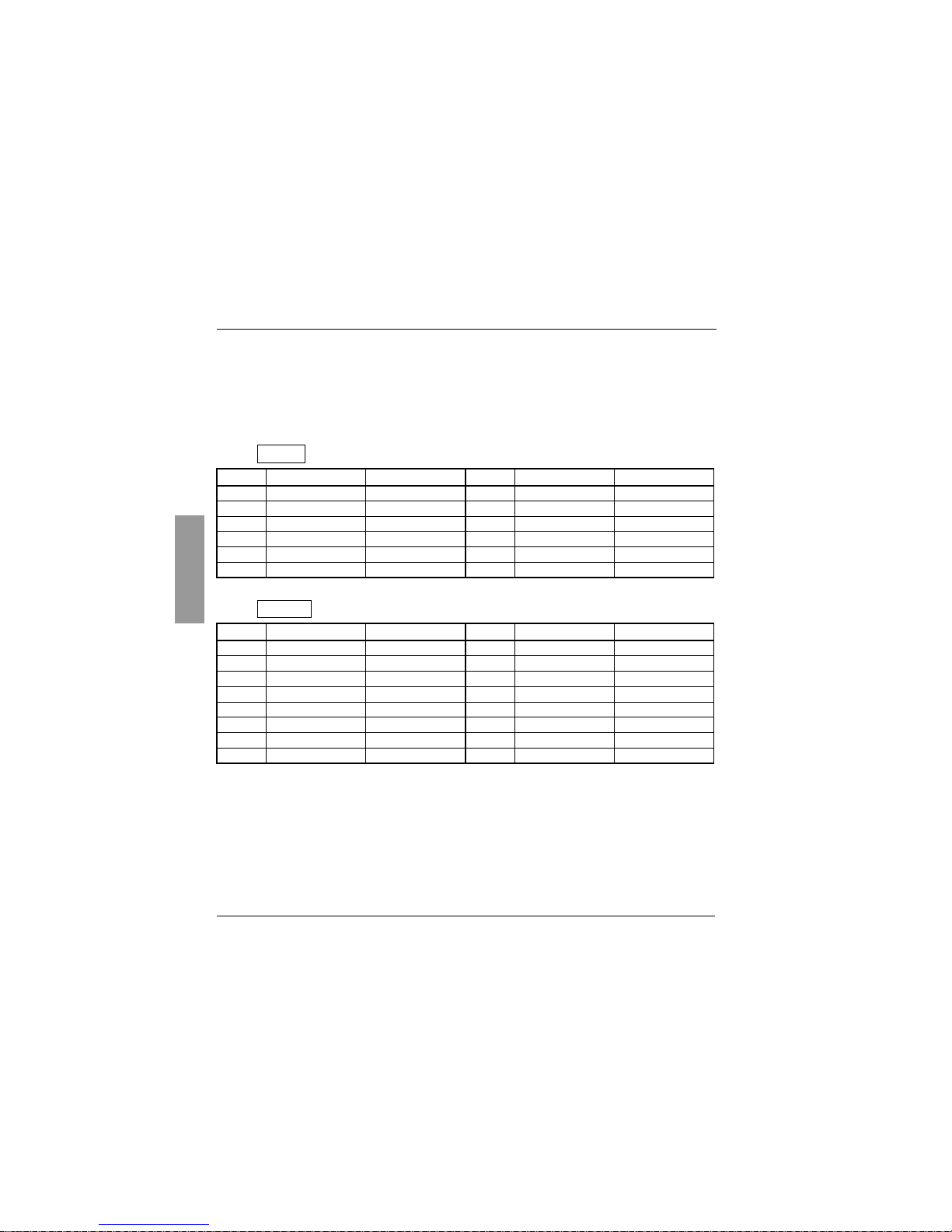
Configuration/Settings Tables
Speed controller BLEMO-ER21.......................................................................................................................
Optional customer identification no. : ..............................................................................................................
Software version (CPU parameter in the SUP menu) : ..................................................................................
Optional access code : ..........................................................................................................................
Local control option no
yes
Menu (inputs/outputs)
Menu (drive)
Code
Factory setting Customer setting
Code
Factory setting Customer setting
-tCC
2C
-LI2
rrS
-LI3
PS2
-LI4
PS4
-AIC
SAI
-CrL
4 mA mA
-CrH
20 mA mA
-AO
rFr
-AOt
0 mA mA
-r2
SrA
-Add
1
-bdr
19.2
Code
Factory setting
Customer setting Code
Factory setting
Customer setting
-UnS
V V
-FrS
Hz Hz
-tUn
no
-tFr
Hz Hz
-UFt
n
-brA
YES
-Frt
0 Hz Hz
-SFr
4.0 kHz kHz
-nrd
YES
-Atr
no
-OPL
YES
-IPL
YES
-StP
no
-FLr
no
-drn
no
-SdS
30
drC-
Page 47
93
ENGLISH
Configuration/Settings Tables
Menu (settings)
Code
Factory setting
Customer setting Code
Factory setting
Customer setting
-rPI
0.0 % Control
-rOt
For Control
-ACC
3.0 s s
-dEC
3.0 s s
-AC2
5.0 s s
-dE2
5.0 s s
-LSP
0.0 Hz Hz
-HSP
Hz Hz
-ItH
A A
-UFr
20 % %
-SLP
Hz Hz
-FLG
33 % %
-IdC
A A
-tdC
0.5 s s
-JPF
0 Hz Hz
-JOG
10 Hz Hz
-rPG
1
-rIG
1 /s /s
-FbS
1
-PIC
no
-SP2
10 Hz Hz
-SP3
15 Hz Hz
-SP4
20 Hz Hz
-SP5
25 Hz Hz
-SP6
30 Hz Hz
-SP7
35 Hz Hz
-Ftd
Hz Hz
-Ctd
A A
-ttd
100 % %
-tLS
0.0 s s
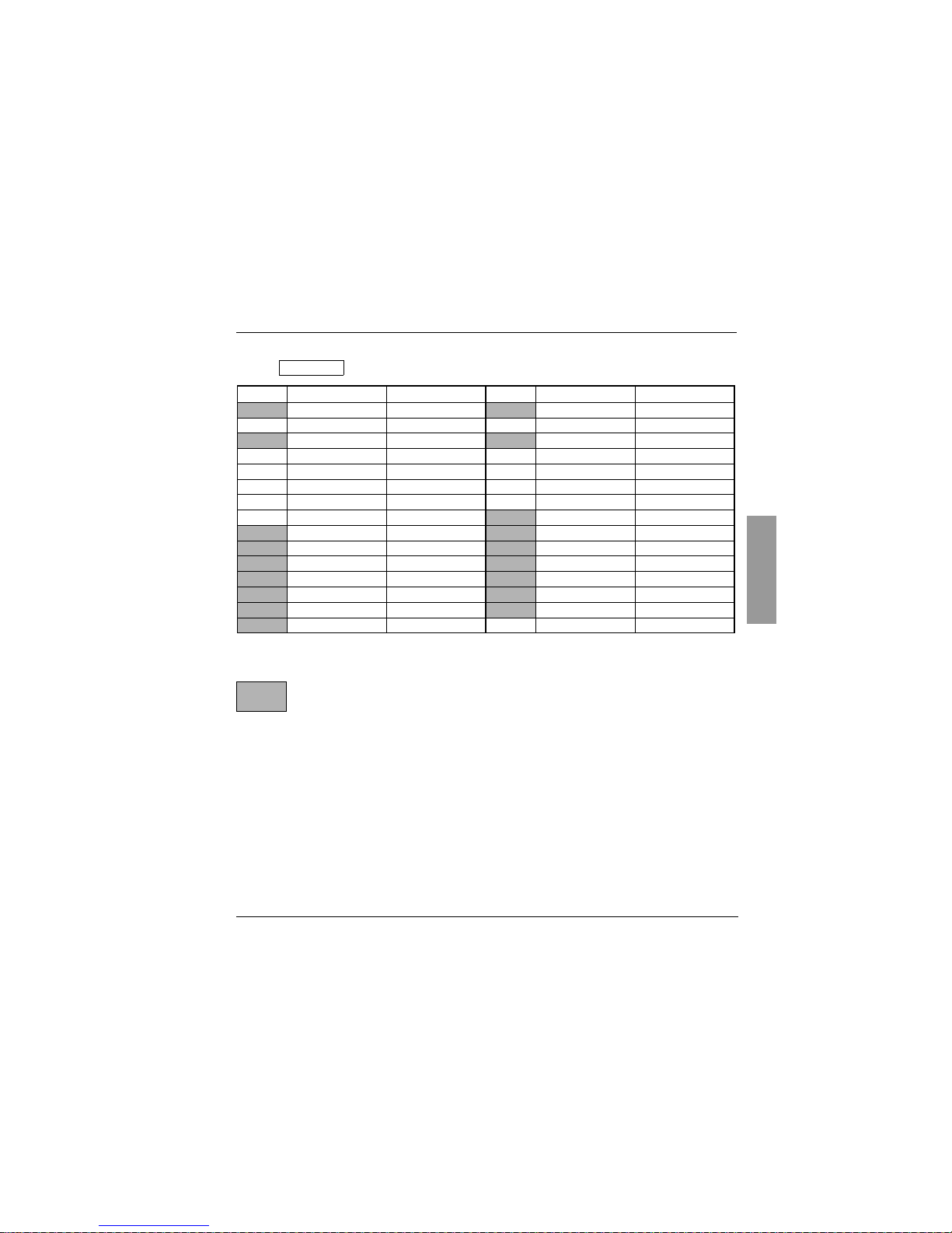
The parameters in shaded boxes appear if the corresponding functions have been configured in
the drC- or I-O- menus.
SEt-
Page 48

BLEMO
Frequenzumrichter
Siemensstraße 4
D-63110 Rodgau – Dudenhofen
 Loading...