

Page 1

700/900 Series Ventilators
Operator User Manual
Page 2
700/900 Series
Part Number: 140UM000
Ventilators
MODIFICATIONS LABEL
ECN 1
ECN 6
ECN 2
ECN 7 ECN 8 ECN 9 ECN 10
User
Manual
ECN 3
ECN 4
ECN 5
700/900 Series Ventilators User Manual 1
0120
Issue 1/ March 2006
Page 3

IMPORTANT
Read this manual before operating the machine.
Read the Vaporizer manual before operating the
machine.
Read the Absorber manual before operating the
machine.
The user must be familiar with the machine and
its various functions before using it on a patient.
2
700/900 Series Ventilators User Manual
Page 4

Contents
Contents
How to use this manual ......................................................................................8
SECTION 1 - INTRODUCTION ...............................................9
1.1 Symbols & Abbreviations ......................................................................... 10
1.2 Identify your Ventilator ............................................................................. 12
1.3 Description of the Ventilator ................................................................... 13
1.3.1 Overview ........................................................................................... 13
1.3.2 Features ............................................................................................. 14
1.3.2.1 Controls & Indicators ........................................................ 14
1.3.2.2 Microprocessor Control ................................................... 14
1.3.2.3 Dual Ventilation Mode .................................................... 14
1.3.2.4 Pressure Limit Control ...................................................... 14
1.3.2.5 Built-In Ventilator Pre-Use Test ...................................... 14
1.3.2.6 Comprehensive Pressure Monitoring and Alarms ..... 14
1.3.2.7 Spirometry ........................................................................... 15
1.3.2.8 Battery Backup ................................................................... 15
1.3.2.9 Calibration Connector ...................................................... 15
1.3.2.10 Data Output ....................................................................... 15
1.3.3 Operating Modes ............................................................................. 16
1.3.3.1 Volume Control ................................................................ 17
1.3.3.2 Pressure Control ............................................................... 17
1.3.3.3 Pressure Support .............................................................. 18
1.3.3.4 SIMV + PSV ........................................................................ 18
1.3.3.5 Inspiratory Pause .............................................................. 18
1.3.3.6 Sigh ...................................................................................... 19
1.3.3.7 Pressure Support .............................................................. 19
1.3.4 Principles of Operation ................................................................. 20
1.3.5 Parameters ...................................................................................... 22
1.3.5.1 PEEP .................................................................................... 22
1.3.5.2 Trigger ................................................................................. 23
1.3.5.3 Support Pressure .............................................................. 23
1.3.5.4 Fresh Gas Compensation ............................................... 23
1.3.5.5 Oxygen ................................................................................ 23
1.3.5.6 Tidal Volume ...................................................................... 23
1.3.5.7 Minute Volume ................................................................. 23
1.3.5.8 Expired Tidal Volume ....................................................... 23
700/900 Series Ventilators User Manual 3
Page 5

Contents
1.3.5.9 BPM (Frequency Control) ............................................... 23
1.3.5.10 I:E Ratio ..............................................................................24
1.3.5.11 Pressure Limit ................................................................... 24
1.3.5.12 Peak Pressure ................................................................... 24
1.3.5.13 Mean Pressure ................................................................. 24
1.3.5.14 Compliance .......................................................................24
1.4 User Interface .............................................................................................. 25
1.4.1 Front Panel ....................................................................................... 25
1.4.1.1 Normal Screen .................................................................. 26
1.4.1.2 Activity Display Area ........................................................ 26
1.4.1.3 Alarms Display Area ......................................................... 27
1.4.1.4 Parameter Display Area .................................................. 27
1.4.1.5 TrakWheel & Touchscreen .............................................. 28
1.4.1.5.1 Trak Wheel .................................................... 28
1.4.1.5.2 Touchscreen ................................................ 29
1.4.2 Battery Status LEDs ....................................................................... 30
1.4.3 Menu Tree ...................................................................................... 31
1.4.3.1 Setup Menu ..................................................................... 31
1.4.3.2 Defaults Menu ................................................................ 32
1.4.3.3 Alarm Setup .................................................................... 32
SECTION 2 - USING THE VENTILATOR ................................... 33
2.1 Operation ................................................................................................... 33
2.1.1 Powering up the Ventilator ......................................................33
2.1.2 Starting the Ventilator ..................................................................33
2.1.3 Stopping the Ventilator ...............................................................33
2.1.4 Activating and monitoring Alarms ............................................ 33
2.1.5 End of Case .................................................................................... 33
2.1.6 Powering down the Ventilator ..................................................33
2.2 Pre-use Testing .......................................................................................... 34
2.2.1 Pre-use Test Error Messages ....................................................... 37
2.2.2 Compliance Test Skipped ............................................................. 39
2.2.3 Fresh Gas ......................................................................................... 39
2.2.4 BAG/Standby/Run ......................................................................... 41
2.2.5 I:E Setting ......................................................................................... 42
2.2.6 Oxygen Calibration ........................................................................ 43
2.3 The Measurements Menu ........................................................................ 44
2.3.1 Adult and Pediatric ........................................................................ 45
2.4 Sensor Placement ....................................................................................... 46
2.5 The Waveform Select Menu .................................................................... 48
2.6 Spirometry ................................................................................................... 48
4
700/900 Series Ventilators User Manual
Page 6

Contents
Recalling loops ........................................................................................... 49
2.6.1 Pressure/Volume ............................................................................ 50
2.6.2 Flow/Volume .................................................................................. 50
2.6.3 Pneumothorax during Laparoscopy .......................................... 51
2.7 Airway Pressure .......................................................................................... 52
2.7.1 Airway Flow ..................................................................................... 52
2.8 Mode Selection Menu ............................................................................... 53
2.8.1 Cardiac Bypass ................................................................................. 53
2.8.2 Setting Parameters .......................................................................... 54
2.9 Alarms ........................................................................................................... 55
2.9.1 Alarms Summary ............................................................................. 56
2.9.2 Pre-set Alarms .................................................................................. 57
2.9.3 Apnea Alarms ................................................................................... 57
2.9.4 Low Supply Gas Pressure Alarm ................................................. 57
2.9.5 Vent Inoperative Alarm .................................................................. 57
2.9.6 Setting Error Alarm ......................................................................... 58
2.9.7 Sustained Pressure Alarm .............................................................. 58
2.9.8 Power Fail and Battery Low Alarms ........................................... 59
2.9.9 No Charge ......................................................................................... 59
2.9.10 Comms Fail ...................................................................................... 59
2.9.11 PEEP Alarm ...................................................................................... 59
2.9.12 Under Pressure Alarm (PCV mode only) ................................. 59
2.10 User Defined Alarms ............................................................................... 60
2.10.1 Pressure High Alarm ..................................................................... 60
2.10.2 Pressure Low Alarm ..................................................................... 60
2.10.3 MV High Alarm .............................................................................. 60
2.10.4 MV Low Alarm ............................................................................... 60
2.10.5 High BPM Alarm ........................................................................... 61
2.10.6 Low BPM Alarm ............................................................................ 61
2.10.7 High Oxygen Alarm ...................................................................... 61
2.10.8 Low Oxygen Alarm ....................................................................... 61
2.10.9 Fresh Gas too High ....................................................................... 61
2.11 Auto Alarms .............................................................................................. 62
2.12 The Alarms Menu ..................................................................................... 63
2.12.1 Setting Alarms .............................................................................. 63
2.12.2 Alarm Mute .................................................................................. 64
2.12.2.1 Setting the Alarm Mute Time ................................. 64
2.12.3 Setting the Apnea Time .............................................................. 65
2.13 The Defaults Menu .................................................................................. 66
700/900 Series Ventilators User Manual 5
Page 7

Contents
2.13.1 Change Names ............................................................................. 66
2.13.2 Save Hospital Defaults ................................................................ 68
2.13.3 Saving and Recalling Settings .................................................... 68
2.13.4 Save Current Settings .................................................................. 68
2.13.5 Recall Previous Settings .............................................................. 69
2.13.6 Configuration ................................................................................ 70
2.13.7 Setup ............................................................................................... 70
2.13.8 Fresh Gas Calibration .................................................................. 71
2.13.9 Sigh Setting ................................................................................... 71
2.13.10 Absorber Setting ......................................................................... 71
2.13.11 System Information .................................................................... 71
SECTION 3 - INSTALLATION .................................................... 73
3.1 Cautions ........................................................................................................ 73
3.2 Pre-use Checks ............................................................................................ 77
3.3 Discharged Battery ..................................................................................... 79
3.4 Exchanging Bellows Units ......................................................................... 80
3.4.1 Installing Adult Bellows ................................................................. 81
3.5 Pre-use Test ................................................................................................. 82
3.5.1 Fresh Gas ........................................................................................82
3.5.2 Compliance ......................................................................................82
SECTION 4 - ROUTINE USER MAINTENANCE ........................ 84
4.1 Weekly Checks ............................................................................................. 84
4.1.1 Control Unit ..................................................................................... 84
4.2 Six-Monthly Checks .................................................................................... 84
4.2.1 Bellows .............................................................................................84
4.3 Other Maintenance .................................................................................... 85
4.4 Exchanging Fuses ........................................................................................ 85
4.5 Cleaning and Sterilization ......................................................................... 86
4.5.1 Ventilator Surfaces ......................................................................... 86
4.5.2 Pop-off Valve Seat ......................................................................... 86
4.5.3 Patient Airway Flow Sensor ......................................................... 88
4.5.4 Bellows .............................................................................................88
4.5.5 Methods of Sterilization ............................................................... 89
SECTION 5 - TROUBLESHOOTING .......................................... 91
SECTION 6 - APPENDICES ....................................................... 93
6.1 Performance Data ..................................................................................... 93
6.1.1 Notes on Performance Data ...................................................... 94
6.2 Dimensions ................................................................................................. 94
6.3 Factory Default Settings ........................................................................... 95
6
700/900 Series Ventilators User Manual
Page 8

Contents
6.4 Fixed Features ............................................................................................ 96
6.5 Mode Dependant Features ..................................................................... 97
6.6 Associated Equipment & Accessories ................................................... 98
6.7 External Communication Specification ..............................................100
6.7.1 Data Transmission Settings ......................................................100
6.7.2 Protocol ........................................................................................100
6.7.3 Set Messages ................................................................................101
6.7.4 Breathing Modes .........................................................................101
6.7.5 Breathing Control .......................................................................101
6.7.6 Measured Value Messages ........................................................102
6.7.7 Event Message .............................................................................102
6.7.8 Alarm Message ............................................................................103
6.7.9 Error Codes ..................................................................................104
SECTION 7 - NOTICES .............................................................105
7.1 Product Improvement ...........................................................................105
7.2 Responsibilities of the User ...................................................................105
7.3 Responsibilities of the Manufacturer ..................................................105
7.4 Disclaimer .................................................................................................106
7.5 Technology Disclaimer ...........................................................................106
7.6 Note to Service Personnel ....................................................................106
7.7 Copyright ..................................................................................................107
7.8 CE Marking ...............................................................................................107
7.9 Trademarks & Acknowledgements ......................................................108
7.10 Hazard Notices .......................................................................................109
7.10.1 Hazard Information ................................................................110
7.10.2 Cautionary Notices .................................................................113
SECTION 8 - GLOSSARY .........................................................116
SECTION 9 - INDEX .................................................................117
List of Figures
Figure 1 700/900 Series Ventilator ................................................................13
Figure 2 Pneumatic System Diagram ............................................................21
Figure 3 Front Panel ............................................................................................25
Figure 4 Airway Sensor Placement .................................................................47
Figure 5 Exchanging Bellows Units ................................................................80
Figure 6 Exchanging Fuses ................................................................................85
Figure 7 Exchanging Fuses ................................................................................85
Figure 8 Exchanging Fuses ................................................................................85
Figure 9 Removing the pop-off valve ............................................................87
700/900 Series Ventilators User Manual 7
Page 9

Blease 700/900 Series Ventilators
How to Use This Manual
This manual is designed as a guide for learning to operate the 700/900 Series
Ventilators, and also as a reference tool to use once you are familiar with the
system.
For information on disclaimers, contact information, trademarks, cautions
warnings and hazards, refer to section 7 at the back of this manual.
8
700/900 Series Ventilators User Manual
Page 10

Section 1 - 700/900 Series Ventilators
1. Introduction
1. Introduction
Welcome to the User and Routine Maintenance Manual for the Blease 700/900
Series Ventilators.
This handbook is intended for users of the ventilator and contains detailed
installation and operating instructions. It also includes cleaning and sterilization
methods, basic troubleshooting and routine maintenance procedures.
Personnel operating the ventilator must become thoroughly familiar with the
instructions contained in this handbook prior to using the ventilator with patients.
The Blease 700/900 Series ventilators are intended for use by a qualified
practitioner under the direction of a qualified anesthetist. When the ventilator is
connected to a patient, it is recommended that a licensed medical practitioner be
in attendance at all times to react to an alarm or other indication of a problem.
WARNING: Incorrect use of the equipment described herein may
result in injury to the patient. Read this manual before operating
the machine. You must be familiar with the machine and its
functions before using it on a patient.
To ensure correct functioning of the equipment it must be serviced at regular
intervals. The ventilator must be serviced or repaired only by qualified service
personnel using genuine Blease spare parts. Blease Medical will not otherwise
assume responsibility for the materials used, the work performed or any possible
consequences of the same.
In communication with Blease Medical, quote the model and serial number of the
equipment, with the approximate date of purchase.
If the unit is being returned for repair, indicate the nature of the fault or the work
you require to be carried out. Please obtain clearance from Blease Technical
Support before dispatch.
700/900 Series Ventilators User Manual 9
Page 11
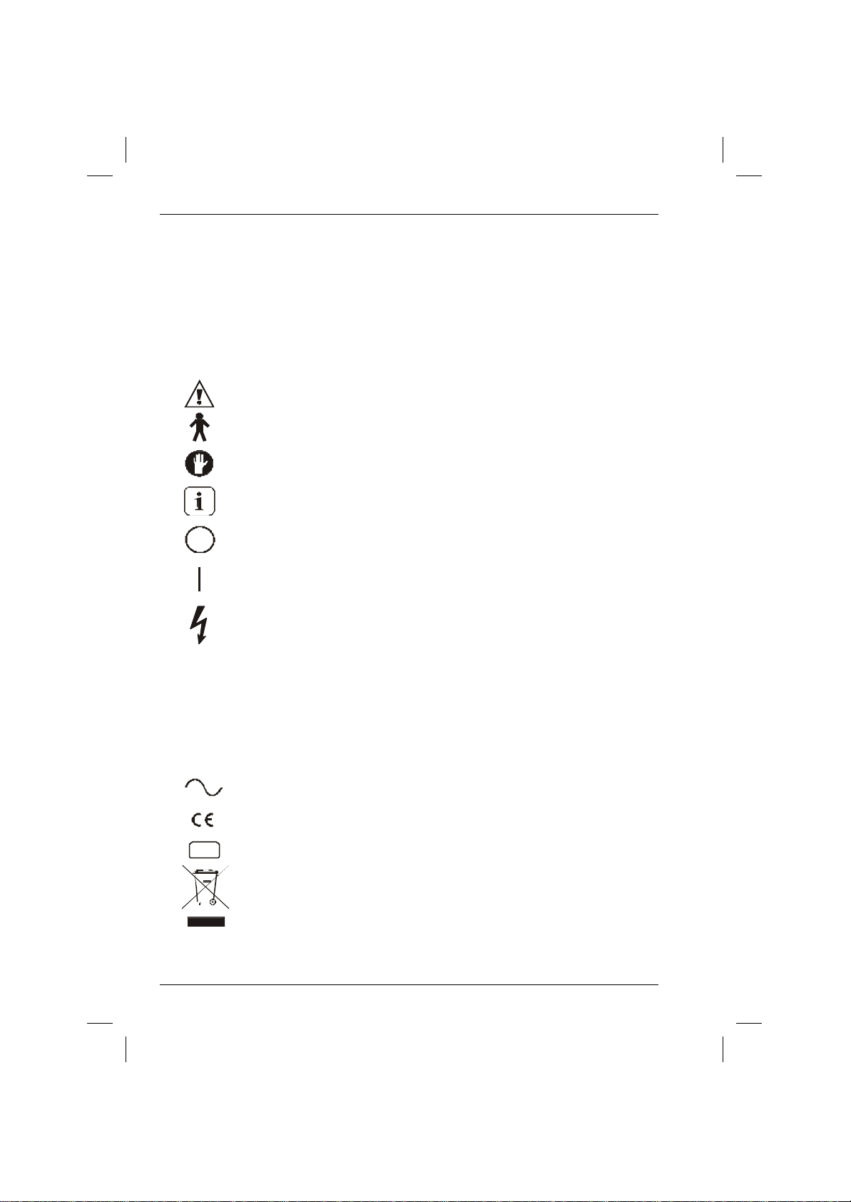
bpm BPM
Breaths per minute
Gauge pressure expressed in centimetres of water
Pounds per square inch
E of C
This symbol indicates that the waste of electrical and electronic
Symbols & Abbreviations
Section 1 - 700/900 Series Ventilators
1.1 Symbols and Abbreviations
cmH O
2
CPAP
PEEP
Continuous positive airway pressure
Positive end expiratory pressure
A ratio of inspiratory to expiratory timeI:E Ratio
IEC symbol to consult the instructions for use
IEC symbol denoting type of equipment (B)
WARNING: There is danger of personal injury to the
user or patient
Further relevant or helpful information
Power off
Power on
10
l/m lpm
ml
O
2
psi
psig
l
Dangerous voltage
Litres per minute
Millilitres
Oxygen
Pounds per square inch gauge
Litres
IEC symbol for alternating current
Confers approval under theEuropean Medical Device Directive
End of Case
equipment must not be disposed as unsorted municipal waste
and must be collected separately. Please contact an authorized
representative of the manufacturer for information concerning
the decommissioning of your equipment.
700/900 Series Ventilators User Manual
Page 12

Notes
700/900 Series Ventilators User Manual 11
Page 13

1. Description
Section 1 - 700/900 Series Ventilators
1.2 Identify your Ventilator
Use the table below to identify your ventilator model in
order to then refer to relevant sections of the manual.
700 Series
710 730 750 950 970 990
Screen size 8.4” 8.4” 8.4” 8.4” 8.4” 8.4”
Display Mono Mono Mono Color Color Color
Interface Touch &
Tidal volume
compensation
Fresh gas compensation Optional for
Configurable preset or
measured compliance
Vent mode
Volume Control
Pressure Control
SIMV + PSV
Pressure Support
Vent monitoring
Oxygen
Exhaled volume
monitoring
Airway Pressure
Trak
OEM/stand
alone
Touch &
Optional for
OEM/stand
alone
Touch & Trak Touch &
Trak
Optional for
OEM/stand
alone
900 series
Trak
Optional for
OEM/stand
alone
Touch &
Trak
Optional for
OEM/stand
alone
Touch &
Trak
Optional for
OEM/stand
alone
Pressure waveform
Flow waveform
Spirometry Loops
Data Output
12
700/900 Series Ventilators User Manual
Page 14
Section 1 - 700/900 Series Ventilators
1. Description
1.3 Description of the Ventilator
1.3.1 Overview
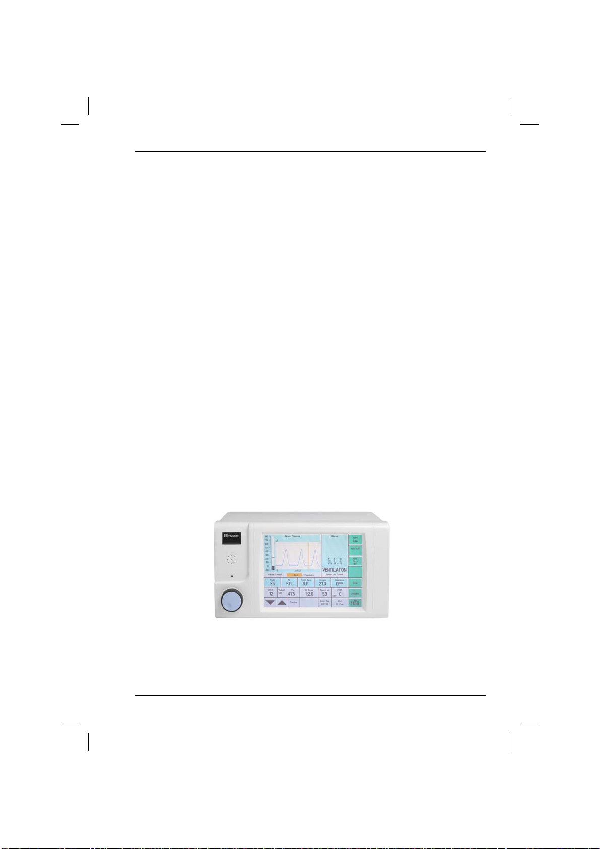
The 700/900 series ventilator is an advanced, microprocessor-controlled,
pneumatically driven ventilator which has been designed specifically for the
mechanical ventilation of adult and pediatric patients under general anesthesia.
The control unit houses the electronic and pneumatic control systems. It sets the
desired ventilatory parameters and generates alarm, warning and status messages.
The control unit also calculates and implements the functions necessary to drive
the bellows pneumatically.
The bellows assembly comprises a base and a bellows housing.
The 700/900 series ventilator is designed for use with a circle-type absorber and is
ideally suited to both low-flow and high-flow applications. The ventilator may also
be used with either a Bain-type coaxial circuit or a Jackson-Rees/Ayres T-piece
type pediatric circuit by using an adaptor.
There are variations based on the drive gas used (air or oxygen) and the drive gas
connector type (depending on the eventual country of use).
See 6.6 Associated Equipment and Accessories in the Appendices for ordering
information for the various types.
Throughout this manual, all figures and descriptions refer to a UK-
specification 700/900 series ventilator with oxygen drive gas supply.
Figure 1 700/900 Series Ventilator
700/900 Series Ventilators User Manual 13
Page 15

1. Description
Section 1 - 700/900 Series Ventilators
1.3.2 Features
1.3.2.1 Controls and Indicators
The operating parameters of the ventilator are set by a combination of touch
screen and Trak Wheel. Parameter values are shown on the touch screen.
1.3.2.2 Microprocessor Control
The built-in microprocessor control system makes it easy to upgrade and
customize the unit.
1.3.2.3 Dual Mode Ventilation
The ventilator can be used as either a flow generator or a pressure generator and
in both cases it is time cycled. Ventilation can therefore be tailored to meet all
patient requirements as each mode has an adult and pediatric application. In
addition to this the ventilator can be patient flow triggered.
1.3.2.4 Pressure Limit Control
This prevents barotrauma and gives maximum safety by ensuring accurate, safe
ventilation to a pre-set pressure limit.
1.3.2.5 Built-in Ventilator Pre-use Test
A ventilator Pre-use Test system ensures accurate ventilator delivery irrespective
of system back-pressure.
1.3.2.6 Comprehensive Pressure Monitoring and
Alarms
Selectable functions allow Airway, Peak and Mean pressure monitoring
spirometry, together with high, low and built-in airway flow detected Apnea
alarms.
Alarms are activated to guard reliably against disconnection, circuit leakage and
unachieved set volumes. The alarms are audible and visible. When activated, the
alarms are listed on the display.
The mains and battery alarms also have light emitting diode (LED) indication.
14
700/900 Series Ventilators User Manual
Page 16
Section 1 - 700/900 Series Ventilators
1. Description
1.3.2.7 Spirometry
The 700/900 series ventilator offers a simple, accurate and user- selectable display
of set and monitored tidal volumes.
The user also has a choice of one of the following on-screen waveforms:
1) Airway Pressure
2) Pressure/Volume
3) Flow/Volume
4) Airway Flow
1.3.2.8 Battery Back Up
The internal battery is automatically charged when the ventilator is connected to
the mains electrical supply. If the ventilator is in the 'ON' position and the mains
electrical power fails, the battery will provide continued operation of the ventilator
for a minimum of one hour if fully charged. A discharged battery takes approx. 8
hours to fully charge.
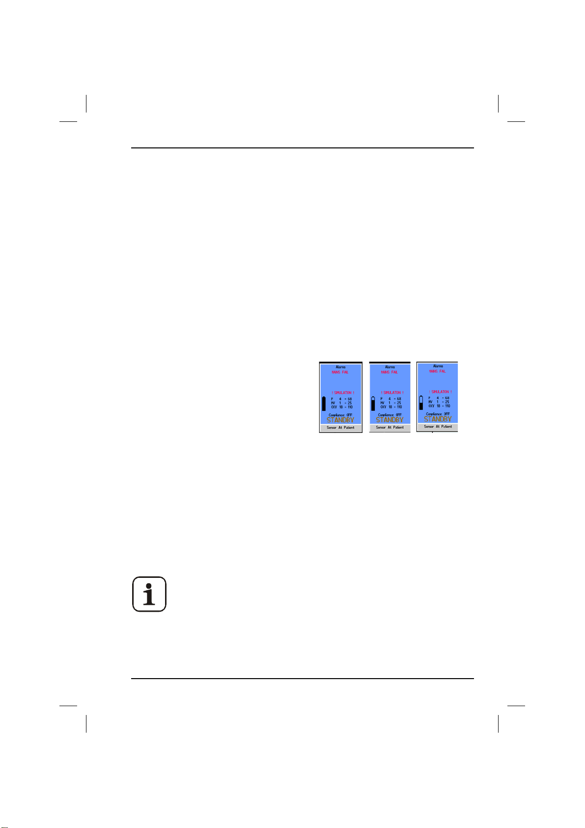
Low Battery Indicator
The mains fail alarm will be activated and a
battery symbol will appear in the alarms
panel. Symbol indicates how much charge is
left in the battery.
1.3.2.9 Calibration Connector
A 9-way D-type connector labeled CALIBRATION PORT is situated at the rear of
the ventilator. This is not an RS232 port and is used purely for calibration of the
700/900 series ventilator in conjunction with a special lead. Further details can be
obtained from Blease Technical Support.
1.3.2.10 Data Output
A 9-way D-Type connector is provided for RS232 connection of data to external
monitor systems.
Improper connection of equipment or any power sources to the
calibration port may permanently damage the ventilator. Only a
qualified technician should connect monitoring equipment to the
recorder output. Such equipment must be Blease-compatible and
meet the regulatory standards of the countries in which the
ventilator is used.
700/900 Series Ventilators User Manual 15
Page 17

1. Description
Section 1 - 700/900 Series Ventilators
1.3.3 Operating Modes
Some features of the ventilator are only available in certain
ventilatory modes
There are four ventilation modes; Volume Control, Pressure Control, Pressure
Support and SIMV + PSV.
The differences between the Adult and Pediatric modes are:
• The ventilator sustained pressure requires a greater pressure 'movement' in
adult mode to avoid being activated.
• Setting alarms and limits are, in general, optimized for lower pressures and
volumes to be used in pediatric mode.
WARNING: Short inspiratory times may result in inconsistent
breath delivery. Avoid control combinations which may produce
very short inspiratory times (<150 ms).
WARNING: Pressure limiting is a safety feature and is also used
in adult and pediatric mode to provide ventilation (PCV). It
should not be used for any other purpose, such as creation of
micro-breaths or emulation of specialized high frequency/low
volume ventilation systems, otherwise injury to the patient may
result.
16
700/900 Series Ventilators User Manual
Page 18
Section 1 - 700/900 Series Ventilators
1. Description
1.3.3.1 Volume Control
Volume Control Ventilation is a time cycled mode that delivers a set volume into
the circuit within a set time. The 700/900 series ventilator ensures that the
delivered volume is independent of any compression losses in the absorber,
bellows and associated tubing. Changes to fresh gas do not cause a permanent
change to the delivered volume, the ventilator automatically re-adjusts the
delivered tidal volume within the next few breaths.
When the tidal volume limit is reached, the ventilator immediately cycles into
expiration.
1.3.3.2 Pressure Control
Pressure Control Ventilation is a time-cycled mode where the ventilator maintains
the set inspiration pressure for the inspiratory period. The user sets the required
pressure.
The ventilator delivers volume until the set pressure limit is reached; then
maintains the pressure until the end of the inspiratory time.
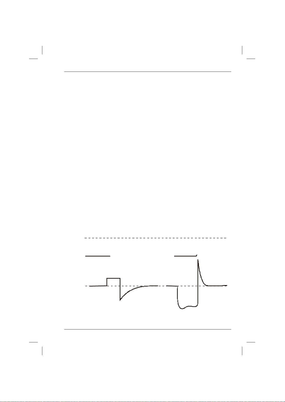
The effect of Volume and Pressure modes on the pressure and flow waveforms is
shown below:
Volume Control Mode Pressure Control Mode
Set pressure limit
Insp
Flow
Exp
700/900 Series Ventilators User Manual 17
Page 19

1. Description
Section 1 - 700/900 Series Ventilators
1.3.3.3 Pressure Support
When a patient takes a spontaneous breath from an anesthetic system the work
of breathing is harder than normal. To overcome this, the 700/900 series
ventilator detects the negative flow caused by the patient's attempt to breathe
and then initiates flow to assist the patient with the spontaneous breath. The flow
continues until the breathing circuit pressure reaches a pre-set value.
The user must set two parameters: the Trigger threshold (5 to 15 L/min), and the
Support Pressure which is referenced to the PEEP level (5 to 30 cm H2O).
1.3.3.4 SIMV + PSV
Synchronized Intermittent Mandatory Ventilation (SIMV) is an extension of the
spontaneous mode in so far as the patient can take breaths on demand with
optional pressure support, but some mandatory breaths are included. The user
must set a Trigger threshold and Support Pressure, as for Pressure Support, and a
Tidal Volume and Breathing Rate.
To prevent hyperventilation, any changes in the breathing rate are only allowed to
take place slowly. If the patient fails to make any effort to breathe, the SIMV
function automatically defaults to the ventilation function, identical to Volume
Control Mode at the set SIMV rate.
18
700/900 Series Ventilators User Manual
Page 20
Section 1 - 700/900 Series Ventilators
1. Description
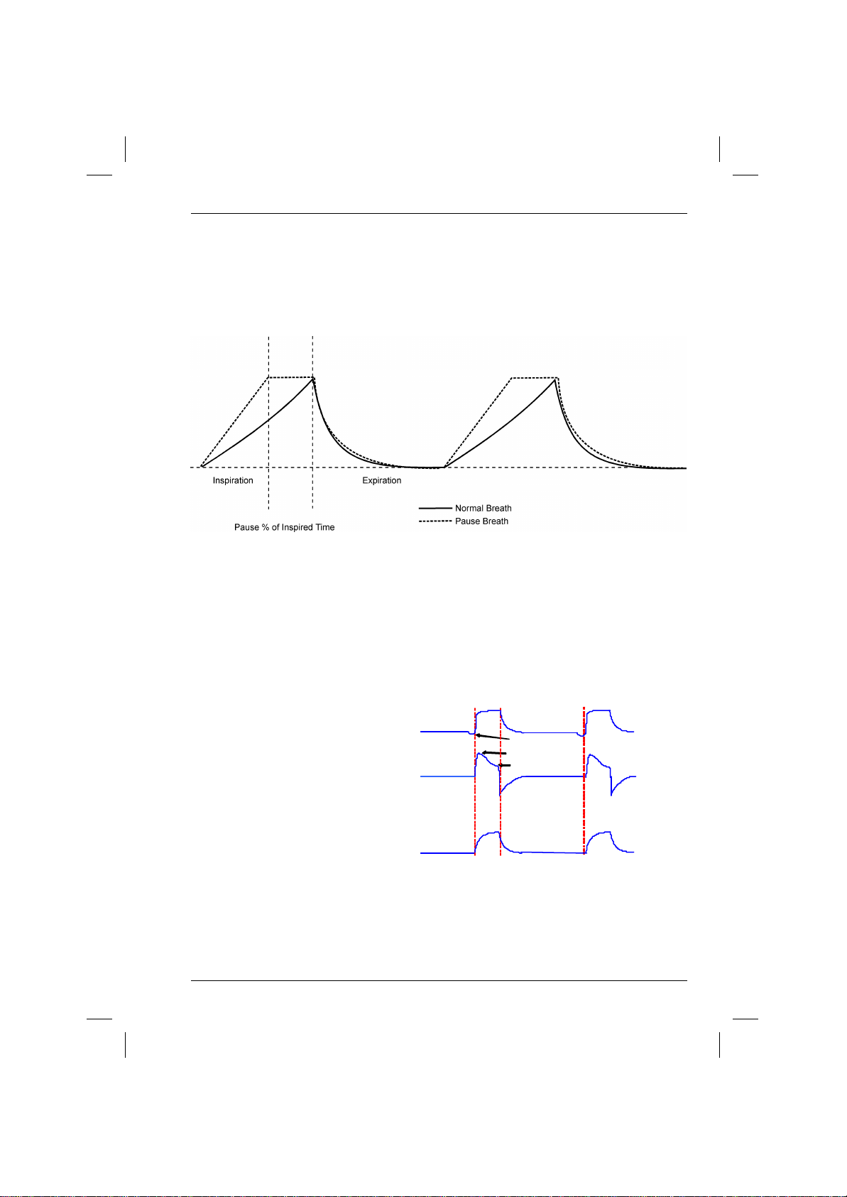
1.3.3.5 Inspiratory Pause
When pause is activated, a percentage of the inspiratory time is used as a plateau
prior to the start of the expiratory phase. This means that the I:E ratio is
maintained irrespective of the duration of the pause. The pause feature is found
under the Mode Selection menu and is user selectable from 0-50%.
1.3.3.6 Sigh
When Sigh is activated, the delivered tidal volume in Volume Control Mode is
increased by the set percentage of the duration of one breath at the set
frequency. The default percentage is 10% and default frequency is once every
tenth breath.
1.3.3.7 Pressure Support
In Pressure Support mode the
patient controls when the ventilator
starts to deliver and when the
ventilator cycles into expiration.
The start in inspiration is set by the
flow trigger, once the patient has
made an attempt to breathe that
exceeds the set flow trigger the
ventilator will deliver at the support
pressure until the flow is reduced to
25% of the peak flow. The ventilator will then go into expiration.
In Pressure mode bpm, tidal volume and I:E ratio are all monitored values.
700/900 Series Ventilators User Manual 19
PS + PEEP
PEEP
Trigger
Peak Flow (up to 100 LPM)
Insp.
Exp. Theshold (25%)
Exp.
Pressure
Flow
Volume
Page 21

1. Description
Section 1 - 700/900 Series Ventilators
1.3.4 Principles of Operation
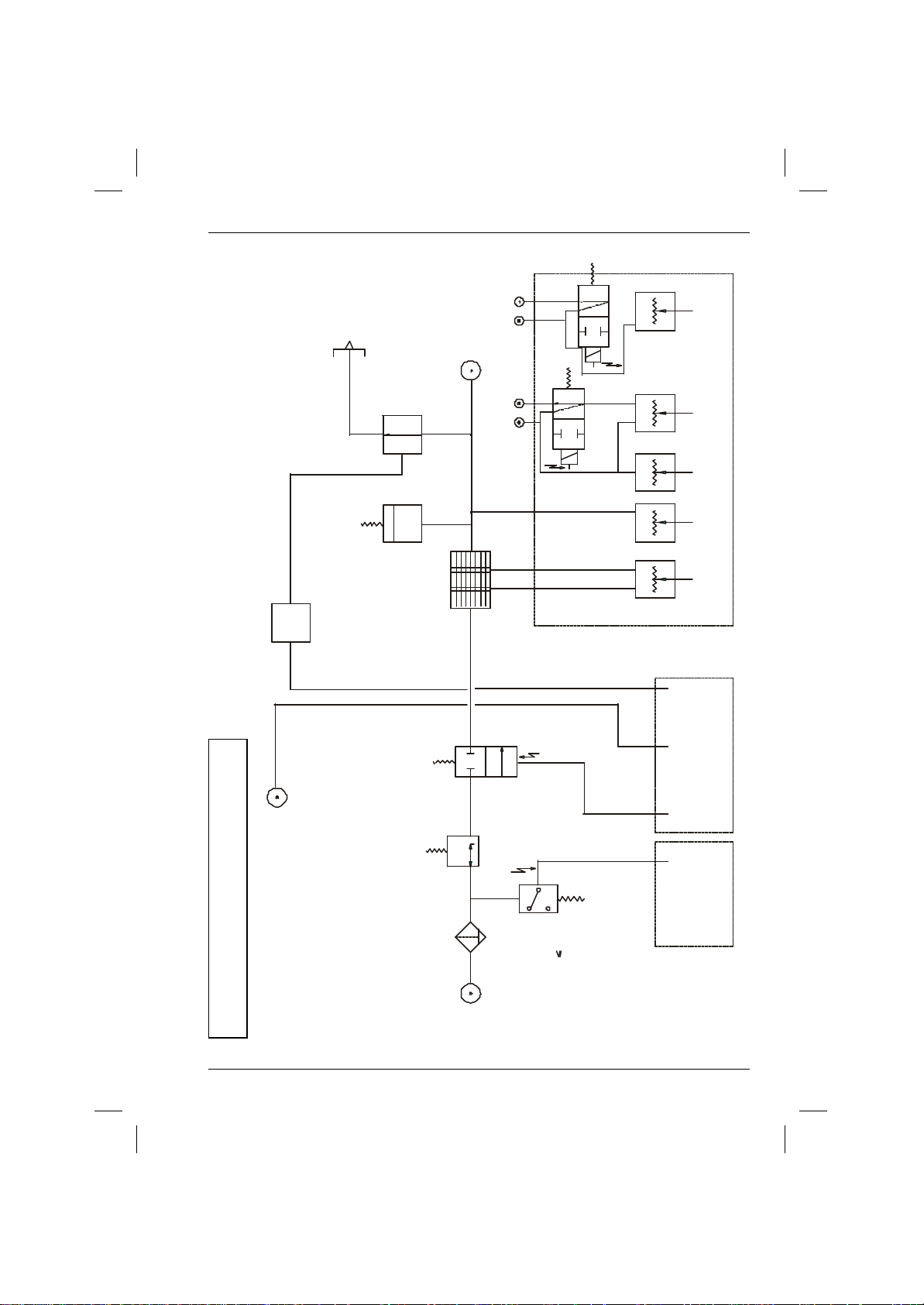
For active inspiration, the flow control valve is opened to provide a specific gas
flow into the bellows assembly. Simultaneously the expiratory solenoid closes and
pressure is generated in the bellows assembly producing an inspiratory flow to
the patient.
The flow and pressure are measured and monitored by the microprocessor
feedback system.
Expiration occurs when the flow control valve is closed and the expiratory
solenoid opens and releases the gas from the bellows assembly.
In Pressure Control Mode the set pressure is achieved during inspiration and
maintained at that level by allowing a controlled bypass through the expiratory
valve. This allows the required pressure level to be maintained whilst
compensating for any fresh gas flow into the patient circuit.
For expiration the expiratory solenoid is opened which releases the gas from the
bellows assembly.
During all modes of ventilation an autozero is periodically applied to the flow
sensors just prior to a breath being delivered; at this point there is no flow
through the sensors, this ensures that the measured values are maintained as
accurately as possible regardless of environmental variations.
20
700/900 Series Ventilators User Manual
Page 22
AUTO ZERO VALVE
AUTO ZERO VALVE
PRESSURE INTERFACE BOARD
Section 1 - 700/900 Series Ventilators
1. Description
INSP
CONTROL
BOARD
EXHAUST
PORT
75cmH2O
RELIEF
SOLENOID
VALVE
EXPIRATORY
VALVE
PORT
OUTLET
GAS
DRIVE
FRESH GAS
AIRWAY FLOW
PNEUMOTACHOGRAPH
SENSOR INLET
SENSOR INLET
PT1PT3
PT5
PT4
PT2
DUMP
PEEP
PL5
VALVE
VALVE
GAS FLOW
FRESH
AIRWAY FLOW
PATIENT
PRESSURE
PATIENT
PRESSUREFLOW
DRIVE
INSPIRATORY
FLOW CONTROL VALVE
PEEP
VALVE
SOCKET
34.5 psi
Figure 2 Pneumatic System
GAS
INLET
SUPPLY
MAIN
FILTER
2.5-7 BAR
36-101 psi
REGULATOR
LOW
PRESSURE
SUPPLY
36psi
DETECTOR
PL4 PL8
FLOW
VALVES
PL5
SWITCH
PRESSURE
POWER SUPPLY BOARDCONTROLLER BOARD
700/900 Series Ventilators User Manual 21
Page 23

1. Description
Section 1 - 700/900 Series Ventilators
1.3.5 Parameters
The following parameters can be set and/or monitored when the ventilator is in
operation.
1.3.5.1 PEEP
The 700/900 series ventilator
continuously monitors and
PEEP
(
cmH2O)
P
displays the Positive End
Expiratory Pressure (PEEP). By
default, a PEEP of 2 - 4 cm H
introduced to the circuit, caused
by the bellows assembly, which is
shown as OFF. A PEEP value
between 3 and 20 cm H
set from the panel, with an
automatic alarm of more than
25% above the set value.
A minimum difference of 8 cm
H
O in adult and 5 cm H2O in ped
2
is enforced between the set PEEP
O is
2
O can be
2
PEEP OFF
(Resident PEEP
2-4 cmH2O )
MIN 8cmH2O (Adult)
5cmH2O (paed)
P(
cmH2O)
Pressu re Control
SET PEEP
(3-20cmH2O)
O
T
T
level and the pressure controls shown below.
MODE PRESSURE CONTROL
Volume Control Pressure Limit
Pressure Control Set Pressure
Pressure Support Support Pressure
SIMV + PSV Support Pressure + Pressure Limit
When the user changes a value such that it does not comply with the required
difference the box surrounding the feature being adjusted and the value of the
feature causing limiting to be enforced is highlighted red. The value being
adjusted could either be the PEEP level or the relevant pressure control.
The user can then:
• Accept the value being adjusted, in which case it will be set to the nearest
acceptable value.
• Adjust the value to a non-conflicting value.
If the user does not make the change before end of time allowed for adjustment
the value will set to the nearest acceptable value.
22
700/900 Series Ventilators User Manual
Page 24

Section 1 - 700/900 Series Ventilators
1. Description
1.3.5.2 Trigger
The level of negative flow caused by the patient's attempt to breathe before the
ventilator initiates flow to assist the patient with the spontaneous breath.
Range 5 to 15 L/min all modes (SIMV + PSV and Pressure Support).
1.3.5.3 Support Pressure
Breathing circuit pressure level for assistance with patient's spontaneous breath.
Range 5 cm H2O to 30 cm H2O SIMV + PSV and Pressure Support (PEEP
referenced).
1.3.5.4 Fresh Gas Compensation
0 l/m to 30 l/m of fresh gas can be compensated for and displayed on screen.
1.3.5.5 Oxygen
A fuel cell sensor can be connected to allow monitoring of 0% to 100% O2, with
alarms of 18% to 110%. The sensor can be calibrated
1.3.5.6 Tidal Volume
Volume to be delivered by the ventilator in each breath.
Range 20 ml to 1500 ml all modes.
1.3.5.7 Minute Volume
Measured volume delivered by the ventilator per minute.
Range 0.3 l/m to 25 l/m all modes.
1.3.5.8 Expired Tidal volume
Expired tidal volume is measured by the sensor in the breathing circuit, in either
mechanical ventilator spontaneous breathing mode. The measured value is
displayed in the tidal volume window.
1.3.5.9 BPM (Frequency Control)
The mechanical frequency of the ventilator in breaths per minute (BPM).
700/900 Series Ventilators User Manual 23
Page 25

1. Description
Section 1 - 700/900 Series Ventilators
1.3.5.10 I:E Ratio
The ratio of the inspiratory time to the expiratory time.
Range 2.0:1 to 1:5.0 all modes.
1.3.5.11 Pressure Limit
The breathing system maximum pressure limit.
Range 10 cm H2O to 50 cm H2O Paed.
10 cm H2O to 70 cm H2O Adult.
1.3.5.12 Peak Pressure
Range 0 cm H2O to 100 cm H2O
1.3.5.13 Mean Pressure
Range 0 cm H2O to 100 cm H2O
1.3.5.14 Compliance
System compliance in ml/ cm H2O
Patient compliance in ml/ cm H2O
24
700/900 Series Ventilators User Manual
Page 26
Section 1- 700/900 Series Ventilators
1. Description
1.4 User Interface
1.4.1 Front Panel
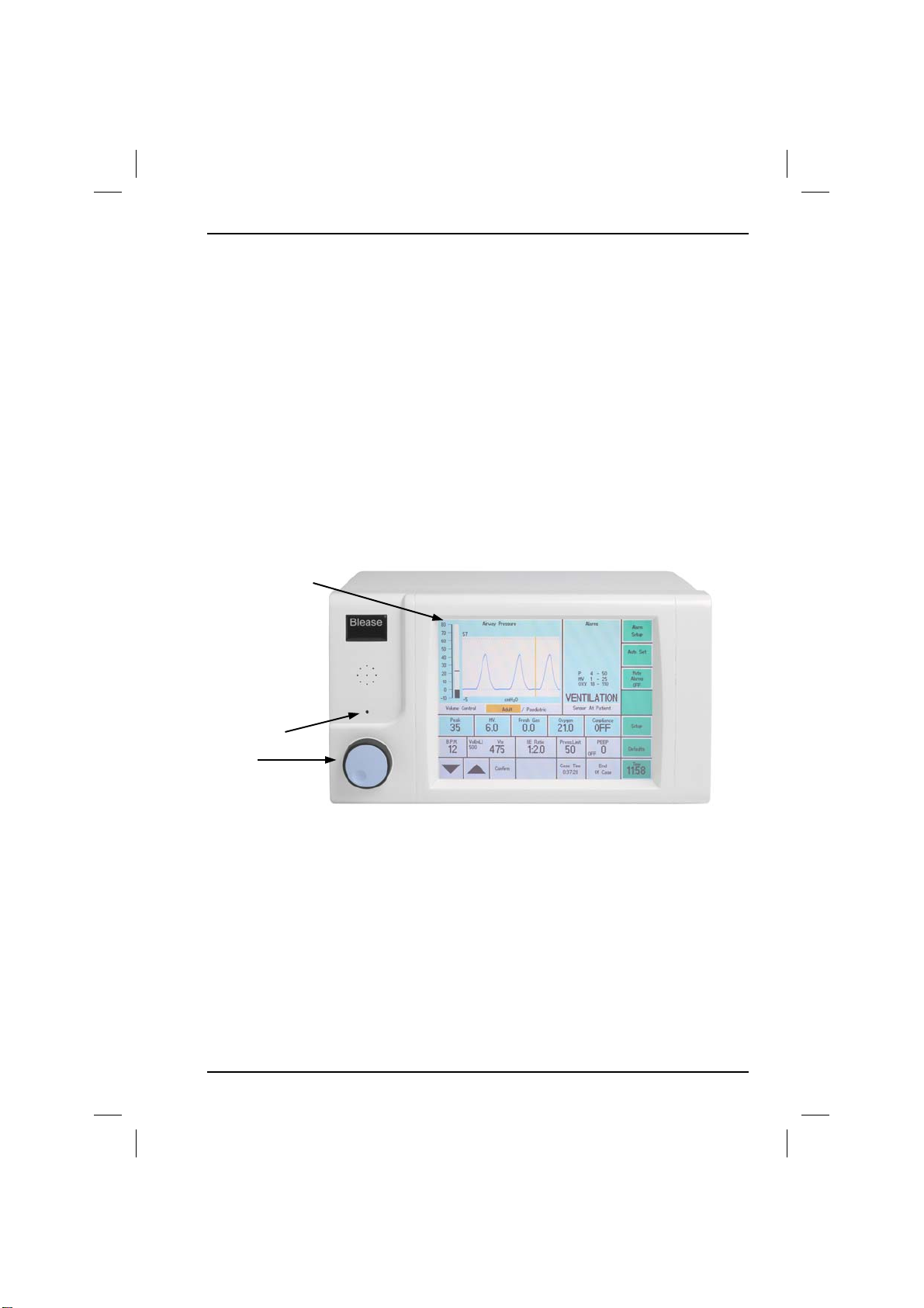
The front panel of the 700/900 series ventilator has the following controls and
indicators:
1 LCD Touch Screen (700 monochrome, 900 Color)
2 Battery-Status LEDs
3 Trak Wheel
1
2
3
Figure 3 Front Panel
700/900 Series Ventilators User Manual 25
Page 27
1. Description
Section 1 - 700/900 Series Ventilators
1.4.1.1 Normal Screen
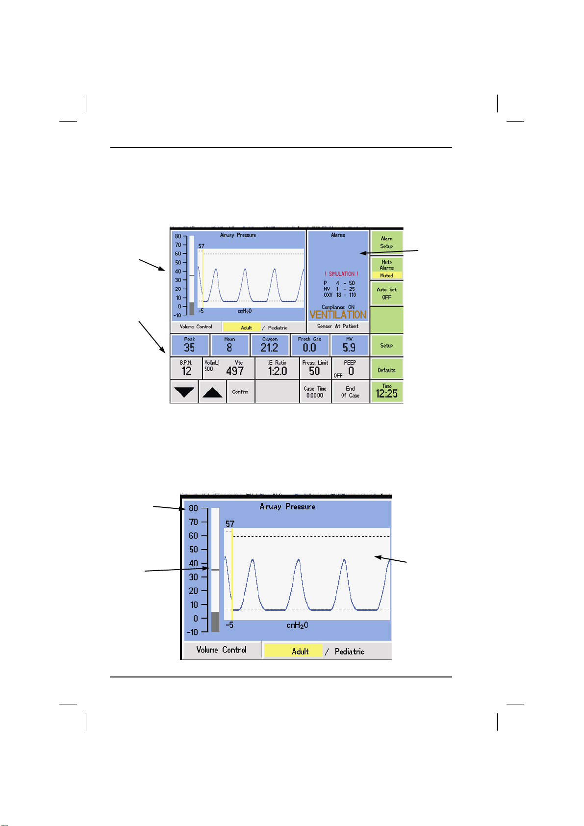
The normal screen is divided into three display areas: Activity, Alarms and
Parameters.
Activity
Parameters
1.4.1.2 Activity Display Area
The activity area includes a graphical display updated in real time to show the
breathing cycle. The graph is auto-scaled to fit on the y-axis and to show three
cycles on the x-axis.
Status Line
Alarms
Peak
Marker
26
Graphical
Display
700/900 Series Ventilators User Manual
Page 28
Section 1 - 700/900 Series Ventilators
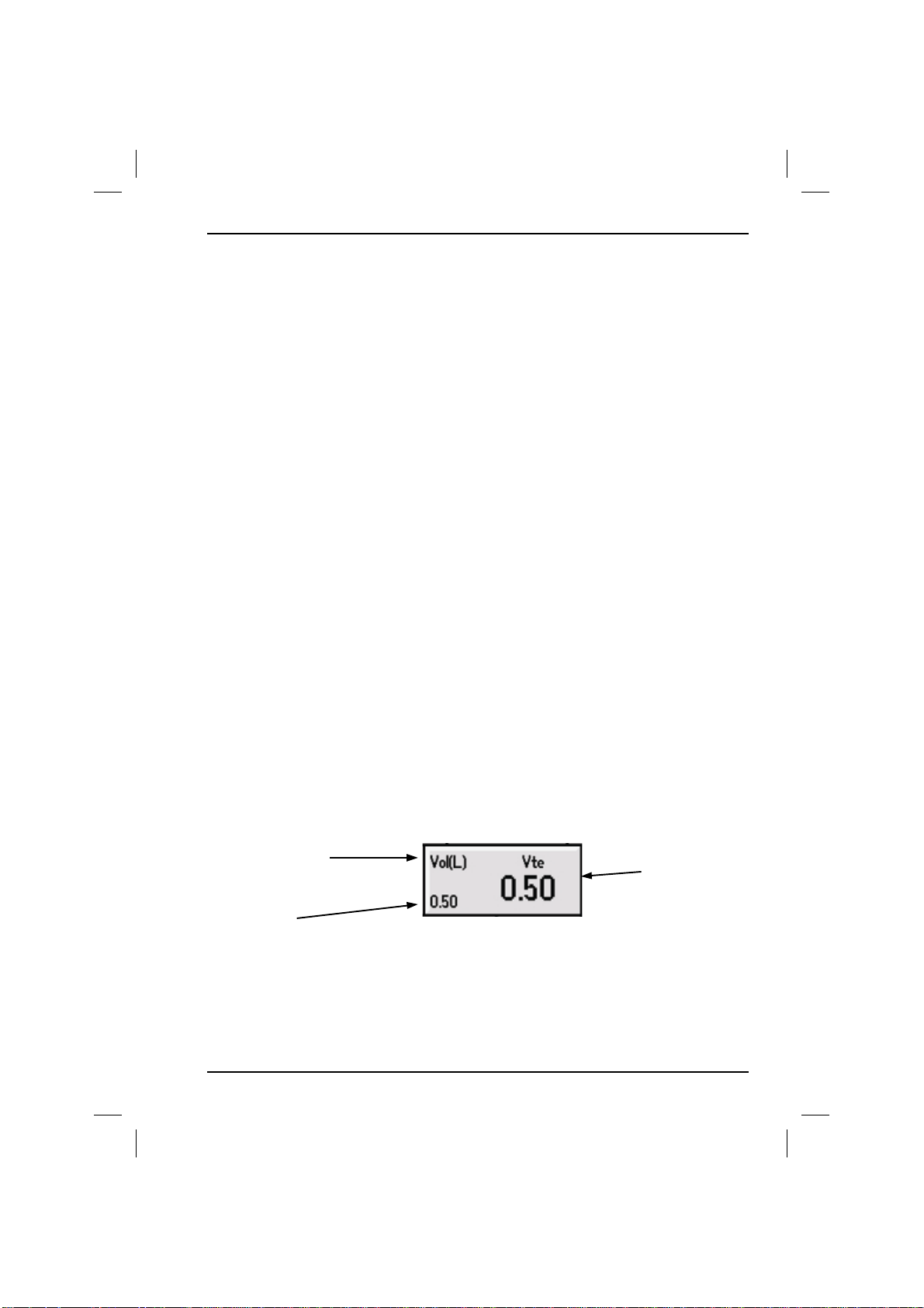
Below the waveform, the status line shows:
• the current ventilator mode (Volume Control, Pressure Control, Pressure
Support or SIMV + PSV);
• Adult or Ped mode;
• Pause (when selected);
• Sigh (when selected).
1. Description
1.4.1.3 Alarms Display Area
The alarm display lists any active alarms, with the most recent at the top of the
list. The alarm settings for the current mode of operation are shown at the
bottom of the alarm display area.
1.4.1.4 Parameter Display Area
The parameters display comprises of an array of windows, each of which displays
a parameter that has been selected for monitoring, or a level that has been set
for the current function.
If a parameter has a pre-set level, as well as a monitored value, the pre-set level is
indicated at the bottom left of the parameter window and the monitored value is
shown in the larger font to the right of the window.
Parameter
Pre-set
Level
700/900 Series Ventilators User Manual 27
Monitored
Value
Page 29

1. Description
Section 1 - 700/900 Series Ventilators
1.4.1.5 Trak Wheel & Touch Screen
The Trak Wheel is a rotary encoder, incorporating a switch, which functions in a
similar way to a computer mouse when turned left or right. It allows control of
the on-screen cursor and the option to vary numerical data.
1.4.1.5.1 Trak Wheel
Selecting a Parameter
1. Turn the Trak Wheel in either direction until the required parameter is
highlighted.
2. Press the Trak Wheel to select the item.
The selection is cancelled if the Trak wheel is not moved for
approximately 5 seconds.
Editing a Parameter
1. When a parameter is selected, turn the Trak Wheel clockwise to increase
the numerical value or anticlockwise to decrease the value.
2. Press the Trak Wheel when the required value is displayed to confirm
selection.
Selecting a Menu Item
1. Within a menu, turn the Trak Wheel clockwise to descend the menu or
anticlockwise to ascend the menu. If a menu item is displayed in white, it is
not selectable at this time.
2. Press the Trak Wheel to confirm selection.
User adjustable parameters can be set from the normal screen:
1. Turn the Trak Wheel until the desired parameter is highlighted. When the
cursor reaches the end of one row it will move to the other.
2. Press the Trak Wheel. The parameter is highlighted, indicating that it can be
edited.
3. Rotate the Trak Wheel until the required value is indicated.
4. Press the Trak Wheel again to confirm the new value.
28
700/900 Series Ventilators User Manual
Page 30

Section 1 - 700/900 Series Ventilators
1. Description
1.4.1.5.2 Touchscreen
Setting Parameter
Be sure to use your fingertip to activate the touchscreen, do not use pens or
pencils or any other sharp instruments as these will damage the touchscreen.
• Touch box for the parameter you want to change.
• The up and down and confirm buttons are now active.
• Press up or down button until you have the desired setting.
• Press confirm to confirm setting.
To change settings.
• Menu keys on the right of the screen
• Press appropriate setup or alarm button
• Another menu box will appear
• Select parameter
• Press return until normal screen is restored.
Note If confirm button is not pressed the old value will be restored.
Combination of both touchscreen and trakwheel can be used.
700/900 Series Ventilators User Manual 29
Page 31

1. Description
1.4.2 Battery Status LEDs
Icon Color Function
Section 1 - 700/900 Series Ventilators
RED
AMBER
GREEN
Mains Failure - the mains power supply has failed
and the ventilator is running from its internal
battery.
Battery Low - the battery is running low and the
mains supply should be connected to recharge the
battery immediately.
Battery Charging - the mains power supply is
available and the battery is charging.
This indicator glows green when the ventilator is
switched on.
To preserve battery life, never store the ventilator with its
battery discharged, Do not store the ventilator in close
proximity to heat sources of any kind.
30
700/900 Series Ventilators User Manual
Page 32
Section 1 - 700/900 Series Ventilators
1. Description
SETUP
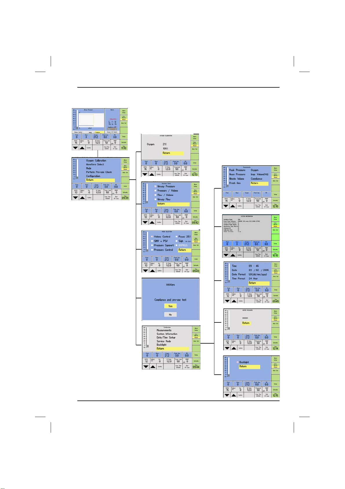
1.4.3 Menu Tree
1.4.3.1 Setup Menu
OXYGEN CALIBRATION
MEASUREMENTS
WAVEFORM SELECT
SYSTEM INFORMATION
MODE
DATE/TIME SETUP
PRE-USE PERFORM CHECK
SERVICE MODE
CONFIGURATION
BACKLIGHT
700/900 Series Ventilators User Manual 31
Page 33
Section 1 - 700/900 Series Ventilators
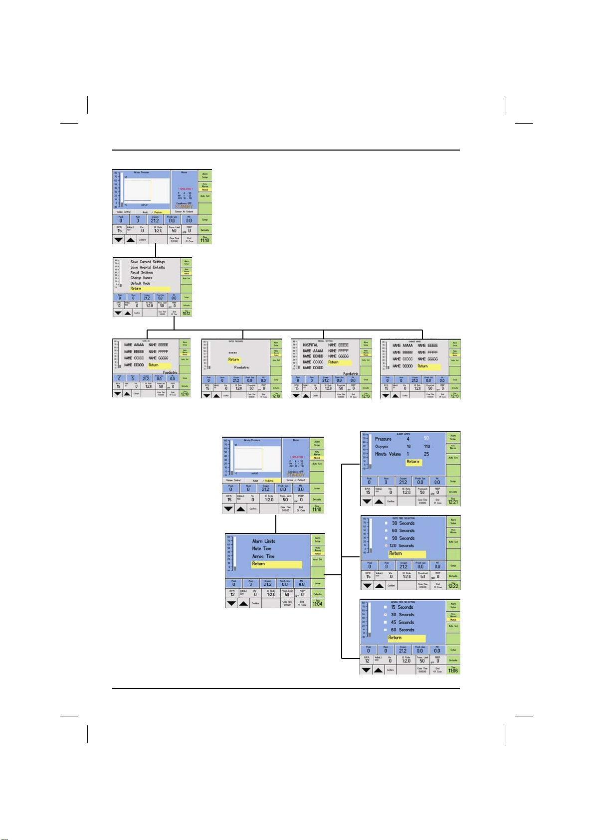
DEFAULTS
1.4.3.2 Defaults Menu
SAVE CURRENT SETTINGS SAVE HOSP DEFAULTS RECALL CHANGE NAMES
1.4.3.3 Alarm Setup
32
ALARM SETUP
ALARM LIMITS
MUTE TIME
APNEA TIME
700/900 Series Ventilators User Manual
Page 34

Section 2 - 700/900 Series Ventilators
2. Operation
2. Using the Ventilator
This section describes how to:
• switch on the ventilator;
• select the operating mode and functions;
• set the operating parameters.
WARNING: Short inspiratory times may result in inconsistent breath delivery.
Avoid control combinations which may produce very short inspiratory times
(<150 ms).
WARNING: Pressure limiting is a safety feature and is also used in adult and
pediatric mode to provide ventilation (Pressure Control). It should not be used
for any other purpose, such as creation of micro-breaths or emulation of
specialized high frequency/low volume ventilation systems, otherwise injury to
the patient may result.
WARNING: Patient circuit disconnection is a hazard to the patient. Take extreme
care to prevent such an occurrence.
Monitored values require a few minutes to stabilize after initial activation.
Despite this, the ventilator and set values will function correctly.
2.1 Operation
2.1.1 Powering Up the Ventilator
To power up the 700/900 series ventilator Press and Hold the trakwheel for four
seconds. The screen will then turn ON and give access to the pre-use test. The
ventilator powers up in Standby with monitoring in standby.
2.1.2 Starting the Ventilator
The ventilator is started by selecting the Run/Standby button on screen.
2.1.3 Stopping the Ventilator
The ventilator is stopped by selecting the Run/standby button on screen.
2.1.4 Activating and monitoring alarms
Monitoring and monitoring alarms are activated with breath
detection.
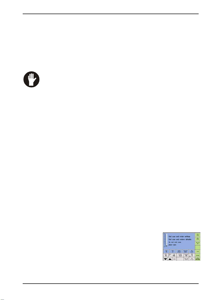
2.1.5 End of Case
With the ventilator stopped and in bag mode the end of case
button is active. With selection of end of case the options
shown on following screen diagram are available.
2.1.6 Powering down the Ventilator
To power down the 700/900 series ventilator select End of case button on the
screen. One of the options is to power down. Select Yes to the question ‘power
down YES or NO’. The ventilator will then turn OFF.
SA
700/900 Series Ventilators User Manual 33
Page 35
2. Operation Section 2 - 700/900 Series Ventilators
2. Using the Ventilator
This section describes how to:
• switch on the ventilator;
• select the operating mode and functions;
• set the operating parameters.
WARNING: Short inspiratory times may result in inconsistent breath delivery.
Avoid control combinations which may produce very short inspiratory times
(<150 ms).
WARNING: Pressure limiting is a safety feature and is also used in adult and
pediatric mode to provide ventilation (Pressure Control). It should not be used
for any other purpose, such as creation of micro-breaths or emulation of
specialized high frequency/low volume ventilation systems, otherwise injury to
the patient may result.
WARNING: Patient circuit disconnection is a hazard to the patient. Take extreme
care to prevent such an occurrence.
Monitored values require a few minutes to stabilize after initial activation.
Despite this, the ventilator and set values will function correctly.
Powering Up the Ventilator
To power up the 700/900 series ventilator fitted to the Sirius, turn the gas supply
switch on (clockwise) on the Sirius trolley. The screen will then turn ON and give
access to the pre-use test. The ventilator powers up in Standby with monitoring
in standby.
Starting the Ventilator
The ventilator is started by turning the BAG/VENT switch to VENT on the
absorber.
Stopping the Ventilator
The ventilator is stopped by turning the BAG/VENT switch to BAG on the
absorber.
Activating and monitoring alarms
Monitoring and monitoring alarms are activated with breath detection.
End of Case
With the ventilator stopped and in bag mode the end of case
button is active. With selection of end of case the options
shown on following screen diagram are available.
Powering down the Ventilator
To power down the 700/900 series ventilator turn the gas
supply switch to OFF (anticlockwise). The ventilator will then turn OFF.
SIR
700/900 Series Ventilators User Manual
33
Page 36
2. Operation
Section 2 - 700/900 Series Ventilators
2.2 Pre-use Testing
Please read the following instructions in conjunction with the
information on Compliance compensation contained in the
Installation section of this manual.
The patient airway flow sensor head must be in the patient circuit in
order to carry out compliance compensation.
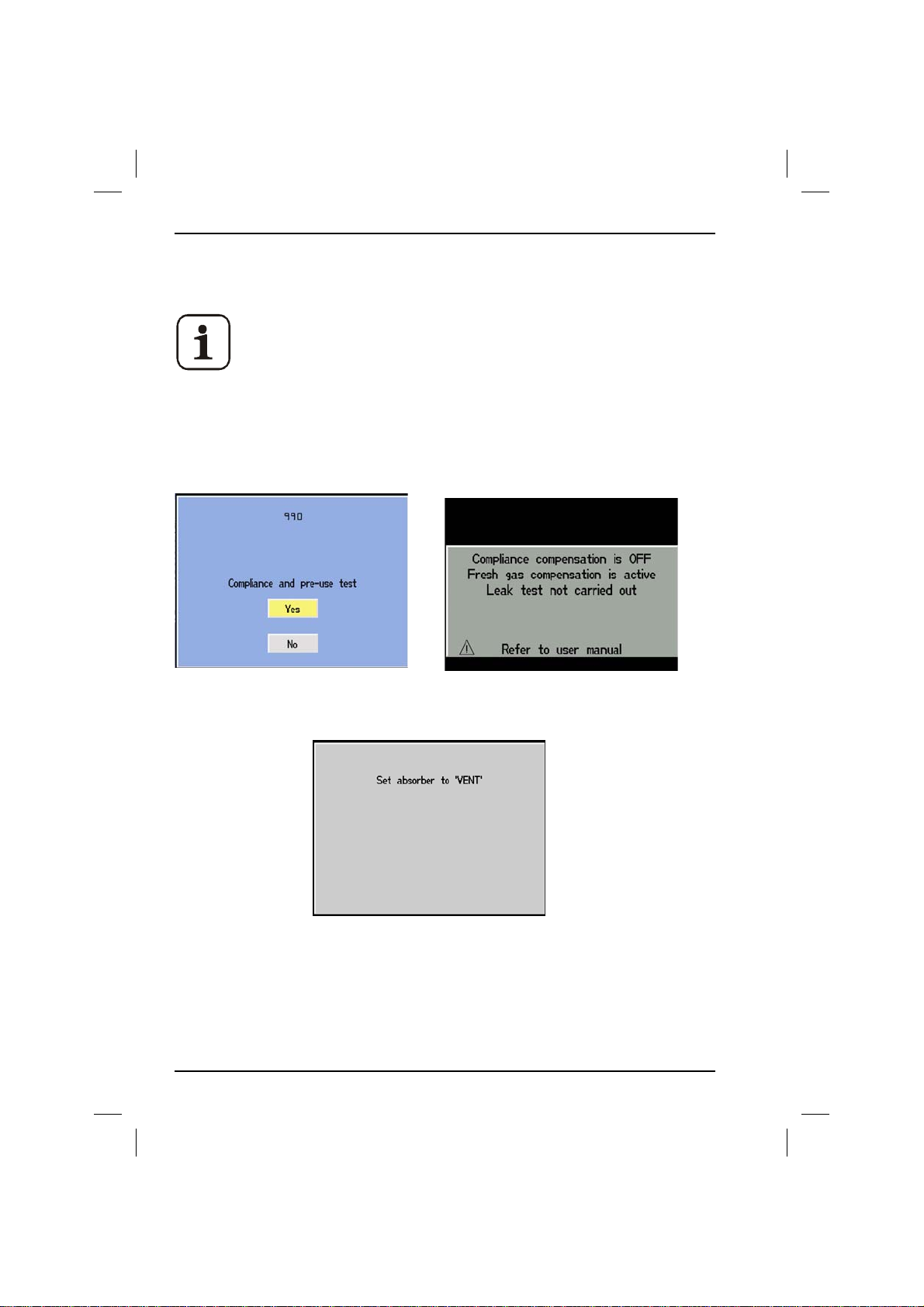
The option to run a Pre-Use Test for Compliance Compensation is built into the
Startup menu. (model numbers shown on screens would be different dependant
on configuration).
The opening screen at switch on.
Following YES this is the start screen for the pre-use tests. Follow all on screen
34
The warning screen if the pre-use is
cancelled.
instructions.
700/900 Series Ventilators User Manual
Page 37
Section 2 - 700/900 Series Ventilators
2. Operation
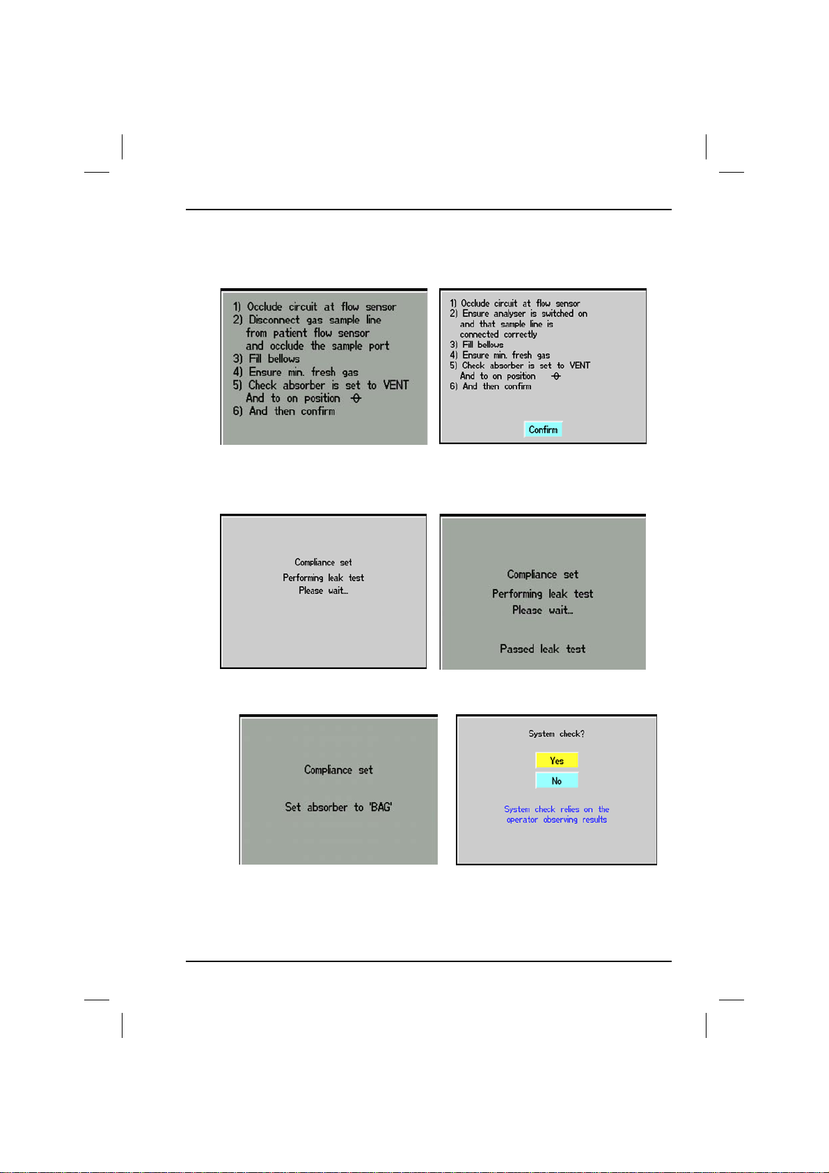
At this stage 1 of 2 screens may appear depending on how the gas analyzer is
set-up. The left screen is if the analyzer is scavenged or the right screen if the
analyzer exhaust is returned to the circle.
The instructions given are the preparation for performing 3 ventilator tests.
1. PEEP Valve calibration, 2. Calculation of system dead space (compliance), 3. Leak Test.
Having calibrated the PEEP valve and measured the dead space the leak test starts
on the left and concludes with the right hand screen after 20 seconds.
Having successfully passed the leak test the option is given to test the Manual or
Bag system of ventilation. Making a no decision at this point will enter the
normal run screen. Yes will follow on to the preparation for system test.
700/900 Series Ventilators User Manual 35
Page 38
2. Operation
Section 2 - 700/900 Series Ventilators
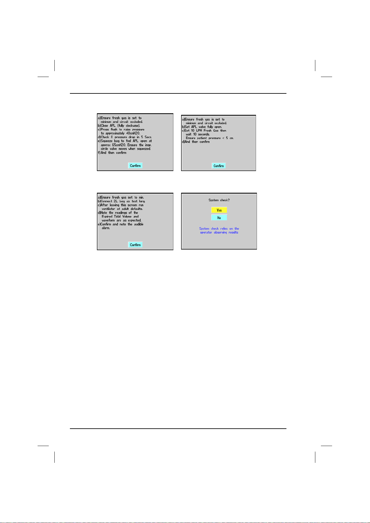
The following 3 screens are the Gas Machine Tests.
NB. This is just a set of instructions it is not an active test. Set the controls as instructed and
carry out the manual test as instructed making the necessary observations that all is working as
correctly.
Having proved that the manual system works the ventilator can be tested at
nominal settings of TV 500 mL, 12 BPM, I:E 1:2.0 Set up the system as described
Press the track wheel when ready and set the Bag/Vent switch to Vent. Ensure
that the Bag and Bellows are full. Observe the displayed wave form and expired
volume are consistent with the expected result. Other tests can be carried out at
the users discretion.
When this test is completed satisfactorily the system is ready for use.
If the optional external PEEP valve is tested during the Pre-Use test. If the valve is
replaced or fitted during use the Pre-Use test must be carried out to ensure
continued accurate operation.
36
700/900 Series Ventilators User Manual
Page 39
Section 2 - 700/900 Series Ventilators
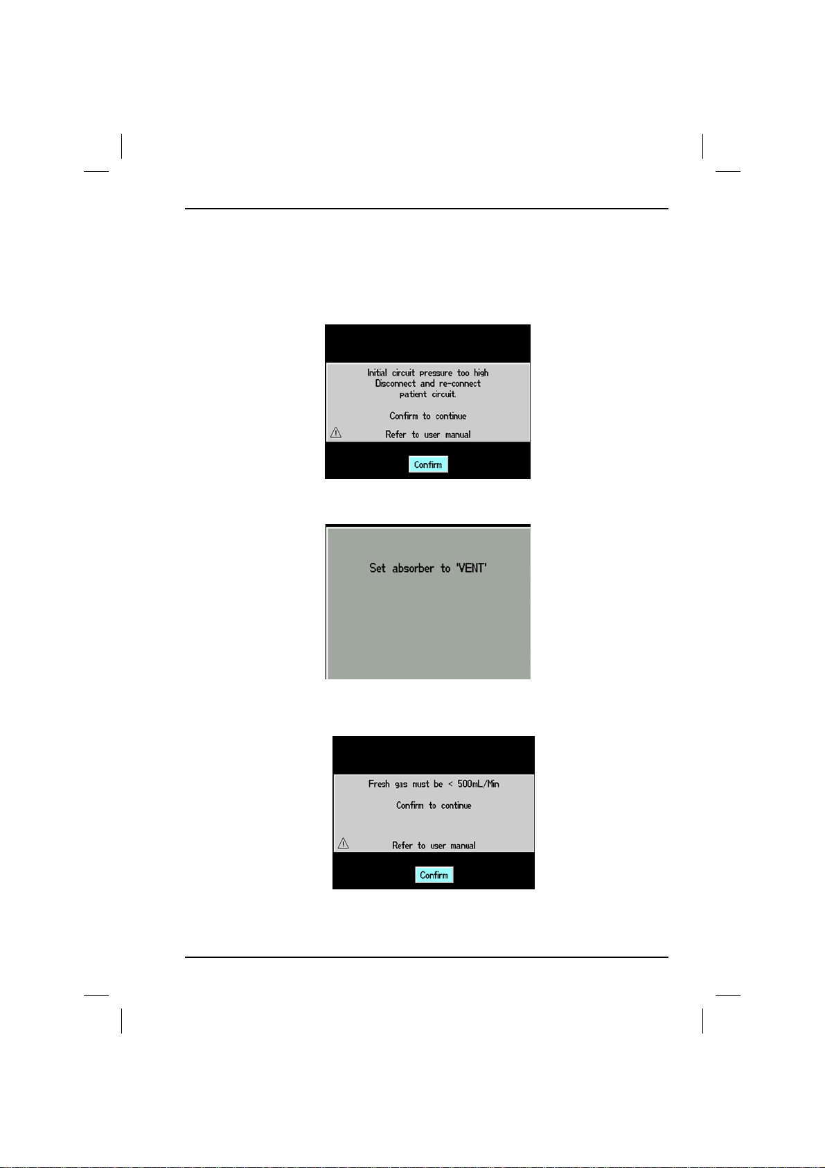
2.2.1 Pre-use Test Error Messages
If errors are encountered during the pre-use test then one of the following
screens will be displayed. The screens are designed to give an indication of what
may have caused the error and possible solution.
This screen suggests that the patient pressure is too high (>4cmH2O) to begin the
test.
2. Operation
If the absorber is not set to Vent when starting the test the system will give a
reminder.
Fresh Gas too High. Reduce and Re-Start.
700/900 Series Ventilators User Manual 37
Page 40

2. Operation
Pull forwards a couple of cm,
check no foreign objects are
between the absorber and main
frame, push absorber fully back.
Section 2 - 700/900 Series Ventilators
Check the gauges for correct gas
supply.
Failure to fill the bellows at the
start of the tests will be
NB. It has been noted that this can be caused by fitting a Re-Breathing bag to the “Y”
connector instead of occluding the circuit on the plug provided on the absorber.
If the system has a leak that is
too large or if the circuit is not
occluded correctly the test will
fail at this point.
If a leak is detected the above causes are the possible places to look. It should be
noted that these are not the only leak possibilities, small holes in the sensor
tubing, Cracks in Breathing circuits are sometimes possibilities too.
38
700/900 Series Ventilators User Manual
Page 41
Section 2 - 700/900 Series Ventilators
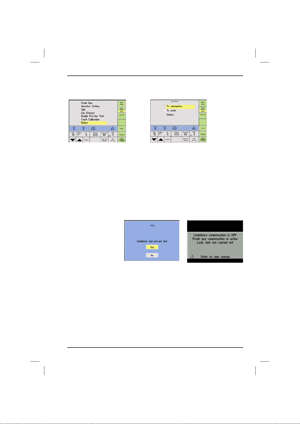
Below are the screens that set-up the conditions affecting the opening Pre-use
screens regarding gas analyzer exhaust positioning.
2. Operation
The gas analyzer exhaust gas can be dealt with in two ways a) it can be simply
exhausted to atmosphere (scavenged) or b) it may be returned to the circle.
These choices need to made by the hospital and the selection made at the time
of commissioning the system. The selection can have marked effects on he leak
tests carried out during the pre-use testing.
If the sample line is disconnected but the exhaust is returned to the circle then it
may mask leaks by providing an additional gas input. If the reverse situation I.e.
the sample line is connected but the exhaust is not then it would constitute a
leak.
2.2.2 Compliance test skipped
If the operator chooses
not to carry out a
compliance pre-use test'
the information below
will be displayed on
screen.
The opening screen.
2.2.3 Fresh Gas
Fresh Gas Flow Compensation has several effects on the operation of the
ventilator. In normal conditions the volume added to each breath due to fresh
gas flow / time is deducted from the driving gas volume that is used to compress
the bellows, this gives a volume at the "Y" piece that is constant.
In some situations when the normal correction cannot be completed an alarm
will be caused and advice given as to what to do when correction cannot be
made by reducing drive gas.
700/900 Series Ventilators User Manual 39
The warning screen that
proceeds if the pre-use
is cancelled.
Page 42
2. Operation
Section 2 - 700/900 Series Ventilators
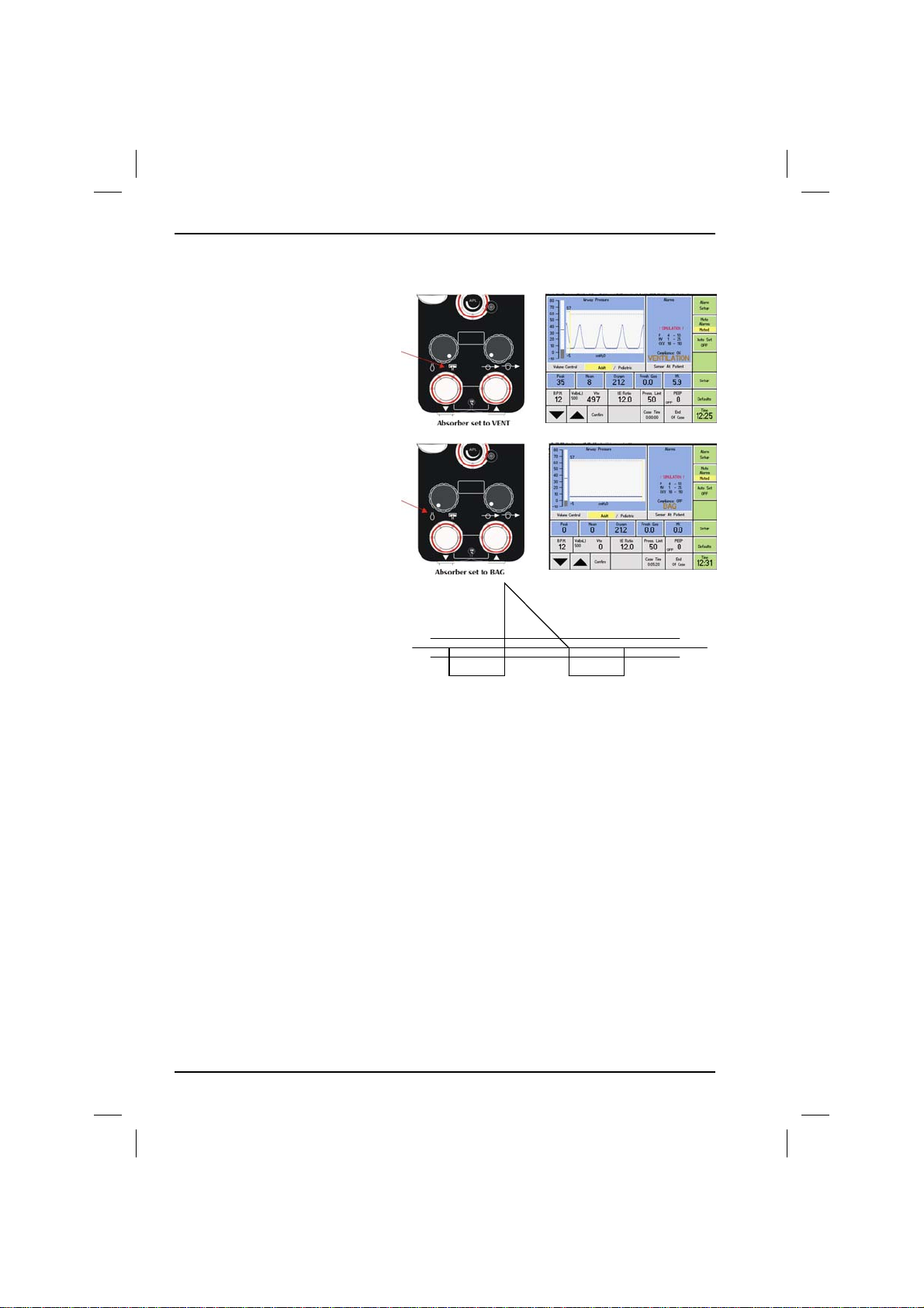
2.2.4 Standby/Bag/
Run
By turning the absorber to VENT
the ventilator will automatically
run.
By returning switch to BAG the
ventilator will go into BAG mode.
The diagram shows a breath as
flow into and away from the
patient
The Breath is detected when:-
• Inspired is passing down thro -2LPM
• Expiration is when passing from -2LPM and up thro +2LPM
• The breath ends when the next transition is made thro +2LPM and down to -2LPM
• The breathing detection that activates “Bag Mode” is after 3 such transitions has taken
place in <30 seconds
After a breathing pattern is detected the Apnoea detector is made active. This will detect a
failure to breath after the user set period.
The ventilator in STANDBY will on detecting a spontaneously breathing patient switch to
BAG mode and STANDBY on screen will be replaced by the word “BAG”. In this condition
all relevant alarms will be active.
The alarms not in use at this time are:
• Pressure Low
• MV Low
The system will when set to RUN change the on screen display to VENTILATION and
operate as the selected mode.
Expiration
Inspiration
+2LPM
-2LPM
40
700/900 Series Ventilators User Manual
Page 43
Section 2 - 700/900 Series Ventilators
Whilst in BAG mode all monitoring is still active and
alarms are active with the exception of low/high MV,
low/high BPM and PEEP alarms.
To cancel these and return to Standby mode press End
of Case button on screen and then select an option.
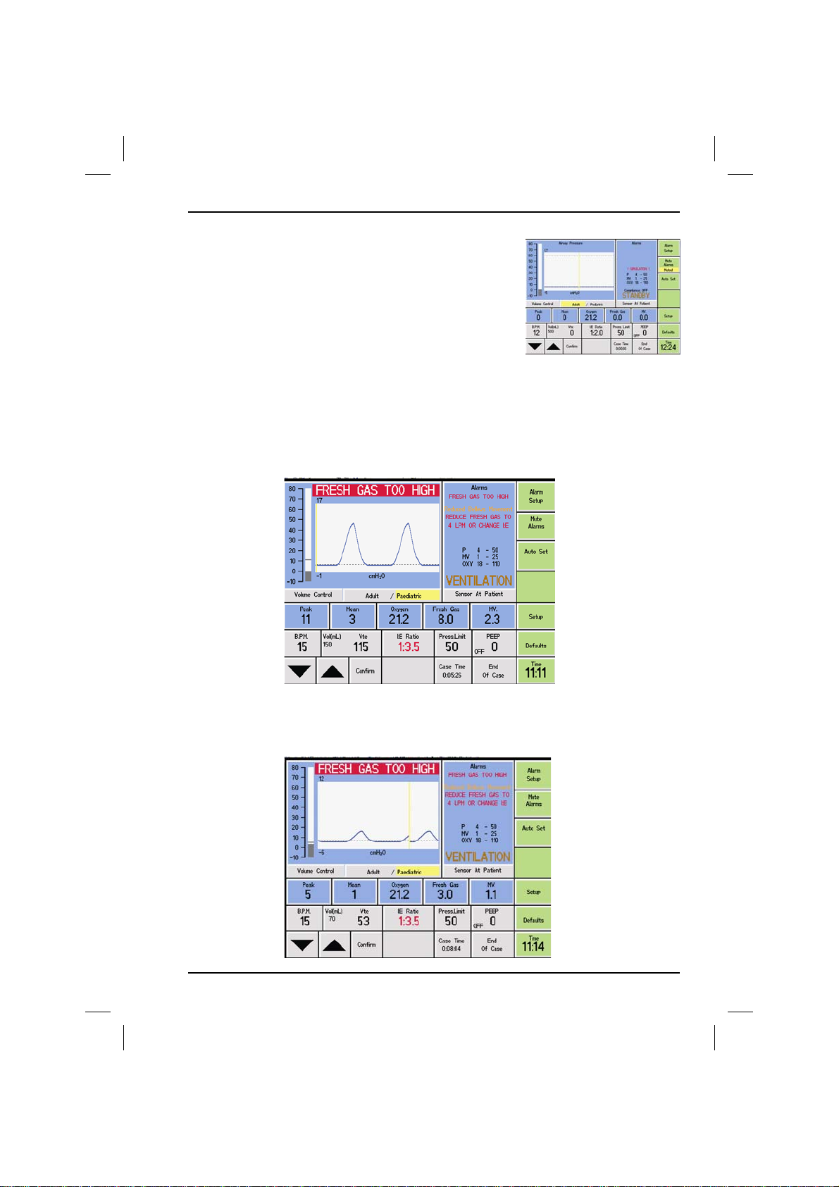
The following is a summary of the alarm messages, under various conditions.
The ‘normal’ situation at mid-high tidal volumes is that there will be the option to
change either I:E or fresh gas. The I:E is highlighted in red, and the value to set
the fresh gas to is displayed in the alarm panel (i.e. in this case 10 LPM).
2. Operation
If the tidal volumes are low, the allowable fresh gas flow will be low, and where
the suggested calculated fresh gas flow would be less than 2 LPM, the ventilator
would say “Reduce Fresh Gas”.
700/900 Series Ventilators User Manual 41
Page 44
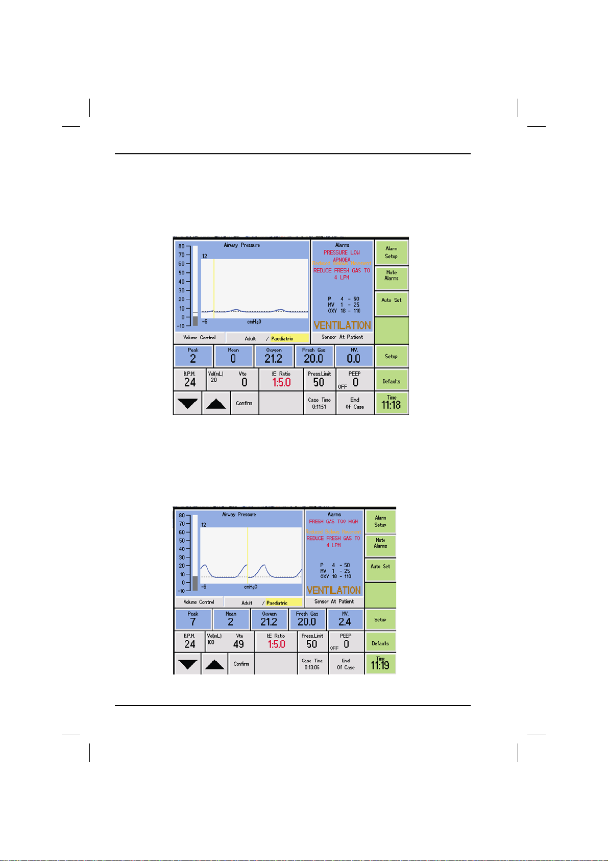
2. Operation
In some cases, at high fresh gas flow, the calculated I:E would be outside the
range of I:E settable on the ventilator. The maximum I:E settable on the ventilator
is 1:5.0. i.e. if calculated I:E should be 1:7 which is not possible. Then the only
option is to reduce the fresh gas flow. Thus the I:E will NOT be forced red, and
will be left at it’s set value.
Section 2 - 700/900 Series Ventilators
2.2.5 I:E Setting
In the case where the I:E is forced to a value in RED, when you rotate to it, THAT
value, rather than the previously set value will be displayed.
So initial condition becomes present, I to E is calculated.
42
700/900 Series Ventilators User Manual
Page 45
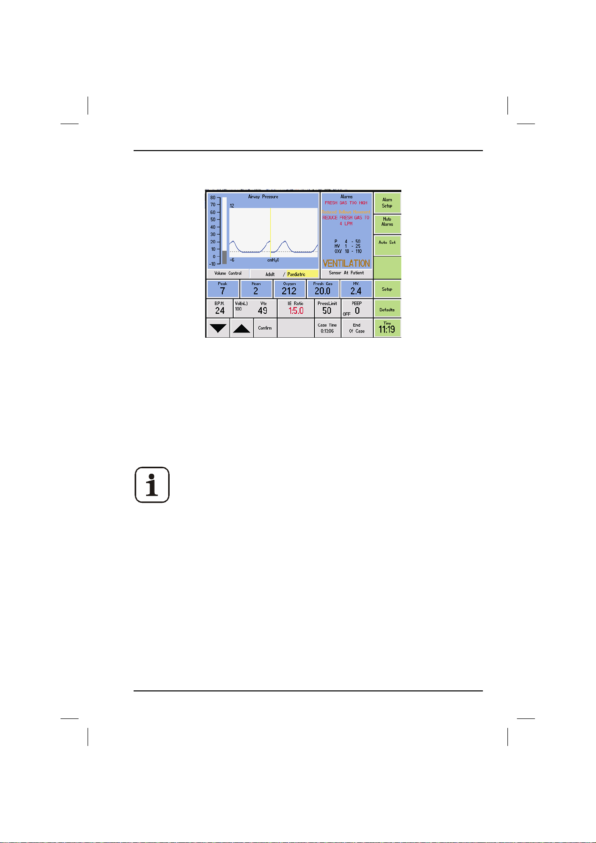
Section 2 - 700/900 Series Ventilators
Now rotate to It. It IMMEDIATELY shows the correct value, just CLICK and
accept.
If nothing happens during the first 12 seconds of the alarm the suggested I:E will
be forced. The alarm will continue to sound.
2. Operation
2.2.6 Oxygen Calibration
The Oxygen Calibration menu allows adjustment of the displayed oxygen
concentration to match the gas that the probe is exposed to; this is normally
100% pure oxygen.
NOTE: Calibration is only possible if the ventilator is in Standby
and a probe is connected.
1. Ensure O2 is selected as monitored parameter.
2. Press the Setup menu key, Oxygen Calibration.
3. Expose the probe to 100% pure oxygen flow or 21% room air.
4. Adjust the displayed value to 100% or 21% as applicable by turning and
pressing the Trak wheel.
5. Press the Trak wheel again to start the calibration process. This takes
approximately one minute and a countdown is displayed whilst it is in
progress.
6. Once the calibration process is complete return to the main screen, stop the
flow of pure oxygen and expose the probe to room air for a few minutes.
7. The oxygen concentration should nominally read 20.9+/-0.5%.
700/900 Series Ventilators User Manual 43
Page 46
2. Operation
Section 2 - 700/900 Series Ventilators
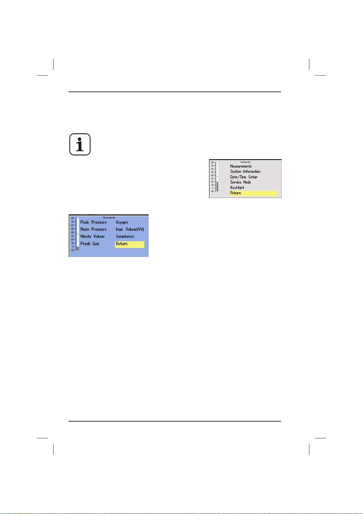
2.3 The Measurements Menu
The Measurements Selection menu allows the operator to assign parameters to
the second row of on-screen buttons.
The features available will depend on the operating mode.
1. Press Setup Menu.
2. Select Configuration Menu.
3. Select Measurements.
The Measurements Selection Menu opens.
3. Turn the Trak Wheel to highlight a feature on the menu, for example Fresh
Gas.
4. Press the Trak Wheel. The left-hand button on the second row of displayed
parameters is highlighted.
5. Turn the Trak Wheel to highlight each button in turn until a new one is
selected.
6. Press the Trak Wheel again to assign Fresh Gas to the highlighted button and
return to the Features Selection menu. Follow the same process to un-assign
a button.
7. Select Return to close Measurements Selection Menu.
8. Select Return to close the Main menu and go back to the normal screen.
44
700/900 Series Ventilators User Manual
Page 47
Section 2 - 700/900 Series Ventilators
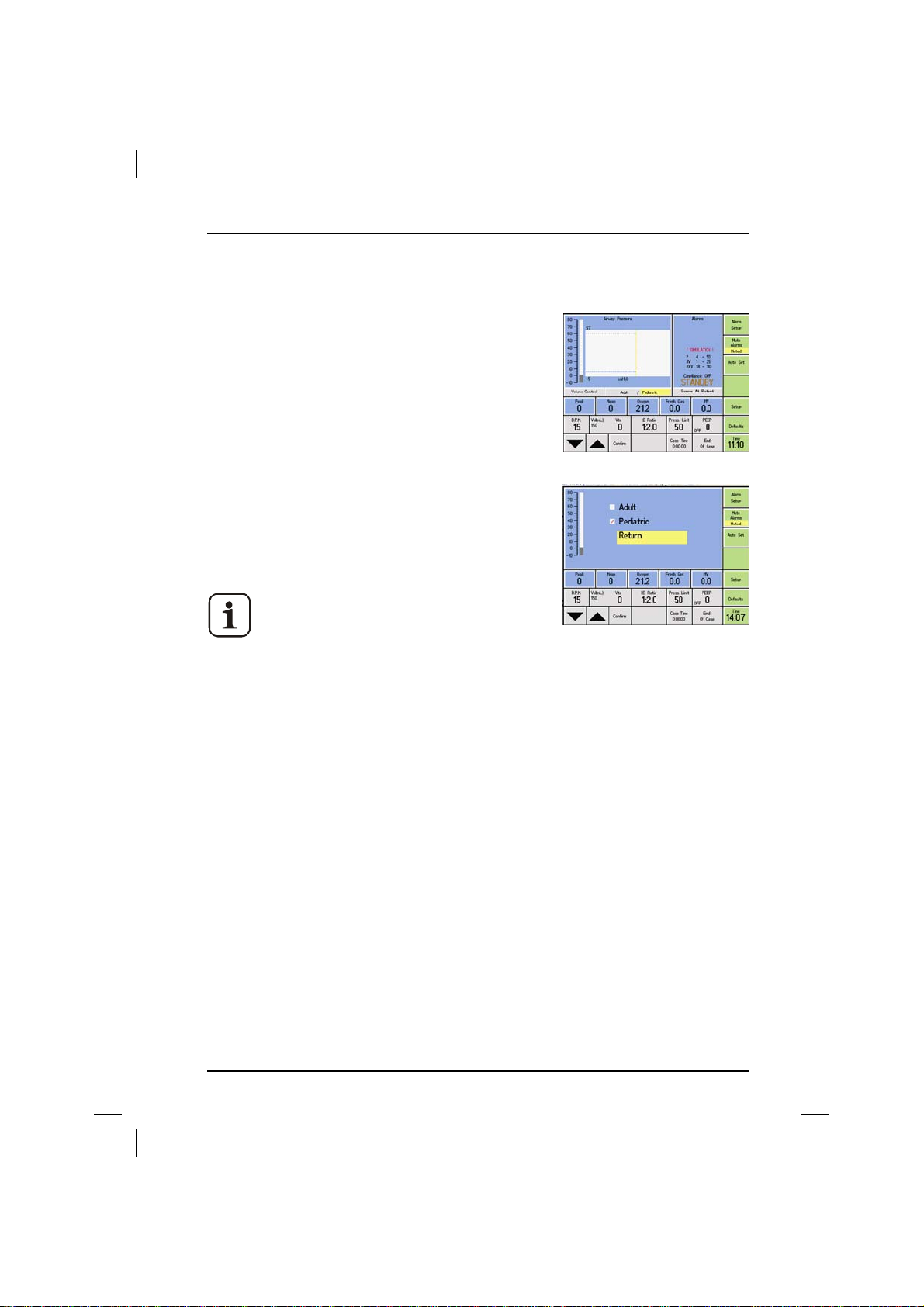
2.3.1 Adult and Pediatric
1. Place ventilator into BAG or Standby.
2. To select either Adult or Pediatric mode
press the Defaults Menu button.
3. Change selection and press return.
4. Or place into BAG or Standby mode and
press on the Adult/Pediatric button on the
main screen and change selection
5. Alternatively whilst in BAG or Standby mode
press the adult or pediatric button on the
screen, select and return.
Option can only be changed whilst
ventilator is in BAG or Standby mode and
not in run mode.
2. Operation
700/900 Series Ventilators User Manual 45
Page 48
2. Operation
Section 2 - 700/900 Series Ventilators
2.4 Sensor Placement
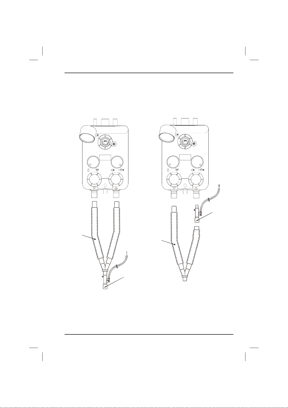
The sensor can be placed at two locations in the circuit at the patient, or at the
absorber expiratory port.
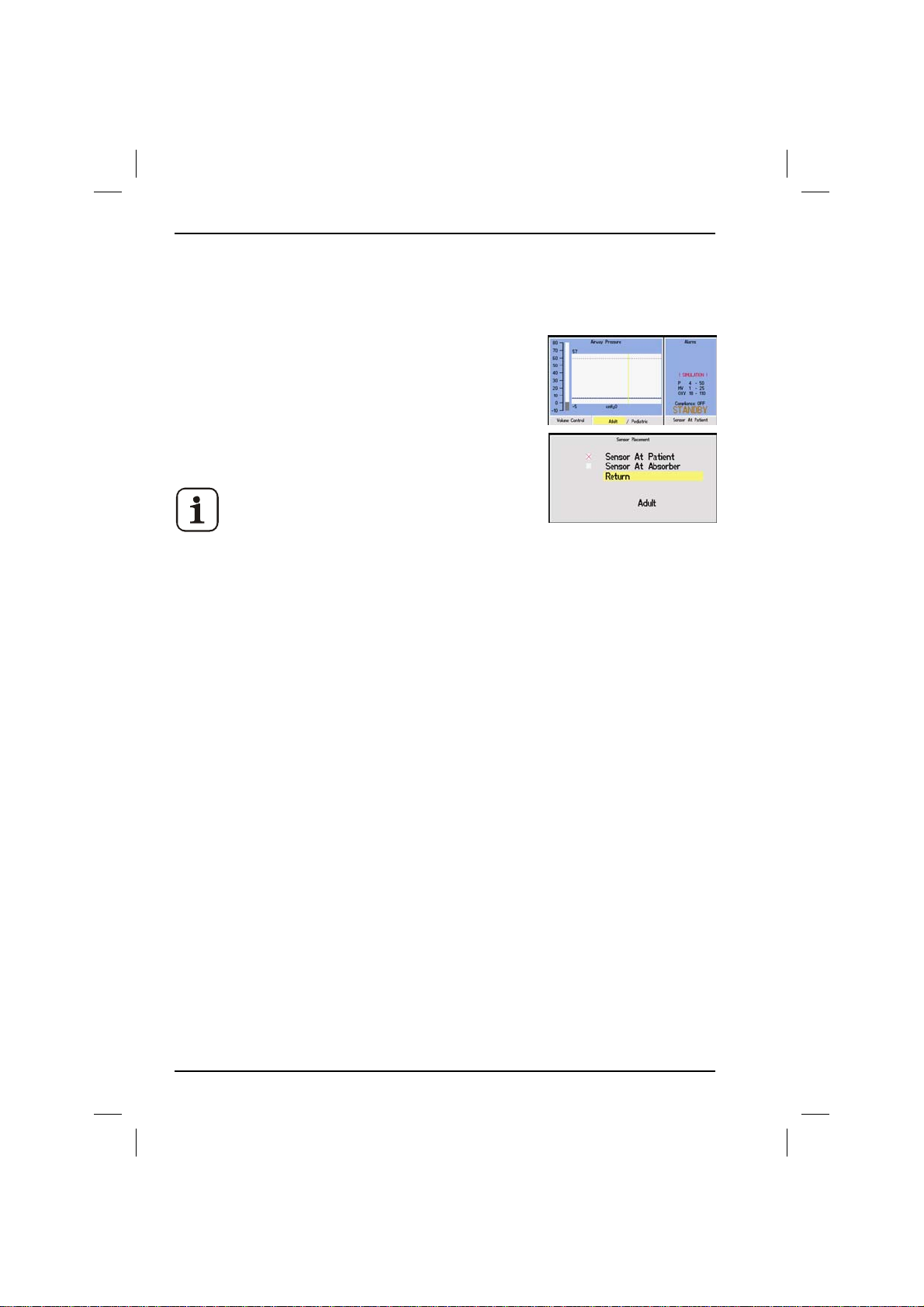
1. Place ventilator into Bag mode or Standby, to place
into Bag mode turn absorber switch to bag. To
place into standby place absorber in Bag mode then
press end of case on the screen and choose one of
the options to place ventilator into Standby mode.
2. Press Sensor button on screen.
This can only be done in standby mode and
not in run mode.
3. Select Absorber or Patient position using the Trak Wheel.
4. Select either “Sensor At Patient” or “Sensor At Absorber” and press the Trak
Wheel to confirm.
5. To come out of Standby, turn absorber switch to VENT.
When the sensor is at the absorber expiratory port the ventilator can only be run
in Volume Control and Pressure Control modes.
Placing the sensor at the absorber has several implications on the running of the
ventilator.
1. There is no inspired volume measurement box. If this was previously selected
as a feature when the sensor is chosen to be at absorber, the box is forced
off the screen. The “Inspired Volume” feature is grayed out and inaccessible.
2. The user cannot select to view spirometry graphs. Waveform Select is grayed
out and inaccessible in the menu. If the graph was previously set to “Flow/
Pressure” or “Flow/Volume” when “Sensor at Absorber” is chosen, the graph is
forced to be pressure.
3. If the sensor placement setting is different between adult and pediatric, a
warning banner is displayed when switching between adult and pediatric or
when the ventilator is first turned on. The banners are “Check Sensor Fitted At
Patient” and “Check Sensor Fitted at Absorber”. If adult and pediatric have
the same sensor placement, no banner is displayed.
If you start to run and then immediately go into the menus, this may occur
whilst in the menus. If it does the banner is displayed and you are forced
back to the run screen.
46
700/900 Series Ventilators User Manual
Page 49
Section 2 - 700/900 Series Ventilators
y
2. Operation
If the absorber position is changed and it is required that this change be
permanent the user must either save current settings or save hospital
defaults.
4. When switching to run from standby, a sensor position check is performed. If
the sensor is not in the position that has been set a banner is displayed
“check sensors position (either at patient or at absorber)”.
Y Circuit
Y Circuit
P
O2
%
Y Circuit
Y Circuit
Patient Airway
Patient Airwa
Flow Sensor
Flow Sensor
Connector
Connector
Spirometry
Spirometry
Sensor Head
Sensor Head
P
Patient Airway
Patient Airway
Flow Sensor
Flow Sensor
Connector
O2
%
Connector
Spirometry
Spirometry
Sensor Head
Sensor head
At Patient
At Absorber
Figure 4 Airway Sensor Placement with Blease Absorber with
Sensor at Patient and Sensor at Absorber
700/900 Series Ventilators User Manual 47
Page 50
2. Operation
Section 2 - 700/900 Series Ventilators
2.5 The Waveform Select Menu
From the Waveform Select option, the operator can choose to view one of two
Spirometry loops (Pressure/Volume or Flow/Volume) as an Airway Pressure
display and Airway flow display and Airway Flow waveform.
Select the desired display using the Trak Wheel.
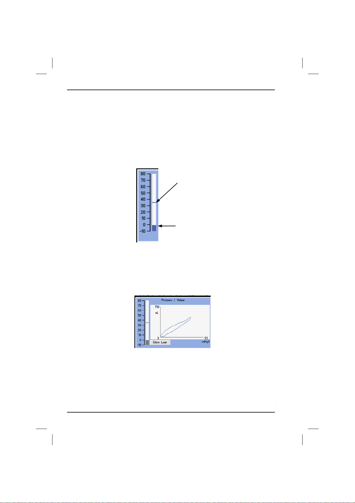
In all modes the airway pressure bar is shown to the left of the trace area. This
shows the real time airway pressure. The peak value of the last breath is also
displayed.
Previous Peak
Real Time Pressure Level
2.6 Spirometry
Once either of the spirometry waveforms has been selected from the waveform
menu, an extra box (’Store Loop’) becomes available on screen for selection.
48
700/900 Series Ventilators User Manual
Page 51
Section 2 - 700/900 Series Ventilators
2. Operation
Once the user is satisfied that the patient is in a stable pre-operative condition,
the next loop to be displayed can be saved.
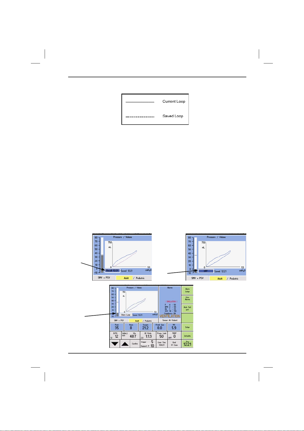
To save the loop, highlight the loop button directly below the loop and confirm.
A message that states saving, will be displayed. The next loop will be saved and
displayed in red. Up to 6 loops can be saved.
Any one of the stored loops can be recalled by highlighting the stored loop
button, then use the trakwheel up/down arrows to select the required loop, then
confirm.
By using the highlighted button, you can select which loop defined by time to
recall and display or turn the saved function off. As shown below.
2.6.1 Recalling loops
Recall a
Loop
(by saved
time)
Save a
Loop
(Time of
saving is
displayed
next to
button)
Turn
saved
Loop OFF
700/900 Series Ventilators User Manual 49
Page 52
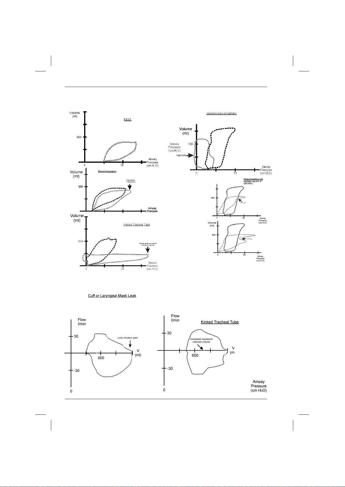
2. Operation
2.6.2 Pressure/Volume
Section 2 - 700/900 Series Ventilators
2.6.3 Flow/Volume
50
700/900 Series Ventilators User Manual
Page 53
Section 2 - 700/900 Series Ventilators
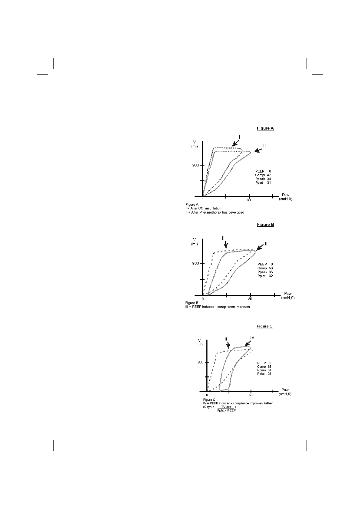
2. Operation
2.6.4 Pneumothorax during Laparoscopy - Diagnosis &
Treatment
Case Evolution
I. Intra-abdominal CO2 Insufflation
- Compliance drops
- Pplat increases
II. Pneumothorax Occurs
- Compliance drops further
- Pplat increases further
- ETC02 increases more sharply
* (The occurrence of pneumothorax
was confirmed through fluoroscopy)
III. Treatment with PEEP
- Compliance improves
- Pplat decreases gradually
- ETC02 decreases
IV. Deflation of the abdomen
700/900 Series Ventilators User Manual 51
Page 54
2. Operation
Section 2 - 700/900 Series Ventilators
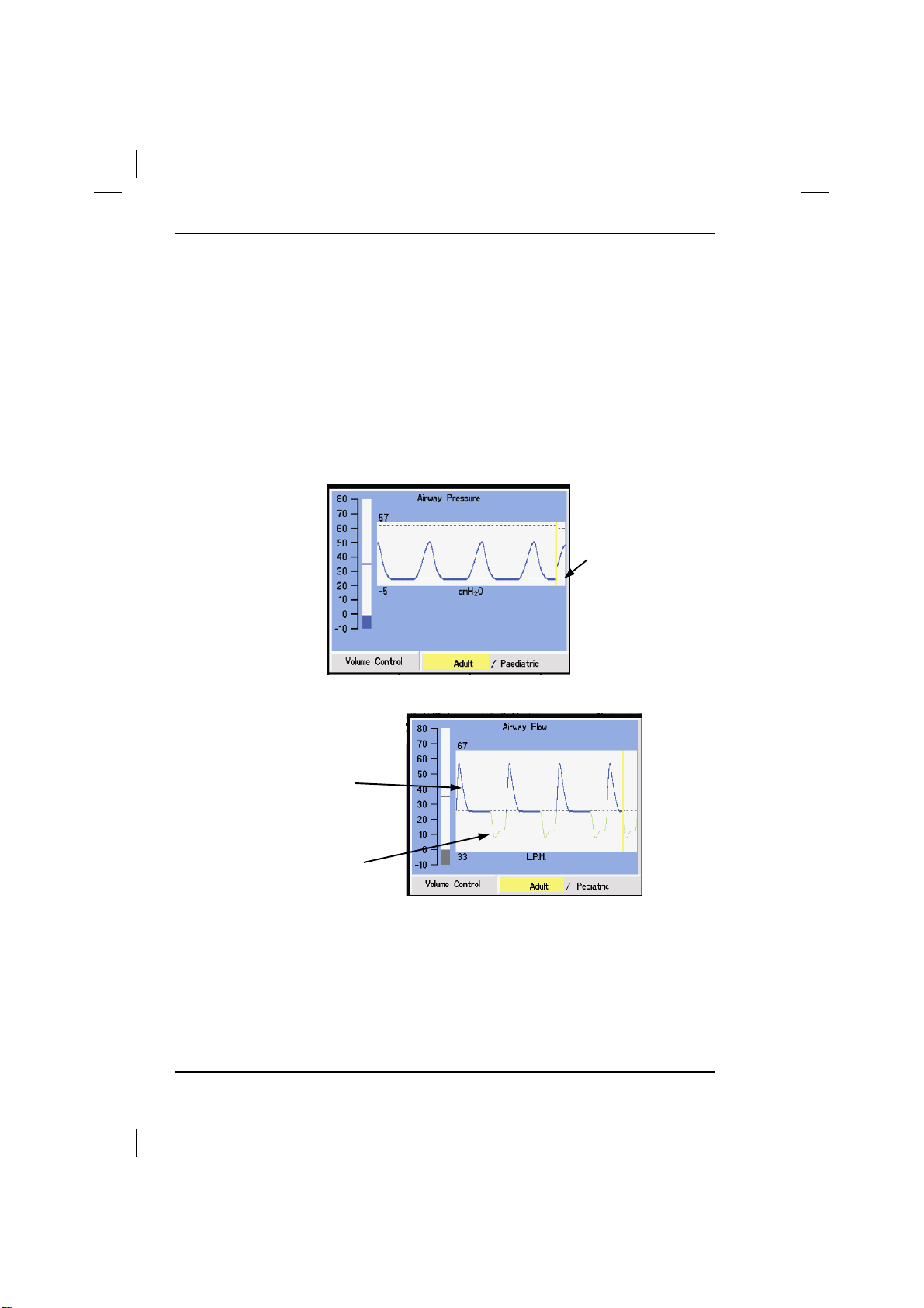
2.7 Airway Pressure
This waveform represents the airway pressure. The Trace autoscales so that the
amplitude is 80% of the available height. The high and low points are shown on
the left of the area bordering the trace. The zero graticule is shown as a black
dotted line.
When the pressure is greater than or equal to zero, the trace is blue and when it
is less than zero, it is shown in green.
Zero Graticule
2.7.1 Airway Flow
Expired from patient
Inspired to patient
This waveform represents the airway flow. The Trace autoscales so that the
amplitude is 80% of the available height. The scale to the side still shows airway
pressure. The zero graticule is shown as a black dotted line.
The flow to the patient is shown as green and the expired flow is shown as blue.
52
700/900 Series Ventilators User Manual
Page 55
Section 2 - 700/900 Series Ventilators
2. Operation
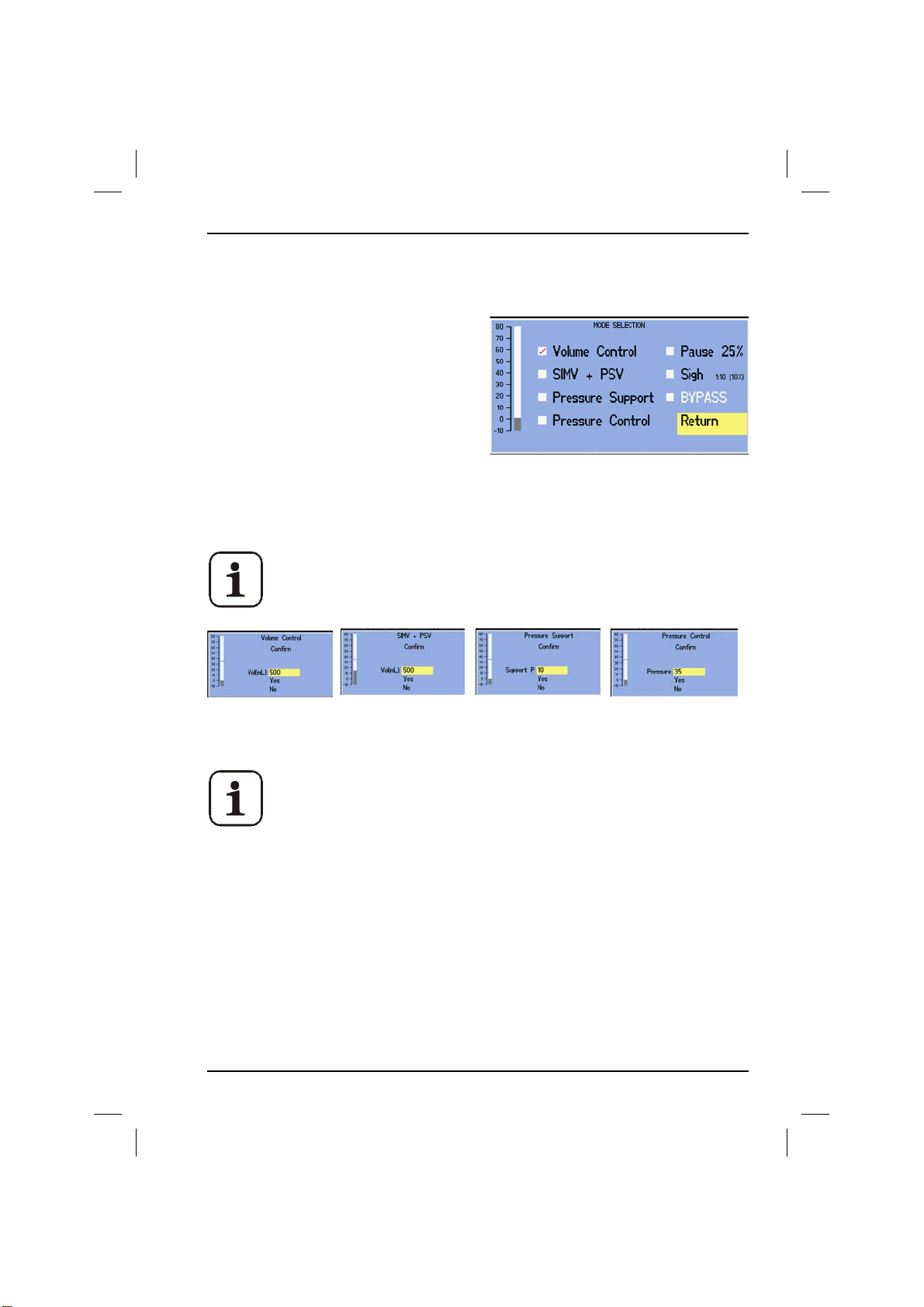
2.8 Mode Selection Menu
Refer to Section 1.6.3 for descriptions of the modes available.
1. Press Setup Menu.
2. Select Mode using the Trak wheel.
3. From the Mode selection menu,
(shown above) select the required new
mode using the Trak wheel.
A cross in the check box next to the
menu indicates that it is selected.
4. Each mode enables different options - the available functions are those which
are displayed in black text.
Before changing mode when the ventilator is in run mode, a prompt
screen will appear asking you to confirm or adjust the main
parameter for that mode. As shown below.
5. Alternatively, highlight mode on the main screen to select. Use arrows on
screen or trak wheel to change selection.
If the Trak wheel is not moved for approximately 30 seconds the
display will automatically return to the main screen.
Compliance Measurement is displayed only in Volume Control and
SIMV + PSV modes.
2.8.1 Cardiac Bypass
This selection represents the same standby function as End Case, except the case
timer does not stop and measurement of flow in the patient circuit does not
bring the ventilator back out of standby.
To exit Cardiac Bypass turn the ventilator ON by activating the bag to vent switch
or end the selection of Cardiac Bypass in the ventilator control menu.
700/900 Series Ventilators User Manual 53
Page 56

2. Operation
Section 2 - 700/900 Series Ventilators
2.8.2 Setting Parameters
1. From the normal Run screen, turn the Trak Wheel to the desired parameter
and press.
2. The selected parameter window is highlighted. Turn the Trak Wheel clockwise
to increase the set value or anti-clockwise to decrease the set value.
The value will not increase above the high pre-set limit, or decrease below the
low pre-set limit.
3. When the required value is displayed, press the Trak Wheel.
54
700/900 Series Ventilators User Manual
Page 57
Section 2 - 700/900 Series Ventilators
2. Operation
2.9 Alarms
The 700/900 series ventilator contains a number of pre-set and user-defined
alarms for patient monitoring and monitoring of the ventilator itself.
WARNING: An audible alarm indicates an anomalous condition
that may result in damage to the equipment or injury to the
patient. The cause of each alarm should be investigated and any
necessary measures taken to remove the alarm condition.
WARNING: The pressure high and pressure low alarms are
important for patient care.
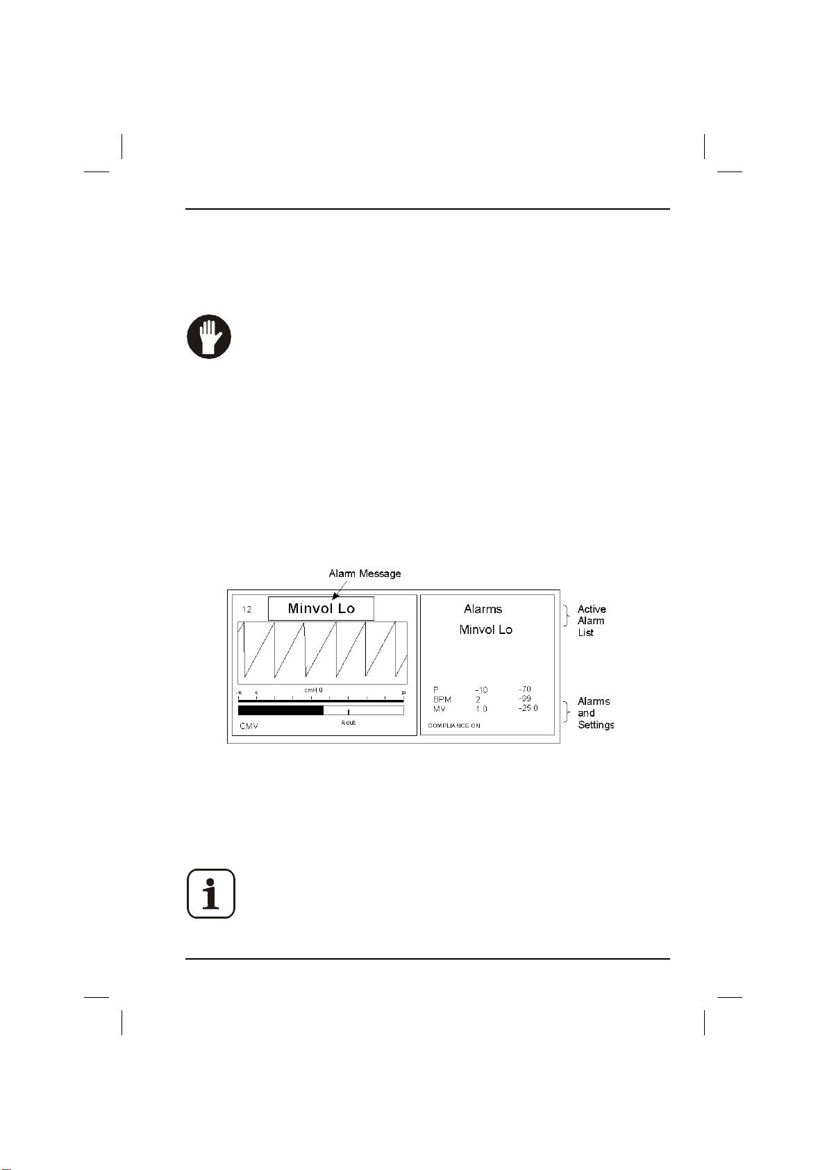
When an alarm is activated:
• an audible warning sounds;
• a flashing message appears in the activity zone of the display;
• the alarm is added to the list of active alarms in the alarm zone on the
screen.
The active alarm is displayed on the list in the alarm zone for a minimum Of
30 seconds. If the alarm condition is removed during this time, the alarm is
automatically cleared from the list. If more than one alarm is activated, each new
alarm is added to the top of the list.
Check alarms periodically at clinically suitable intervals. If the
audible alarm or visual indicator of any alarm function fails to
activate during any alarm condition, or fails to reset after the
alarm has been cleared, refer the unit to an authorized
technical engineer.
700/900 Series Ventilators User Manual 55
Page 58

2. Operation
Section 2 - 700/900 Series Ventilators
2.9.1 Alarms Summary
The available alarms are summarized in the table below. Each alarm is described
in detail later in this section.
ALARM RANGE/SETTING
Apnea (Default) 30 seconds User Defined 15-60 secs.
Low Supply Gas Pressure Pre-set. 35 ±0.5 psig.
Vent Inoperative Pre-set. System Failed.
Setting Error Pre-set. Ventilatory parameter set out of range.
Sustained Pressure Pre-set. less than 5 cm H2O (adult) or 3 cm H2O in
(paediatric) change in pressure per breath.
Power Fail Pre-set. Mains electrical supply failure
Battery Low Pre-set. <15 minutes battery life remaining.
No Charge Pre-set. Mains supply ON, battery not charging.
Comms fail Pre-set. Internal communications error.
Pressure High User defined. 5 cm H2O to 70 cm H2O.
Pressure Low User defined. 4 cm H2O to 50 cm H2O.
MV High User defined. 2 l/m to 25 l/m adult. 1 I/m to 25 I/m ped.
MV Low User defined. 1 l/m to 24 l/m adult. 0 I/m to 24 I/m ped.
High BPM User defined. 1 BPM to 99 BPM.
Low BPM User defined. 0 BPM to 98 BPM.
High Oxygen User defined. 19% to 110%.
Low Oxygen User defined. 18% to 109%.
PEEP Error Pre-set.
Under Pressure Pre-set.
Fresh Gas too High Pre-set
56
700/900 Series Ventilators User Manual
Page 59

Section 2 - 700/900 Series Ventilators
2. Operation
2.9.2 Pre-set Alarms
2.9.3 Apnea Alarm
Once an initial breath has been detected, the alarm is activated if the ventilator
ceases to record a tidal volume for the set apnea time.. This is the case when the
system is selected to either BAG or VENT.
2.9.4 Low Supply Gas Pressure Alarm
Activates when the pressure of the gas supply falls below that required for correct
ventilator operation.
As a safety precaution while this alarm is active, the ventilator flow delivery
system is prevented from trying to compensate for the lack of supply gas by
opening the flow control valves further. This stops the large surge of flow that
may otherwise occur if the supply gas is suddenly re-applied, particularly when a
bottled supply is changed.
WARNING: If the supply gas pressure is reduced, the patient
minute volume may be reduced and injury to the patient could
result. Do not use the ventilator if the supply pressure cannot be
maintained.
2.9.5 Vent Inoperative Alarm
Activates if an internal fault is detected.
WARNING: The Vent Inoperative alarm indicates that the
ventilator cannot provide ventilation functions. Under no
circumstances should the ventilator be used on a patient while
this alarm is activated.
700/900 Series Ventilators User Manual 57
Page 60

2. Operation
Section 2 - 700/900 Series Ventilators
2.9.6 Setting Error Alarm
The setting error alarm is activated under the following conditions where the
ventilator’s performance limits are exceeded:
• The ventilator settings (BPM, I:E, TV) require a flow greater than 100 Ipm or
less than 1.5 Ipm.
• Mode switch setting is indeterminate.
• The internal feedback systems cannot accurately provide what is set.
• On occasions when extreme control settings are used, a difficult
combination of patient compliance and resistance may cause the ventilator
to exceed its specification as the feedback systems attempt to compensate,
but do not quite reach what is set.
2.9.7 Sustained Pressure Alarm
Activated if the patient breathing system pressure does not go through a pre-set
absolute pressure change as a breath is delivered. Two failed breaths activate the
alarm; two good breaths clear it. The pressure changes must be in a positive and
negative direction for each breath, and therefore the alarm will be activated if
there is a build-up of pressure.
Less than 5 cm H
breath.
58
O (adult) or 3 cm H2O (pediatric) change in pressure per
2
700/900 Series Ventilators User Manual
Page 61

Section 2 - 700/900 Series Ventilators
2. Operation
2.9.8 Power Fail and Battery Low Alarms
These alarms are indicated by a change in color of the LED adjacent
to the display. Under normal conditions the LED will be GREEN.
A few seconds after mains failure occurs, the Power Fail indicator is illuminated. If
the condition persists for more than one minute, the alarm is activated and the
LED remains illuminated RED.
To conserve power, the display is switched off while the Power Fail alarm is
activated. To restore power to display press a key or turn trak wheel.
The ventilator continues to function normally, powered by its internal battery for
a minimum of 1 hour.
When the internal battery is nearly exhausted and has less than 15 minutes of
running capacity left, the Battery Low alarm is activated and the Battery Low
indicator is illuminated AMBER.
This is an estimated time and should not be relied on.
When mains power is restored, the Battery Low indicator may remain lit for a few
minutes as the battery recharges.
If the Battery Low indicator illuminates without a mains failure, there may be a
battery or charging fault. The ventilator will then have no battery backup and
must not be used until the fault has been repaired.
2.9.9 No Charge
Mains supply ON, battery not charging.
2.9.10 Comms Fail
Internal communications error between control and monitoring systems.
2.9.11 PEEP Alarm
Activated if the measured PEEP is more than 25% above the set value, or above
5cm H2O if PEEP is not set.
2.9.12 Under Pressure Alarm (PCV mode only)
Activated when the peak pressure is less than 80% of the set pressure and greater
than the lower pressure limit.
700/900 Series Ventilators User Manual 59
Page 62

2. Operation
Section 2 - 700/900 Series Ventilators
2.10 User Defined Alarms
2.10.1 Pressure High Alarm
In pressure control mode the high pressure alarm is 25% above set pressure. In
Volume Control mode, SIMV and Pressure Support modes the pressure high
alarm limit is set via pressure limit setting on main screen. It will be activated if
one of the following occurs:
• The patient breathing system pressure rises significantly above that set
limit.
• The patient breathing system pressure has not fallen after a pressure-
terminated breath has cycled into expiration.
• Pressure cycling occurs in adult ventilation mode.
Due to the connection with the pressure limit control, it is
possible with some patients that the alarm may occasionally be
activated when pressure limiting at low pressures in pediatric
mode.
The alarm is automatically cleared when the pressure falls.
2.10.2 Pressure Low Alarm
The alarm is automatically cleared on the second breath that exceeds the alarm
limit, if within 20 seconds. The pressure low alarm is activated if the pressure falls
below the set PEEP + 4cmH2O for more than 20 secs.
2.10.3 MV High Alarm
Range 2 Ipm to 25 Ipm adult mode.
Range 1 lpm to 25 lpm ped mode.
Activated when the monitored expired volume exceeds the set limit. When the
expired volume falls below the alarm limit, the alarm immediately clears.
2.10.4 MV Low Alarm
Range 0 Ipm to 24 adult mode.
Range 0 lpm to 24 lpm ped mode.
Activated when the monitored expired volume falls below the set limit.
60
700/900 Series Ventilators User Manual
Page 63

Section 2 - 700/900 Series Ventilators
2.10.5 High BPM Alarm
Range 1 BPM to 99 BPM
Activated when the monitored BPM exceeds the set level.
2.10.6 Low BPM Alarm
Range 0 BPM to 98 BPM
Activated when the monitored BPM falls below the set level.
2.10.7 High Oxygen Alarm
Range 19 % to 110 %
Activated when the monitored oxygen level rises above the set level.
2.10.8 Low Oxygen Alarm
Range 18 % to 109 %
Activated when the monitored oxygen level falls below the set level.
2. Operation
2.10.9 Fresh Gas Too High
Activated in two ways:
1) during compliance compensation if fresh gas goes above basal flow.
2) during Ventilation if fresh gas is more than 65% of required tidal volume.
700/900 Series Ventilators User Manual 61
Page 64
2. Operation
Section 2 - 700/900 Series Ventilators
2.11 Auto Alarms
The user can choose to automatically set the alarm parameters at any time while
the ventilator is running.
This is done by highlighting the AUTO SET once off is displayed.
AUTO SET
The ventilator requires parameters to stabilize, before the alarms can
be set.
The set values are
the following cases:-
• pressure where the minimum value is always 4 cm H
• oxygen where minimum value is 18%.
± 25% of the current monitored value. Except in
O.
2
AUTO SET
OFF
AUTO SET
SET
If the user changes any of the user selectable parameters or
changes mode the set alarms will be cancelled and returned
to the values set previous to turning them on. When this
occurs the ventilator will beep and a message displayed on
screen.
If the user goes into the Set Alarms Menu whilst the auto
alarms are set the previous values set will be restored
without warning
.
The user can restore the previous set of alarm limits at any
time by either selecting Off in the auto box, or going into the
Alarm Limits Menu and making no changes.
62
700/900 Series Ventilators User Manual
Page 65
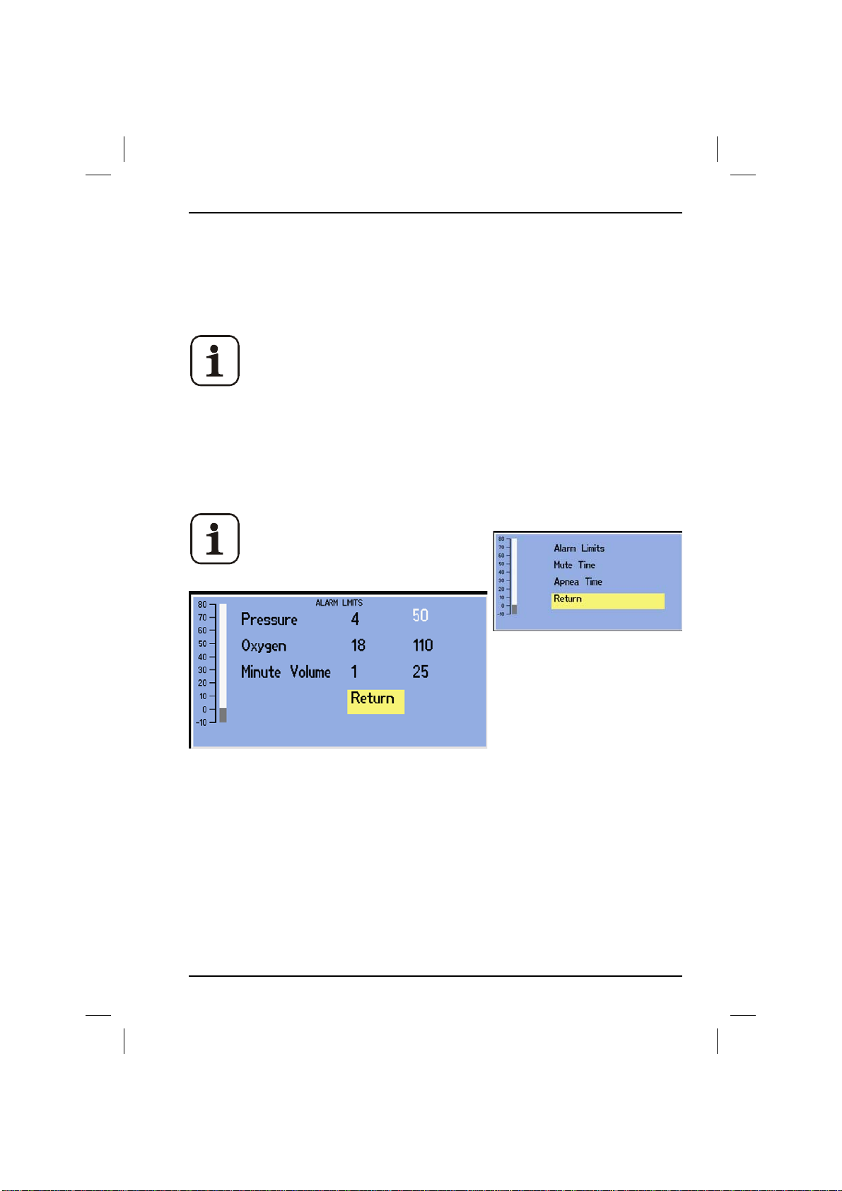
Section 2 - 700/900 Series Ventilators
2. Operation
2.12 The Alarms Setup Menu
2.12.1 Setting Alarms
From the Alarms Setup Menu, high and low alarms appropriate to the mode of
operation and the particular patient can be set.
High and low alarms are linked intelligently so that a low alarm
value greater than a high alarm value cannot be set.
1. Press Alarm Setup Menu.
2. Select Alarm Limits
3. Turn the Trak Wheel to highlight and select the desired alarm, then press the
Trak Wheel.
Only those alarms that are relevant to the current operating
mode are displayed.
4. Alarm levels can be set by turning the Trak Wheel clockwise (increase) or
anti-clockwise (decrease).
5. When the required value is displayed, press the Trak Wheel to set the
parameter.
6. Select Return to close the screen and return to the alarm options.
700/900 Series Ventilators User Manual 63
Page 66
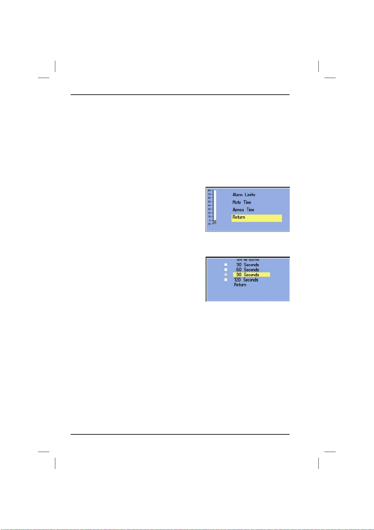
2. Operation
Section 2 - 700/900 Series Ventilators
2.12.2 Alarm Mute
Alarms can be muted for a pre-set time, up to a maximum of 2 minutes, by
pressing Mute.
2.12.2.1 Setting the Alarm Mute
Time
1. Press Alarm Menu.
2. The alarm menu opens. Select Mute Time.
The Mute Time Selection menu opens.
3. Select the required mute time in the range
shown.
A cross in the check box next to a menu item
indicates that it is selected.
4. Select Return to close the menu.
64
700/900 Series Ventilators User Manual
Page 67
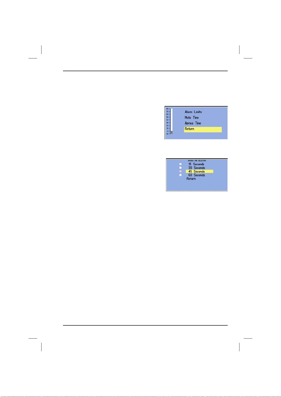
Section 2 - 700/900 Series Ventilators
2.12.3 Setting the Apnea Time
1. Press Alarm Setup Menu.
2. The Alarm Setup Menu opens. Select Apnea
Time.
The Apnea Time Selection menu opens.
4. Select the required Apnea time in the
range shown using the Trak wheel.
A cross in the check box next to a menu
item indicates that it is selected.
5. Select Return to close the menu.
2. Operation
700/900 Series Ventilators User Manual 65
Page 68
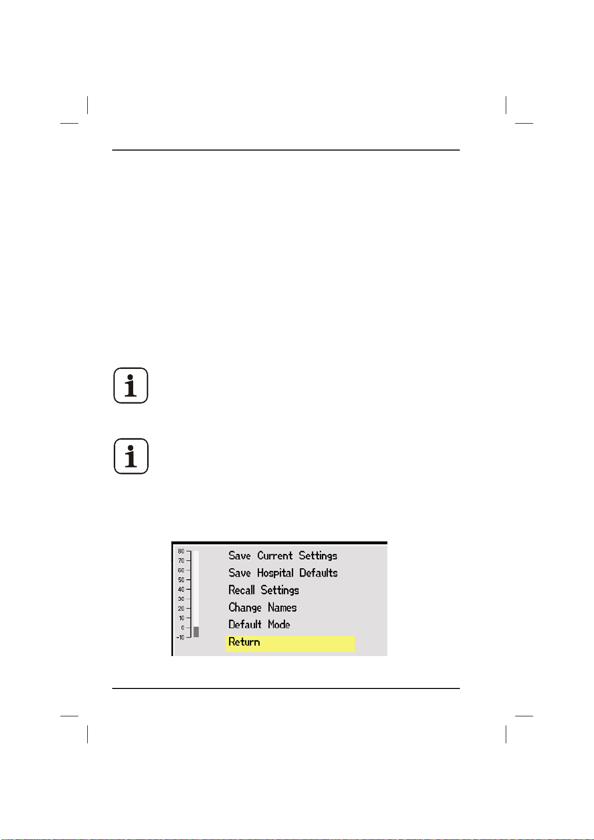
2. Operation
Section 2 - 700/900 Series Ventilators
2.13 The Defaults Menu
From the Defaults menu it is possible to:
• save the current settings so that they can be re-used later;
• set hospital defaults;
• select previously stored settings
• change setting names;
• change the basic setup of the ventilator;
The first three items can be stored in Adult or Pediatric mode. Ensure
that the Patient Selection Switch is in the required position before
selecting these items.
Note: Certain options are password protected. Contact the
distributor for further information.
2.13.1 Change Names
A user name must be set before any settings can be saved.
1. Press Defaults Menu. The Defaults Menu opens.
66
700/900 Series Ventilators User Manual
Page 69
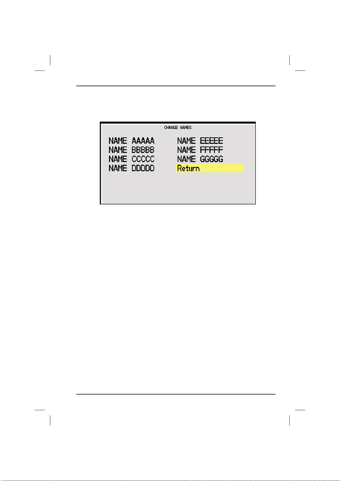
Section 2 - 700/900 Series Ventilators
2. Select Change Names. The Change Names menu opens.
3. Select one of the names displayed using the Trak Wheel. The first character of
the name is displayed in Red when the Track wheel is pressed.
4. Turn the Trak Wheel clockwise to move through the alphabet from A to Z
and then through the numbers 1 to 0. To insert a space, use the under-score
character ( _ ).
2. Operation
5. Press the Trak Wheel when the desired character is displayed to enter the
character and move the cursor on to the next letter.
6. Repeat steps 3 and 4 until the name is complete. A total of 10 characters
must be entered - even if there are spaces. Pressing the Trak wheel at the 10th
character will cause the name to be saved.
7. Press Default Menu again to save the name and exit the menu.
700/900 Series Ventilators User Manual 67
Page 70
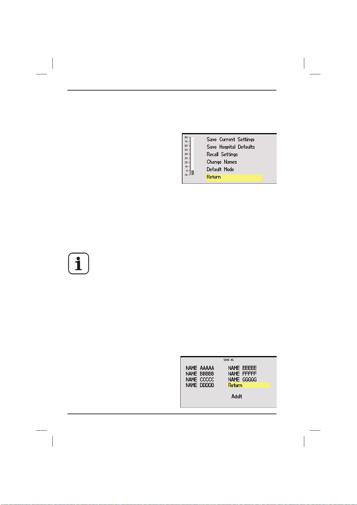
2. Operation
Section 2 - 700/900 Series Ventilators
2.13.2 Save Hospital Defaults
This menu option allows the change of default start up settings from the factory
set ones and is password protected. Contact the distributor for further details.
1. Press Defaults Menu. The Default Menu
opens.
2. Select 'Save Hospital Defaults'.
3. Enter the password one letter at a time
using the Trak Wheel.
4. Press the Trak Wheel to store the ventilator's current settings as the start up
settings.
2.13.3 Saving and Recalling Settings
The configuration of the ventilator can be saved and recalled. This includes all
user-settable features, alarm limits etc.
Two totally different sets of parameters can be set up - one for
Adult and one for Pediatric.
2.13.4 Save Current Settings
1. Press Default Menu.
2. The Default Menu opens. Using the Trak Wheel, select Save Current
Settings?
3. The Save As menu opens. Select a name from the menu.
4. Press the Trak Wheel to initiate the save. A message will be displayed played
stating the setting (Adult or Ped), and the saved name.
5. Select Return to close the Save As
menu.
68
700/900 Series Ventilators User Manual
Page 71

Section 2 - 700/900 Series Ventilators
2. Operation
2.13.5 Recall Previous Settings
1. Press Default Menu.
2. The Default Menu opens. Using the Trak Wheel, select Recall Settings?
3. The Recall Settings menu opens. Select a name from the menu using the Trak
Wheel
4. Press the Trak Wheel to initiate recalling parameters. A message will be
displayed stating the mode (Adult or Ped), and the recalled name.
5. Select Return to close the Save As menu.
700/900 Series Ventilators User Manual 69
Page 72
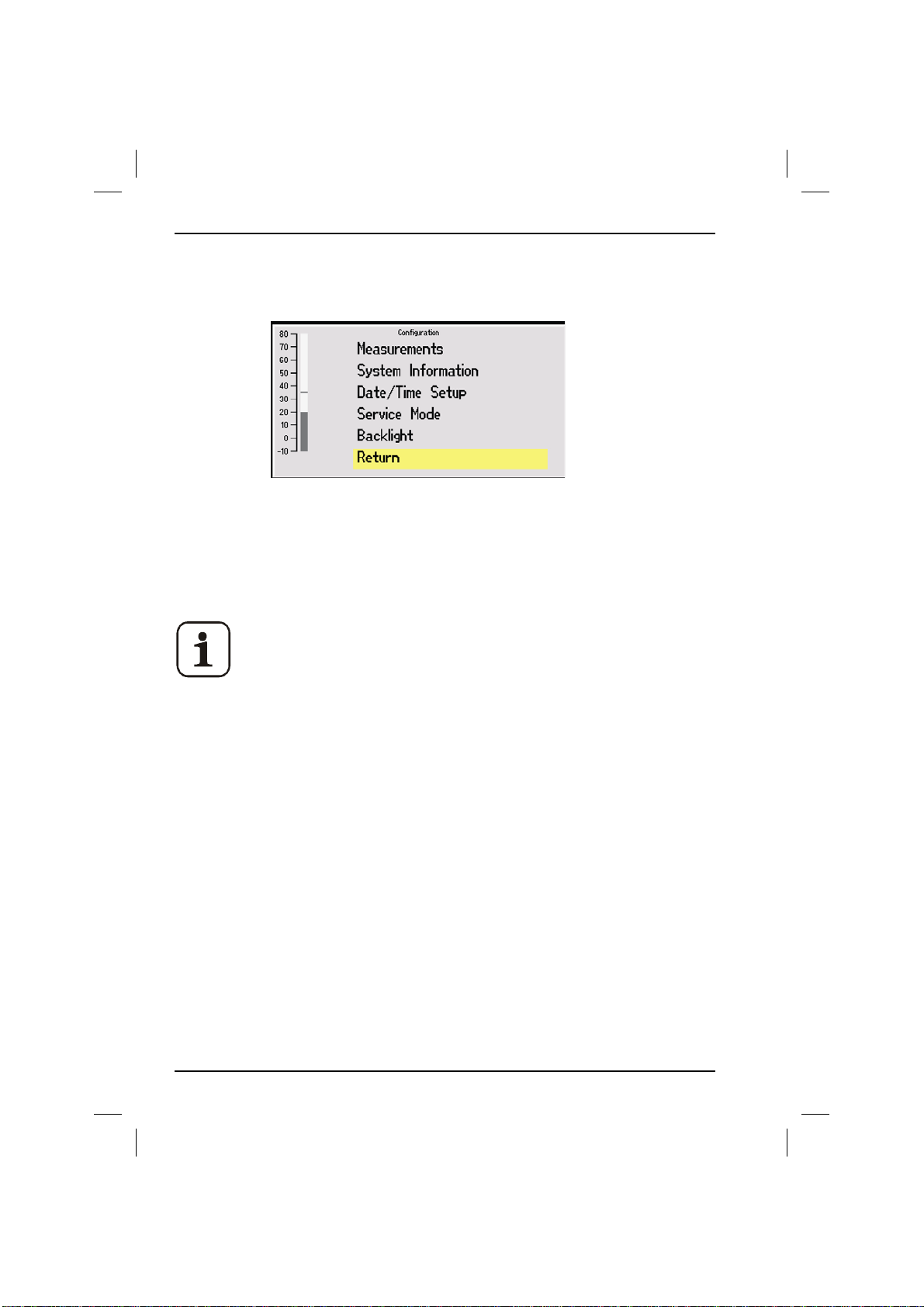
2. Operation
Section 2 - 700/900 Series Ventilators
2.13.6 Configuration
By selecting the Configuration option, the following menu is displayed:
2.13.7 Set Up
The Set up menu allows the user to:
• calibrate the fresh gas sensor
• enable absorber switching
Please Note: These options are password protected. Contact the
supplier for further information.
1. Press Setup Menu.
2. Select configuration.
3. Select Service Mode.
4. Enter the password supplied by the distributor.
70
700/900 Series Ventilators User Manual
Page 73

Section 2 - 700/900 Series Ventilators
2. Operation
2.13.8 Fresh Gas Calibration
The CGO of the trolley must be open to atmosphere for the
calibration to be accurate.
1. Put the ventilator into Standby.
2. Enter the Setup Menu and choose Configuration and then Service Mode.
In order to continue, the password will need to be obtained
from Blease. This is a multi point calibration.
3. Disconnect the gas supply and turn off cylinders to ensure that there is no gas
flow when zero is set. Having set zero reconnect the gas supply and turn on
the cylinders, you will be prompted for each required flow, after each flow has
been set there will be an audible beep to confirm.
The calibration can be aborted at any time - doing so will cause the last set of
saved calibration values to be used. If the user inadvertently sets the same
flow for two readings, the calibration will automatically be aborted.
2.13.9 Sigh Setting
1. Enter the Setup Menu and choose Configuration and then Service Mode.
In order to continue, the password will need to be obtained from
Blease.
2. Select Sigh setting.
3. The volume of the sigh breath can be set to the volume plus 5% - 60% of the
set volume in increments of 5%. (Default settings are 1-10 and 10%).
4. The frequency can be set to between 1 in 10 breaths to 1 in 100 breaths.
2.13.10 Absorber Setting
1. Having pressed the Setup button and chosen Configuration, select Absorber
Setting from the menu.
2. If Bag/Vent switch detection is provided, select Absorber Fitted from the
options otherwise, leave it unchecked.
2.13.11 System Information
This menu shows important details regarding the ventilator for reference
purposes.
700/900 Series Ventilators User Manual 71
Page 74

Notes
72
700/900 Series Ventilators User Manual
Page 75

Section 3 - 700/900 Series Ventilators
3. Installation
3.1 Cautions
An explosion hazard could occur if this equipment is used with
flammable anesthetic agents such as ether or cyclopropane. To avoid
the risk of explosion, use this equipment only with anesthetic agents
that comply with the requirements on non-flammable anesthetic
agents in the IEC standard 'Particular Requirements for the Safety of
Anesthetic Machines'.
Use of a driving gas other than oxygen or air may damage the
ventilator and will cause inaccurate operation, resulting in potential
injury to the patient. Do not use any other driving gas.
The performance of this equipment may be adversely affected by
extremes of temperature. The equipment should not be used if the
ambient temperature is below 10oC (50oF) or above 40oC (104oF).
The use of antistatic or electrically conductive breathing tubes and
high frequency electric surgery equipment may cause burns and is
therefore not recommended in any application of this machine. The
ventilator is not suitable for use with flammable anesthetic agents
such as ether and cyclopropane and therefore the use of antistatic
breathing tubes and face masks is in any case unnecessary.
3. Installation
This equipment may be damaged if the gas supply pressure is too
high. The ventilator must only be connected to gas pipeline supply
lines that are fitted with pressure relief valves that limit the supply
pressure to less than 7 bar.
The ventilator may be adversely affected by the operation of
equipment such as high frequency surgical (diathermy) equipment,
defibrillators or short-wave therapy equipment in the vicinity.
700/900 Series Ventilators User Manual 73
Page 76

3. Installation
Cautions Cont.
To preserve battery life, never store the ventilator with its battery
discharged. Do not store or use the ventilator in close proximity to
heat sources of any kind.
In the event of a mains electrical power failure when the ventilator is
running from its internal battery, do not remove the mains plug from
the mains supply as this would prevent the immediate resumption of
normal operation when the mains power is restored.
Excessive electronic noise caused by poorly regulated devices may
interfere with the proper functioning of the ventilator. To avoid this,
do not connect the ventilator to the same mains supply outlet as
electrically noisy equipment such as electrocautery units. Do not use a
mains extension lead to connect the ventilator to the mains electrical
supply.
The driving gas is discharged through the port on the rear panel of the
ventilator. This port must be completely free of any obstruction and
should have nothing connected to it. The exhaust gas is oxygen or air
and does not contaminate the environment.
A negative or positive pressure applied to the EXHAUST port of the
bellows assembly results in positive pressure in the patient breathing
system. The scavenging system must therefore not generate more
than 5 cm H2O positive or negative pressure when connected to the
ventilator. The use of an AGSS to EN 740 1999 is recommended. Do
not connect a PEEP valve to the EXHAUST port of the bellows base.
This will increase the pressure inside the bellows and cause it to
detach from the base, resulting in a serious malfunction. Any problem
arising from an improperly functioning scavenging system is solely the
responsibility of the user.
Section 3 - 700/900 Series Ventilators
74
700/900 Series Ventilators User Manual
Page 77

Section 3 - 700/900 Series Ventilators
Notes
3. Installation
700/900 Series Ventilators User Manual 75
Page 78

3. Installation
Section 3 - 700/900 Series Ventilators
Notes
76
700/900 Series Ventilators User Manual
Page 79

Section 3 - 700/900 Series Ventilators
3. Installation
3.2 Pre-Use Checks
Prior to connecting the ventilator to a patient, the unit must be
run to verify that it is functioning correctly. Before using the
ventilator, check that all connections are correct and that there
are no leaks.
1. Switch on the mains power supply.
2. Check that the audible alarm sounds at switch on.
3. Select and carry out the procedure for pre-use tests.
This will perform the compliance test and leak test the system.
4. Follow the on screen instructions.
700/900 Series Ventilators User Manual 77
Page 80

3. Installation
Other alarms may also be activated ie. the sustained pressure.
CAUTION: Injury to the patient may result if a faulty ventilator is
used. If there is any malfunction, do not use the ventilator. Refer
to Troubleshooting for help. If the malfunction cannot be
rectified, call an authorized technical engineer or return the
ventilator to the supplier.
CAUTION: If an alarm condition is ignored, injury to the patient
may result. Always check the alarms before connecting the
ventilator to a patient. If the audible alarm or the visual
indicator of any alarm function fails to activate during an alarm
condition, or fails to reset after the alarm has been cleared, the
ventilator must not be used. Contact an authorized technical
engineer.
Section 3 - 700/900 Series Ventilators
78
700/900 Series Ventilators User Manual
Page 81

Section 3 - 700/900 Series Ventilators
3. Installation
3.3 Discharged Battery
If the internal battery is fully discharged, the power failure alarm will not function.
Charging the battery for 2 hours from a discharged state will allow a minimum of
2 minutes of continuous audible alarm. The audible alarm should be verified
before returning the unit to service.
A fully charged battery (8 hours) in serviceable condition will allow the ventilator
to run for a minimum of one hour.
CAUTION: To preserve battery life, never store the ventilator with
its battery discharged. Do not store or use the ventilator in close
proximity to heat sources of any kind.
700/900 Series Ventilators User Manual 79
Page 82
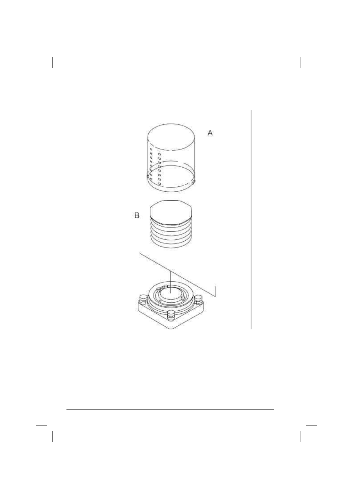
3. Installation
Section 3 - 700/900 Series Ventilators
3.4 Exchanging Bellows Units
Figure 5 Exchanging Bellows Units
A Adult Bellows Cover
B Adult Bellows
80
700/900 Series Ventilators User Manual
Page 83

Section 3 - 700/900 Series Ventilators
3. Installation
3.4.1 Installing the Adult Bellows
1. Remove the bellows housing by twisting it slightly anti-clockwise until the
bayonet tabs are free, then lift it from the base.
2. Mount the adult bellows.
3. Push the adult bellows housing down over the bellows, then twist it slightly
clockwise to engage the bayonet tabs.
WARNING: At pressures above 10 cm H2O differential positive
pressure, the bellows may be dislodged from the mounting ring,
resulting in a dangerous malfunction of the ventilator. Do not
exceed the stated pressure.
700/900 Series Ventilators User Manual 81
Page 84
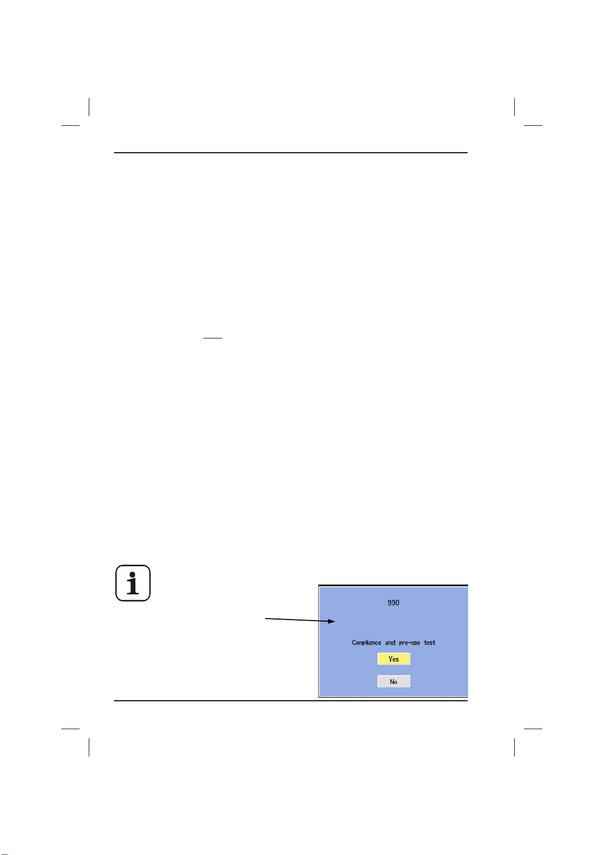
3. Installation
Section 3 - 700/900 Series Ventilators
3.5 Pre-use Test
3.5.1 Fresh Gas
Fresh gas (FG) flow adds to the delivered Tidal Volume (TV) during the inspiratory
period. To compensate, the delivered volume must be reduced.
The formula for this reduction is:
Effective TV = TV - (( FG Flow Rate/60) x Insp Time (sec))
For example:
Let FG flow = 5 LPM, TV = 600 ml, frequency = 10 BPM, I:E = 1:2.0
60
5000 x 2 seconds = 166 ml
The new effective TV is:
600 - 166 = 434 ml
3.5.2 Compliance
Compression of gas in the dead space within the breathing system reduces the
tidal volume delivered to the patient. In an ideal ventilator, the Set TV would be
the volume of gas that is delivered to the patient's lungs. This cannot be achieved
because the anatomy of the patient is unknown. However, the Set TV can be
accurately delivered from the catheter mount, thus reducing Set TV errors to a
minimum.
To calculate the effect of breathing system compliance on the delivered TV it is
necessary to measure the capacity or compliance (C
be done as part of a pre-use check procedure.
1. Switch the unit ON. The compliance menu will be displayed.
The patient airway flow sensor head must be in the patient
circuit in order to carry out
compliance compensation.
2. You will be offered this screen.
) of the system. This can only
s
3. Select Yes to Compliance Compensation
and follow the instructions on screen.
82
700/900 Series Ventilators User Manual
Page 85

Section 3 - 700/900 Series Ventilators
3. Installation
The ventilator delivers a breath of known volume to the breathing circuit,
records the pressure (cm H2O) achieved and verifies that a leak is not
present.
3. The dead space is calculated as follows:
Volume in ml = dead space compliance C
Pressure
s
This value is retained in memory until the ventilator is switched off or
retested.
4. When the ventilator is set to use on a patient and when the ventilation is
stable, the total compliance of system and patient Ct is measured. The TV can
then be increased to compensate for the volume lost due to compression
within the breathing system. The increase in tidal volume is calculated by the
formula:
Set TV x (1 + Cs ) = new TV
Ct - C
For example:
A system test measurement at a TV of 200 ml gave a pressure rise of 25 cm
H2O.
C
25 cm H2O
= 200 ml = 8
s
Running the ventilator on a patient with a set 500 ml TV gave a peak
pressure of 20 cm H2O.
C
20 cm H2O
= 500 ml = 25
t
To calculate the increase in TV:
500 x (1 + 8 ) = 735 ml
25 - 8
Thus the 735 ml is the actual ventilator output into the breathing circuit to give
500 ml at the catheter mount. The value must be recalculated every time volume
controlled ventilation starts.
700/900 Series Ventilators User Manual 83
Page 86

4. Routine Maintenance
Section 4 - 700/900 Series Ventilators
4. Routine User Maintenance
WARNING: Lethal voltages are present within this equipment
when it is connected to the mains electrical supply. Do not
remove any of the ventilator covers or panels. Refer all repairs
and servicing to an authorized technical engineer.
4.1 Weekly Checks
4.1.1 Control Unit
1. Connect the mains electrical power and turn the ventilator ON.
2. Disconnect the mains supply and check that the MAINS FAIL alarm activates.
3. Reconnect the mains electrical power and check that the alarm resets.
4. Turn the ventilator on.
5. Disconnect the O2 and Air hose and turn off the O2 cylinder. The SUPP GAS
LOW alarm should activate.
WARNING: Injury to the patient may result if a faulty ventilator
is used. If there is any malfunction, do not use the ventilator.
Refer to Troubleshooting for help. If the malfunction cannot be
rectified, call an authorized technical engineer or return the
4.2 Six-Monthly Checks
4.2.1 Bellows
ventilator to the supplier.
Each time the bellows assemblies are opened for cleaning, all visible parts should
be inspected carefully and damaged components replaced. The bellows material
deteriorates with age and use, and should be examined and replaced, if necessary,
every six months.
84
700/900 Series Ventilators User Manual
Page 87
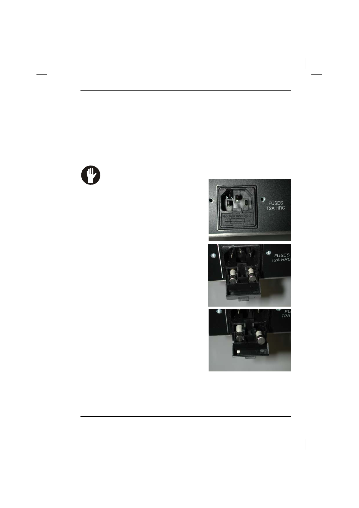
Section 4 - 700/900 Series Ventilators
4. Routine Maintenance
4.3 Other Maintenance
Occasionally, maintenance may be required on items that are not covered by
periodic routine maintenance tasks.
Annual maintenance checks are to be performed by a qualified technical engineer.
4.4 Exchanging Fuses
WARNING: The use of incorrectly rated fuses constitutes a fire
hazard. Replace the two fuses only
with the correct type and rating of
fuse.
1. At the rear of the machine in the bottom left
hand corner is located the mains outlet.
2. There are two small tabs located here.
3. Pull these tabs toward you using finger and
thumb.
4. Fuses are now visible and can be exchanged.
5. Push compartment back into outlet
6. If the fuse fails a second time contact a
technical engineer.
Figures 6/7/8 Exchanging
fuses
700/900 Series Ventilators User Manual 85
Page 88

4. Routine Maintenance
Section 4 - 700/900 Series Ventilators
4.5 Cleaning and Sterilization
WARNING: Ingress of liquid into the control unit may damage
the unit or result in injury to personnel. Ensure that no liquid
enters the control unit, and always disconnect the unit from the
mains electrical supply before cleaning.
WARNING: Do not clean the LCD Screen with liquid.
Use only a dry, soft, lint-free cloth.
4.5.1 Ventilator Surfaces
Clean the outside surfaces of the ventilator by wiping them with a damp cloth
soaked in a mild detergent solution. Ensure that all residues are removed after
cleaning by wiping with a dry, lint-free cloth. Never use abrasive cleaning material,
particularly on the screen.
The ventilator surfaces are not scratch-resistant. Do not use
abrasive cleaning agents otherwise damage to the surfaces will
result.
4.5.2 Pop-off Valve Seat
1. Remove the bellows housing and bellows.
2. Loosen the black thumbscrews and remove the pop-off valve.
3. Clean the valve seat carefully using a soft, lint-free cloth.
4. There is an O-ring located in the bellows base, (see opposite) which provides a
seal with the pop-off valve. After cleaning, check that the O-ring is in place, as
the ventilator cannot function correctly without it.
If the valve seat is damaged, the pop-off valve will leak and may
cause serious malfunction. Take care not to damage the
precision-molded surface of the valve seat while cleaning. Never
use a hard object or abrasive detergent. Use only a soft, lint-free
cloth.
86
700/900 Series Ventilators User Manual
Page 89
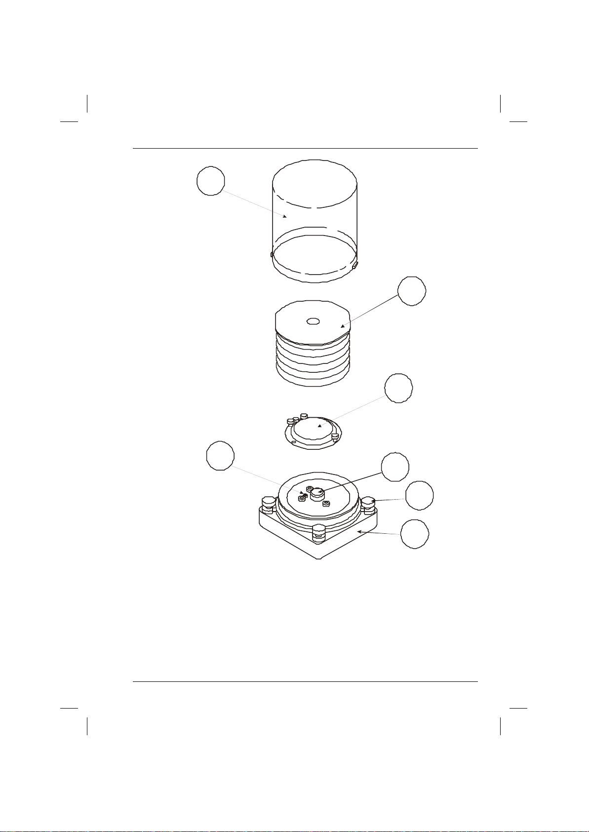
Section 4 - 700/900 Series Ventilators
BACDF
E
G
Figure 9 Removing the Pop-off Valve
4. Routine Maintenance
A Cover E Bellows Base
B Bellows F Fixing Screws
C Pop-off valve G O-ring
D Valve seat
700/900 Series Ventilators User Manual 87
Page 90
4. Routine Maintenance
Section 4 - 700/900 Series Ventilators
4.5.3 Patient Airway Flow Sensor
The flow sensor can be hand or machine washed and disinfected with a suitable
disinfectant. Steam autoclaving must not exceed 134oC. The sensor can be
sterilized with ethylene oxide.
To clean the flow sensor, pour distilled water slowly and gently into the outlet
port. Water must not be directed into this port under pressure.
Chemical decontaminants or liquid sterilization agents will
damage the sensor and must NOT be used for cleaning or
sterilizing. If autoclaving the sensor, the autoclave must only be
used with distilled water.
Blanking cap on patient flow sensor is NOT autoclavable.
4.5.4 Bellows
Only the bellows base and the parts inside the bellows require
sterilization.
To avoid damage to the equipment:
Peak sterilization temperature must not exceed 134ºC.
Do not sterilize the control unit.
Gas sterilization should be followed by quarantine in a wellventilated area to allow dissipation of residual absorbed gas.
Follow the sterilization agent manufacturer's instructions.
The expiratory valve must be disassembled prior to autoclaving
to prevent the occurrence of clamping stresses.
The pediatric adapter, can be sterilized but must not be
autoclaved.
1. Pull absorber forward to disconnect the bellows base.
2. Loosen the two thumb screws retaining the bellows base and remove the
bellows base and housing from the control unit.
3. Remove the pop-off valve and pediatric bellows adapter (if fitted) and clean
and sterilize them separately.
4. Perform sterilization as specified in the table opposite.
88
700/900 Series Ventilators User Manual
Page 91
Section 4 - 700/900 Series Ventilators
4. Routine Maintenance
4.5.5 Methods of Sterilization
ITEM METHOD
Bellows* Gas1, liquid2, autoclave3
O-ring Gas1, liquid2, autoclave3
Bellows housing* Gas1, liquid2, autoclave3
Bellows base* Gas1, liquid2, autoclave3
Pop-off valve Gas1, liquid2 autoclave3
Pop-off diaphragm Gas1, liquid
2
autoclave3
Control unit Do not sterilise
Patient Airway Flow sensor Gas1, liquid2, autoclave 134o C max
N.B. The white plastic blank is not
Autoclavable.
Notes:
1. Ethylene oxide, 54°C max.
2. Eg. Cidex, Sporicidin, Sonacide.
3. Steam autoclave, 134°C max.
The autoclavable bellows base has a 30 mm diameter exhaust
port, the canister is smokey grey with ribs around it and there
are four large lugs. The rubber bellows has a plastic coated
metal top plate. Older type canisters are clear with only two
lugs. Old style bellows have a solid plastic top plate.
700/900 Series Ventilators User Manual 89
Page 92

4. Routine Mainte-
Section 4 - 700/900 Series Ventilators
Notes
90
700/900 Series Ventilators User Manual
Page 93

Section 5 - 700/900 Series Ventilators
5. Troubleshooting
5. Troubleshooting
The table below describes faults, their probable causes and recommended
corrective actions. If a fault persists, do not use the ventilator. Contact your Blease
service representative.
FAULT CAUSE ACTION
MAINS FAIL
alarm activated
when
ventilator
switched on.
Bellows cannot
be filled, or
collapses.
Bellows
progressively
deflates
despite normal
fresh gas flow.
Power cable not connected.
Defective mains supply.
Blown Fuse(s).
Breathing system hose
disconnected or leaking.
Broken bellows base.
Defective or detached
bellows.
Damaged pop-off valve.
Missing or defective O-ring.
Breathing system leak.
Open or defective pop-off
valve.
Damaged pop-off valve seat.
Damaged bellows base O-ring.
Damaged bellows base.
Connect power cable.
Check supply.
Exchange fuses.
Check hose. Exchange if
damaged.
Exchange bellows base.
Check bellows. Exchange if
damaged.
Exchange pop-off valve.
Fit or exchange O-ring.
Check patient connections
Exchange hose.
Exchange pop-off valve.
Exchange pop-off valve seat.
Exchange O-ring.
Exchange bellows base.
Check patient connections.
Tidal volume
incorrect or
inconsistent.
700/900 Series Ventilators User Manual 91
Missing pop-off valve seat
O-ring.
Partially detached or
defective bellows.
Damaged pop-off valve disc or
seat.
Fit O-ring.
Check bellows. Change if
damaged.
Exchange pop-off valve disc or
seat.
Page 94

5. Troubleshooting
FAULT CAUSE ACTION
Section 5 - 700/900 Series Ventilators
Irregular rate when
electro-cautery is
used.
PRESSURE LOW
alarm activated but
ventilation normal.
Tidal volume not
delivered and
PRESSURE
CYCLING alarm
activated.
SUPP GAS LOW
alarm blinks on each
breath.
Unwanted PEEP and
overfull bellows.
BATT LOW alarm
activated.
Defective mains
supply outlet.
Defective eletro-cautery.
Disconnected or kinked
pressure pick-up tubing.
Pressure limit set too low.
Obstructions in breathing
system or bellows drive
Incorrect drive gas supply
pressure.
Kinked or obstructed drive
gas supply hose.
Defective or poorly
regulated scavenging
system.
Partially obstructed
exhaust.
High Gas Flow
Defective or discharged
battery.
Change mains supply
outlet.
Check and repair
electro-cautery.
Reconnect tube or
remove kink.
Exchange tube if
damaged.
Change pressure limit.
Remove obstructions.
Check drive gas supply
pressure.
Reconnect hose or
remove kink.
Exchange hose if
damaged.
Adjust or exchange
scavenging system.
Remove the obstruction.
Charge battery.
Exchange if defective.
92
700/900 Series Ventilators User Manual
Page 95

Section 6 - 700/900 Series Ventilators
6. Appendices
6.1 Performance Data
CONTROL/PARAMETER RANGE/VALUE
Input power 90 – 265 VAC
Frequency 50/60 Hz
Current 500 mA max.
Power consumption 50 VA
Input supply gas 40 psig to 101 psig at 120 lpm
Adult bellows size 1600 ml
Adult minute volume 0.3 lpm to 25 lpm
Adult tidal volume 20 ml to 1500 ml
Pediatric minute volume 0.3 lpm to 25 lpm
Pediatric tidal volume 20 ml to 1500 ml
6. Appendices
Rate 2 bpm to 99 bpm
I:E ratio 2.0:1 to 1:5.0
Pressure limit control:
Adult
Pediatric
Maximum working pressure range 5 cm H2O to 70 cm H2O
Altitude (self-compensating) 0 to 3,000 m
Compliance (see note)
Adult
Pediatric
PEEP 3 cm H2O to 20 cm H2O
10 cm H2O to 70 cm H2O
10 cm H2O to 50 cm H2O
Calibrated as maximum % of set volume
700/900 Series Ventilators User Manual 93
Page 96

6. Appendices
Section 6 - 700/900 Series Ventilators
6.1.1 Notes on Performance Data
Both adult and pediatric compliance are increased by approximately 0.6 ml/cm
H2O when the ventilator bellows is separated from the control unit by 1.5 m of
22 mm tubing. This would be the case when the ventilator is installed as part of a
Blease Anesthesia work station where the bellows is behind the absorber.
6.2 Dimensions
Height 185 mm
Width 310 mm
Depth 310 mm (case)
Weight 10kg
94
700/900 Series Ventilators User Manual
Page 97

Section 6 - 700/900 Series Ventilators
6. Appendices
6.3 Factory Default Settings
The tables below show the default settings at start-up.
These are default settings and can be changed to suit by going to the defaults
menu.
6.3.1 Volume Control Defaults at Startup
ADULT 500 12 1:2.0 50 1/25 4/50
VOL
(ML)
RATE
(BPM)
I:E
PRESSURE
LIMIT
(cm H2O)
MINUTE VOL
ALARM
LO / HI
PRESS
ALARM
LO / HI
PED 150 15 1:2.0 50 1/25 4/50
6.3.2 Pressure Control Ventilation Defaults at Start-up
VENT PRESS
(cm H2O)
RATE
BPM
PRESS
ALARM
LO /HI
MINUTE
VOL ALARM
LO/HI
ADULT 15 12 4/18 1/25
PED 15 15 4/18 1/25
6.3.3 Pressure Support Defaults at Start-up
ADUL
T
PED 2/99 1/25 4/50 5 10 15
RATE
ALARM
LO / HI
2/99 1/25 4/50 5 10 50
MINUTE VOL
ALARM
LO / HI
PRESSURE
ALARM
LO / HI
Trigger Support Pressure Limit
700/900 Series Ventilators User Manual 95
Page 98

6. Appendices
Section 6 - 700/900 Series Ventilators
6.3.4 SIMV + PSV Defaults at Start-up
SUPPORT
ADULT 10 50 2/99 1/25 4/50 12 500 OFF 2.0
PED 10 15 2/99 1/25 4/15 15 150 OFF 1.0
PRESS
(cm
H2O)
PRESS
LIMIT
(cm
H2O)
RATE
ALARM
LO / HI
MINUTE
VOL
ALARM
LO / HI
PRESS
ALARM
LO / HI
BPM VOLUME PEEP I-TIME
6.4 Fixed Features
COMPLIANCE FRESH
VOLUME
CONTROL
PRESSURE
SUPPORT
SIMV + PSV
PRESSURE
CONTROL
GAS
PEEP OXYGEN
Meas/Set Meas
Meas/Set Meas
Meas/Set Meas
Meas/Set Meas
96
700/900 Series Ventilators User Manual
Page 99

Section 6 - 700/900 Series Ventilators
6.5 Mode Dependent Features
6. Appendices
VOLUME
CONTROL
PRESSURE
SUPPORT
SIMV +
PSV
PRESSURE
CONTROL
SIGH PAUSE
PRESSURE
SUPPORT
TRIGGER
PRESSURE
SUPPORT
PRESSURE
ALWAYS ALWAYS Meas Meas Meas Pressure
ALWAYS ALWAYS Meas/
BPM VOL/
FLOW
Set Meas/set Set Pressure
Meas/set Meas/
set
Set IFLOW Set
I:E
set
PRESSURE
LIMIT
Limit
Limit
Pressure
Limit
Set
Pressure
700/900 Series Ventilators User Manual 97
Page 100

6. Appendices
Section 6 - 700/900 Series Ventilators
6.6 Associated Equipment and Accessories
Part Number Description
10110026 Adult bellows assembly complete PEEP
10110016 Bellows base assembly
83034 Adult bellows only
83035 Adult bellows cover only
80200026 Mains cable UK .5 m
80200027 Cordset connector lock UK
80200028 Mains cable US 2.5 m
80200029 Cordset connector lock US
80300026 T1A Fuse
81027 Corrugated Hose (17 mm x 200 mm)
ST2101 Corrugated tubing 42-in (22 mm)
700/900 Ventilator User Manual
98
700/900 Series Ventilators User Manual
 Loading...