

Page 1
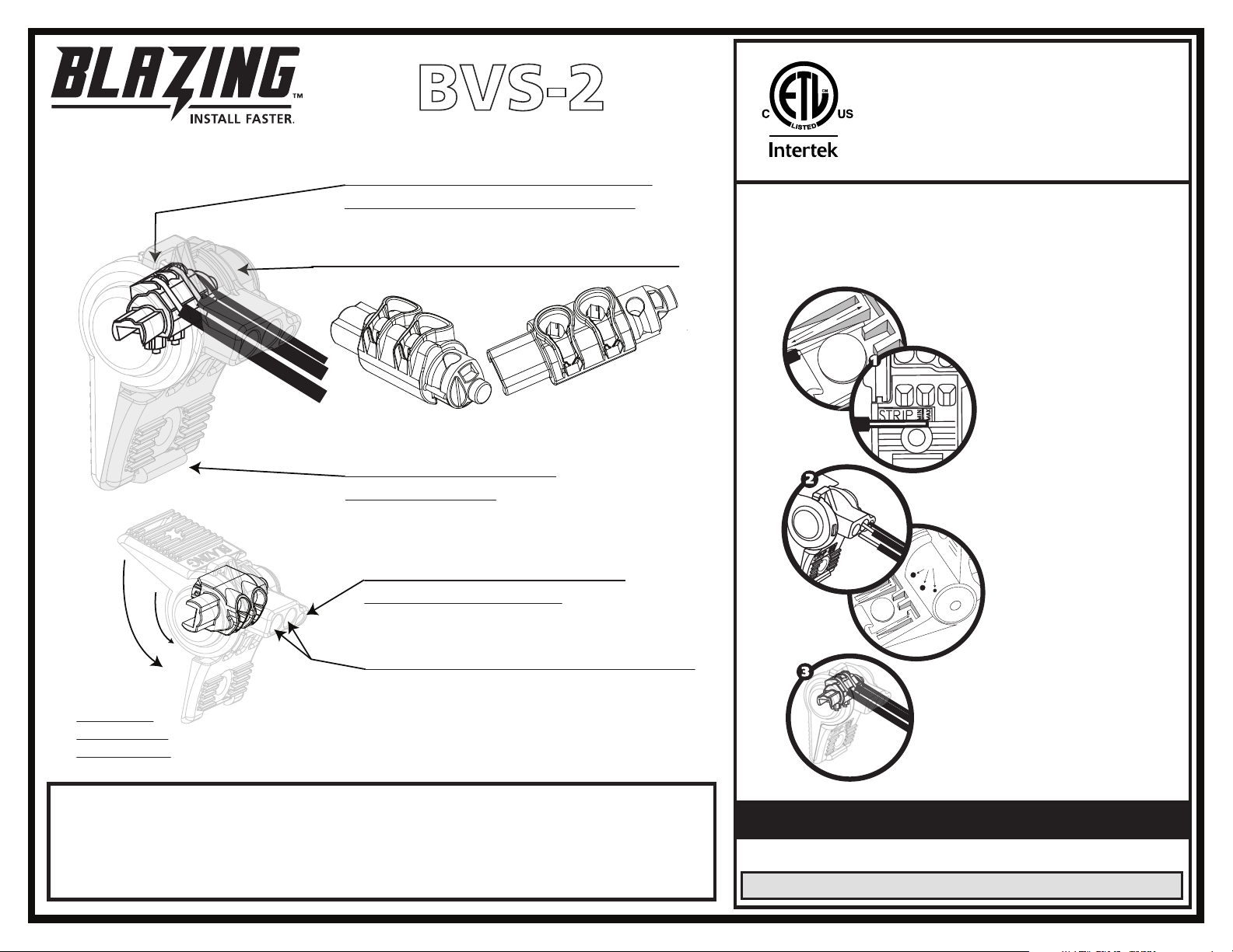
2 #14 Sol, 1 #18 Str AWG CU
Strip
Strip
Visible
Ends of Wires
Stri p
Stri p
600 Volts Max, 105°C Max
Closed Position
BVS-2
Wire torqued around metal insert;
provides excellent wire restraint
Wire Chamber filled with Silicone Grease
Over-hook Latch keeps
connector closed
One hole for #16, #18 or #20
solid or stranded wire
Two holes for #12 and #14 solid wire
Raintight, Watertight, Submersible
For Use in Damp & Wet Locations
486D Direct Bury Listed
Installation Instructions
Always use caution, turn off power. Use on electrical circuits
of 600 volts or less. Installation should always comply with
local and national electrical codes.
Step 1
Strip wires to 5/8”. Use
one of the strip guides
molded into the
connector for reference.
Pre-twist stranded
wires.
Step 2
Rotate handles fully
apart beyond 90
degrees. Insert stripped
wires into connector;
#12-#14 in the large
holes and #16-#20 in the
small hole. Exposed
ends of wires should be
visible through the clear
housing on the back.
As handles
rotate, metal
insert rotates
Open Position
For Multiple #18 or #20 Wire Combinations:
Strip all wires to 5/8”. Pre-twist stranded wires. Insert up to 3 solid or stranded
#18 or #20 wires into each large hole and 1 #18 or #20 solid or stranded in the small
hole. Hold wires in place while squeezing handles together until the latch snaps
shut. Up to 7 wires total in connector.
Step 3
Hold wires in place
while squeezing
handles together until
the latch snaps shut.
PACKAGING QTYS.
PART PACKAGE CARTON MIN. ORDER
BVS-2 20 100 100
 Loading...