

Page 1
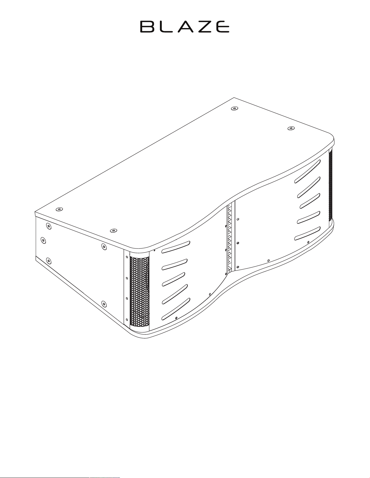
INSTALLATION MANUAL
CCA10i-BA Loudspeakers
Page 2
1. Introduction and Overview
1.1 Introduction
Thank you for purchasing a Blaze Audio CCA10i-BA loudspeaker. The CCA10i-BA is a constant curvature, arrayable
point source loudspeaker, designed for medium-sized venues to large distributed systems that require a exible and
scalable loudspeaker solution. Mounted horizontally with tight acoustic centres to minimize comb ltering, each
CCA10i-BA enclosure provides xed 20° vertical and 160° horizontal coverage. CCA10i-BA loudspeakers are designed
to be own with additional enclosures in vertical arrays.
The CCA10i-BA features a coaxial compression driver employing individual midrange and high-frequency polymer ring diaphragms.
The driver delivers extremely wide bandwidth from 420 Hz – 18,000 Hz. For low frequencies, dual 10” high-excursion drivers deliver
efcient and accurate bass down to 52 Hz (-3 dB) with minimal distortion and power compression.
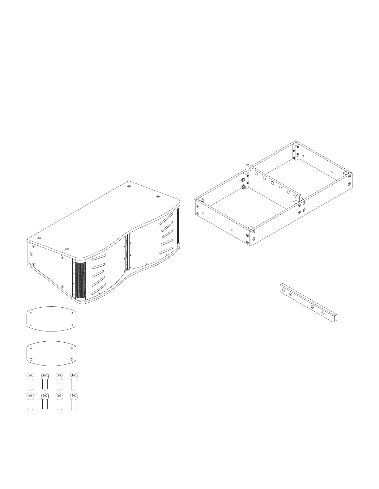
1.2 CCA10i-BA Pack Contents
In addition to this installation manual, Each CCA10i-BA package
contains the items identied and illustrated below.
1 x CCA10i-BA
loudspeaker
Rigging Grid (aluminum)
Note: A steel Rigging Grid is available to order for installations where
specic structural and regulatory demands require it.
Rigging Extension Arm
2 x CCA10i-BA Rigging Plates
8 x M10x30 hex head bolts
1.3 Rigging Accessories
Rigging accessories that enable single or multiple CCA10i-BA
loudspeakers to be own are available separately from Blaze
Audio. The rigging accessories are identied and illustrated
alongside. Instructions on the use of the rigging accessories can
be found in Section 2.3 of this manual.
Note: Rigging accessories are supplied complete with the appropriate
bolts, nuts, washers and other necessary attachment items.
Page 3
2. Applications and Deployment
2.1 Applications
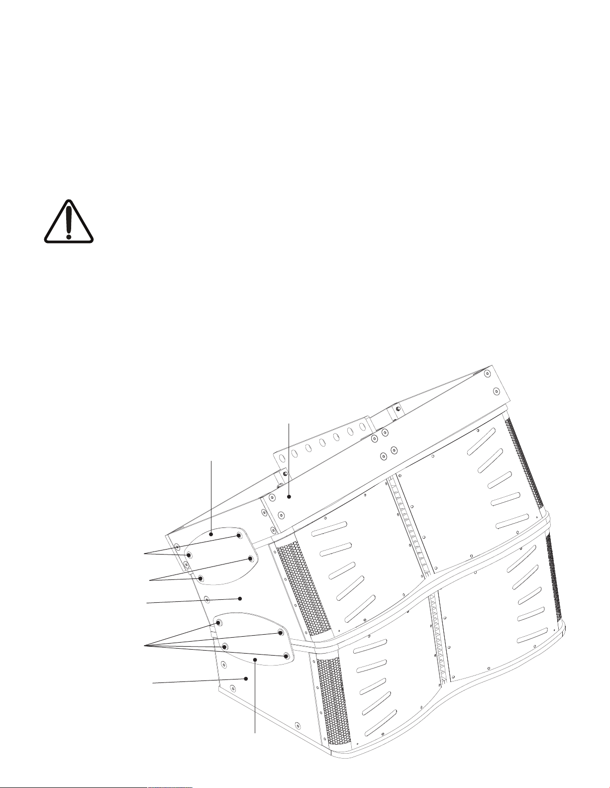
The CCA10i-BA can be congured as an individual point-source loudspeaker or in a vertical array with multiple
CCA10i-BA loudspeakers. Integrated rigging enables easy and secure box-to-box deployment. Flying CCA10i-BA
loudspeakers, requires the CCA10i-BA Rigging Grid. This separately sold item enables the suspension up to four
(4) CCA10i-BA loudspeakers. Arrays of greater than four CCA10i-BA loudspeakers are possible but will require
customized Blaze Audio rigging accessories. The basic CC10i-BA rig, array and suspension principle is illustrated below
however for all supported rigging congurations, see the chart in Section 2.3.
IMPORTANT: In all cases, when rigging
loudspeakers together, attach the bottommost
unit to the loudspeaker directly above it, moving
up the array to the topmost unit, ending with the
Rigging Grid.
WARNING: The CCA10i-BA weighs 83lbs / 37.65kg. Use proper
lifting techniques to avoid serious injury. Please see Section 2.4
for Maximum Suspended Load.
Basic CCA10i-BA Array Assembly
Note: Left hand side of array shown.
Rigging Plate and Grid attachment must be
duplicated on the right hand side.
Rigging Plate
Rigging Grid
WARNING: When assembling or disassembling arrayed
loudspeakers, make sure that all components are properly
supported throughout the entire process to avoid damage or
injury.
WARNING: To ensure secure attachment, verify that the
loudspeakers are properly aligned for box-to-box vertical
attachment. If loudspeakers are not properly aligned, physical
damage, and personal injury may occur. The top of each
loudspeaker must be parallel to the bottom of the unit above it.
For suspension, the topmost unit must be securely attached to
the CCA10i-BA Rigging Grid.
2 x M10 x 30 hex head
+ washer and nut
2 x M10 x 30 hex head
CCA10i-BA #2
4 x M10 x 30 hex head
CCA10i-BA #1
Rigging Plate
Page 4

2. Applications and Deployment
2.2 Important Safety Instructions
WARNING: Failure to observe the following safety precautions may result in severe injury or death.
Installations such as described in this guide should only be attempted by a trained professional.
• Read these instructions.
• Keep these instructions.
• Heed all warnings.
• Follow all instructions.
• Before installing or suspending any CCA10i-BA loudspeaker,
inspect all hardware, the enclosure, and associated equipment
for damage. Missing, corroded, or deformed components, or
components without correct load ratings, could signicantly
reduce the strength of the installation or placement and should
immediately be repaired or replaced.
• Always make sure that the structure the loudspeaker is to be
suspended from has been approved by the building or structural
engineer and will support the weight of all the components
of the speaker system including speakers, speaker cable, wire
rope, etc.
• Consult a licensed professional structural engineer regarding
physical equipment installation.
• Do not suspend loudspeakers directly over people.
• Use only hardware that is rated for the load conditions of
the installation and that allows for a possible short-term,
unexpected overload. Never exceed the rating of the hardware
or equipment.
• Blaze Audio strongly recommends that the system be inspected
at least once a year and logged. If any sign of weakness
or damage is detected, remedial action should be taken
immediately.
• All installation crew members must be trained for loudspeaker
rigging and mounting.
• Make sure that all relevant health and safety regulations
are known, are followed by the installation crew, and follow
applicable local laws. Local government ofces can help with
this information.
• Suspended installations must be completed or supervised by a
certied rigger.
• The system should be designed so that it is a static suspension.
There should be no dynamic or shock loading.
• Personal protective equipment (hard hats, steel-toed footwear,
safety glasses, etc.) should be always worn by the installation
crew.
• If called for in the design, make sure all installation personnel
are trained to work at height and have certications for scissor
lifts, theatrical hoists, etc.
• Make sure all lifting equipment (slings, span-sets, deck chain,
scaffolding, etc.) is in good working order. Thoroughly inspect all
components prior to use.
• Inspect all the components associated with the project
for damage before assembly. Any parts with damage or
suspected damage should not be used. Contact the component
manufacturer for replacement parts if necessary.
• Keep a tidy workplace. Do not leave tools, rigging items, etc., on
top of loudspeakers during installation. Loose items can fall and
cause injury.
• Never leave the system unattended during the installation
process. Make sure that the workspace is isolated from
public access. No one should be allowed to pass beneath the
loudspeakers during installation.
• Do not suspend any other components or loudspeakers other
than the supported congurations described in this manual.
• If secondary steel safeties are required, they should be installed
once the entire system is at operating height and before public
access is allowed.
Page 5
2. Applications and Deployment
2.3 Rigging Instructions
CCA10i-BA loudspeakers feature integrated rigging hardware. Use of the rigging hardware is similar whether multiple
CCA10i-BA loudspeakers are to be joined, or are to be attached to a CCA10i-BA Rigging Grid.
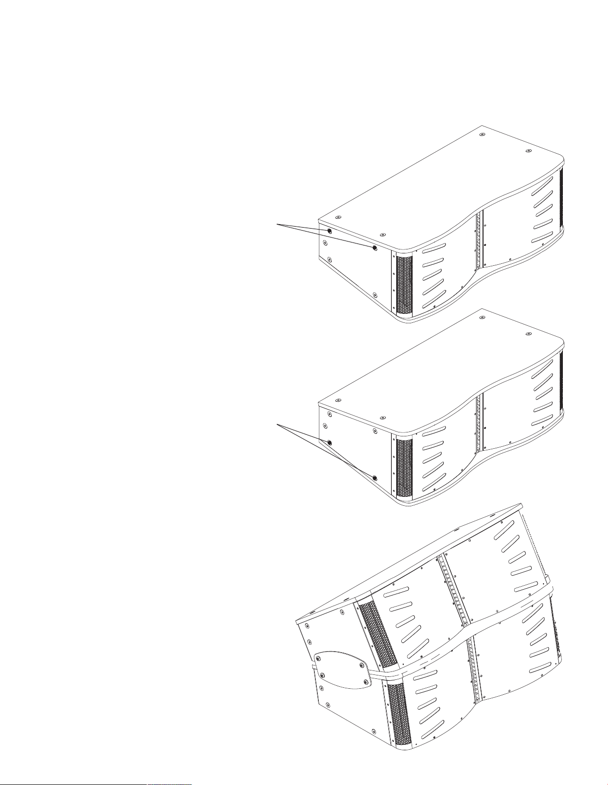
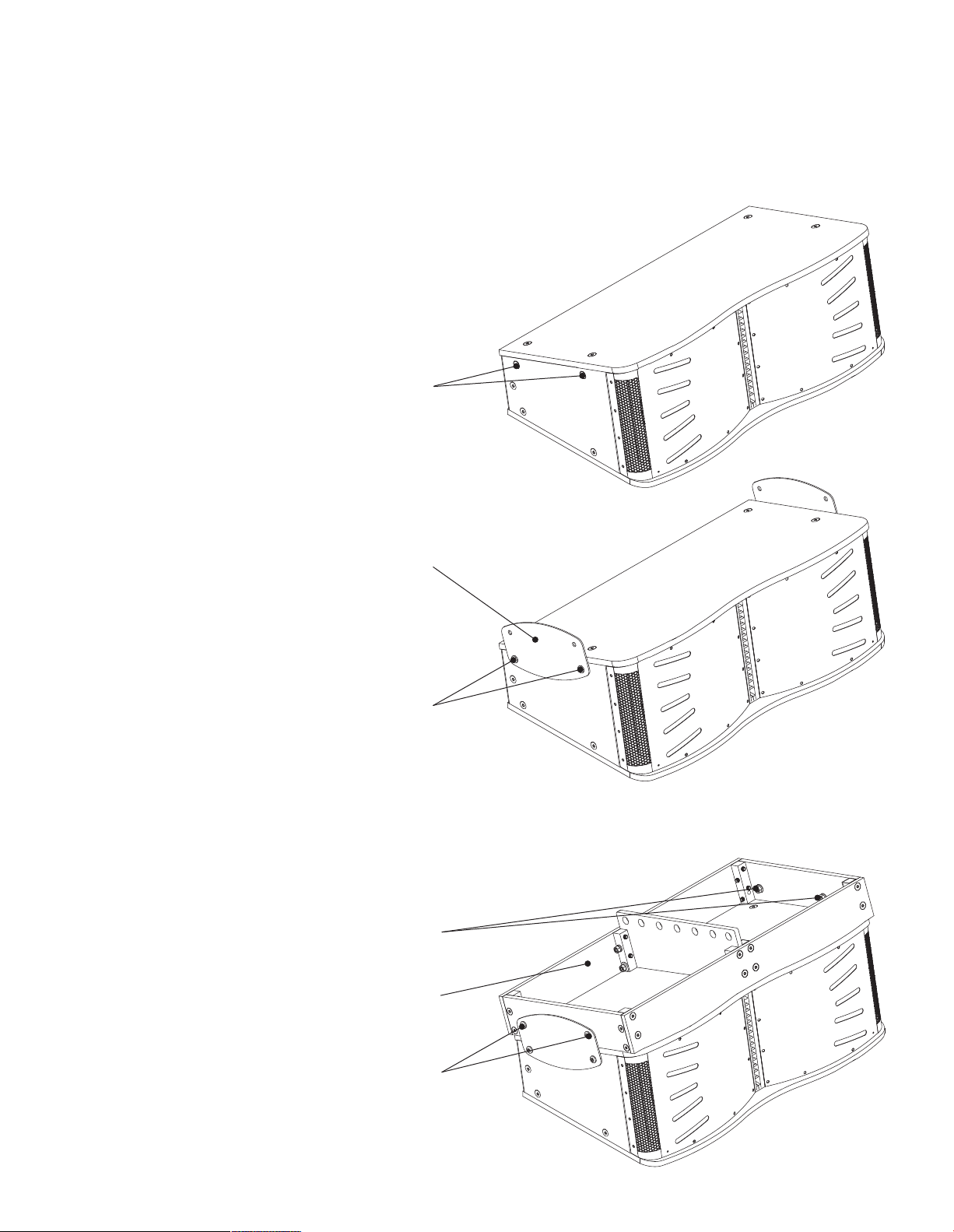
2.3.1 Connecting One CCA10i-BA to Another
Step 1. On the bottom CCA10i-BA loudspeaker remove the two
upper-most countersunk M10 bolts on the left and right
sides. The bolts can be discarded.
Remove and discard
(repeat on other side)
Step 2. On the top CCA10i-BA loudspeaker remove the two
lower-most countersunk M10 bolts on the left and right
sides. The bolts can be discarded.
CCA10i-BA #1 (bottom)
Remove and discard
(repeat on other side)
Step 3. Align the top CCA10i-BA loudspeaker over the bottom
CCA10i-BA loudspeaker and install the provided Rigging
Plates plates between the two enclosures on the left and
right sides. Secure the Rigging Plates using the supplied
M10 hex head bolts.
CCA10i-BA #2 (top)
Page 6
2. Applications and Deployment
2.3 Rigging Instructions
CCA10i-BA loudspeakers feature integrated rigging hardware. Use of the rigging hardware is similar whether multiple
CCA10i-BA loudspeakers are to be joined, or are to be attached to a CCA10i-BA Rigging Grid.
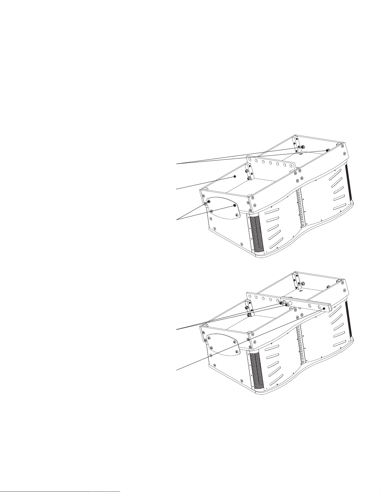
2.3.2 Connecting a CCA10i-BA to a Rigging Grid
Step 1. Remove the two upper-most countersunk M10 bolts on
the loudspeaker on both the left and right sides. The bolts
can be discarded.
Remove and discard
(repeat on other side)
Step 2. Attach one of the supplied Rigging Plates to each side
of the enclosures. Secure the Rigging Plates using the
supplied M10 hex head bolts.
Rigging Plate
(pair on other side)
2 x M10 x 30 hex head bolts
(repeat on other side)
Step 3. Place the Rigging Grid on the top of the loudspeaker and
align its attachment holes with the corresponding holes in
the left and right Rigging Plates. Secure the Rigging Grid
to the Rigging Plates using the supplied M10 hex head
bolts with the supplied lock washers and nuts.
2 x M10 lock washers and nuts
(repeat on other side)
Rigging Grid
2 x M10 x 30 hex head bolts
(repeat on other side)
Note: A steel Rigging Grid is available to order for installations where
specic structural and regulatory demands require it.
Page 7
2. Applications and Deployment
2.3 Rigging Instructions
CCA10i-BA loudspeakers feature integrated rigging hardware. Use of the rigging hardware is similar whether multiple
CCA10i-BA loudspeakers are to be joined, or are to be attached to a CCA10i-BA Rigging Grid.
2.3.3 Attaching the Rigging Grid Extension Arm
The Rigging Grid Extension Arm can be used when it is required
to alter the vertical angle of suspended CCA10i-BA loudspeakers.
Step 1. Attach a Rigging Grid as described in Section 2.3.3 of this
manual to a single, or an array of multiple, CCA10i-BA
loudspeakers.
2 x M10 lock washers and nuts
(repeat on other side)
Rigging Grid
2 x M10 x 30 hex head bolts
(repeat on other side)
Step 2. Position the Rigging Grid Extension Arm on the central
spine of the Rigging Grid at either the front or the back of
the assembly depending the suspension angle adjustment
required. Secure the Rigging Grid Extension Arm using
the supplied clevis and cotter pins.
2 x Clevis and Cotter Pins
Rigging Extension Arm
Page 8
2. Applications and Deployment
2.4 Suspending CCA10i-BA Loudspeaker Arrays
WARNING: Consult a professional mechanical or structural engineer, licensed in the jurisdiction of the
sound system installation, to review, verify, and approve all attachments to the building or structure.
Employ the services of a certied, professional rigger for hoisting, positioning and rigging the equipment
to the supporting structure. Improper suspension can lead to serious damage, injury, or death.
NEVER SUSPEND LOUDSPEAKERS DIRECTLY ABOVE THE AUDIENCE
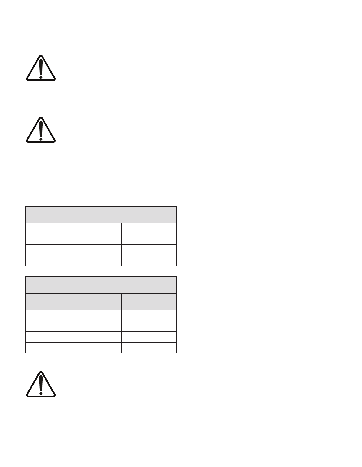
The tables below show the individual
CCA10i-BA component weights and the
total weights for arrays up to the maximum
recommended conguration of four CCA10i
- BA loudspeakers. Deploying loudspeakers
that exceed the maximum conguration can lead to
serious damage, injury, or death. Blaze Audio has tested
the congurations below for safety. Please note that the
structure from which CCA10i-BA loudspeaker arrays are
suspended must be able to support that total weight.
CCA10i-BA Individual Component Weights
CCA10i-BA Loudspeaker
Rigging Plate 1.6 lbs (0.726 kg)
Rigging Grid (Aluminium) 32 lbs (14.5 kg)
Rigging Grid Extension Arm 7.2lbs (3.26kg)
Total CCA10i-BA Array Weights
Number of Suspended CCA10i-BA Array Weight
1 118.2 lbs (53.61 kg)
2 204.4 lbs (92.71 kg)
3 291 lbs (132 kg)
4 377.2 lbs (171.1 kg)
WARNING: All CCA10i-BA rigging and
rigging accessories are rated for a 10:1 load.
Structural suspension supports must also be
rated for a 10:1 load.
83 lbs (37.65 kg)
Page 9
3. Connection and Amplication
3.1 CCA10i-BA Input Connections
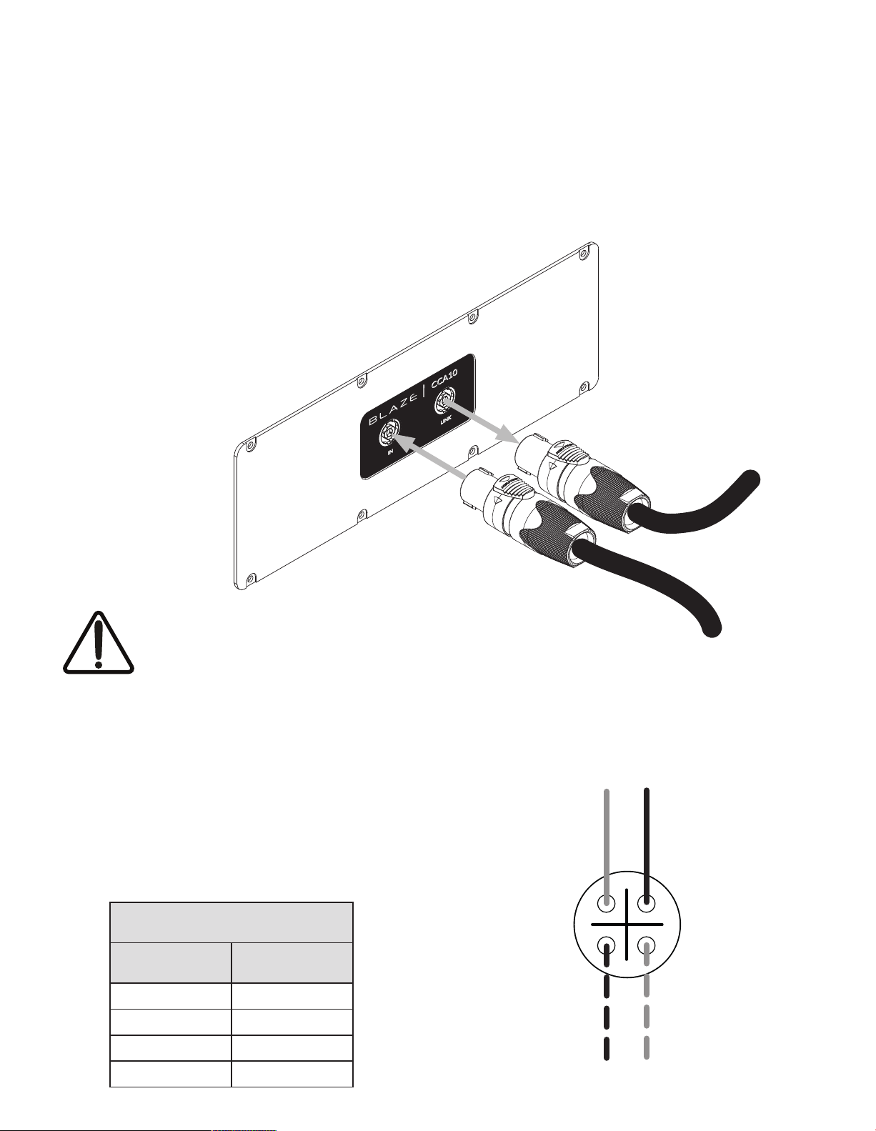
The CCA10i-BA is tted with two Neutrik NL4 Speakon sockets on its rear panel. One socket is for input and the
second is for pass-trough. The “Input” is used for connection directly to the Blaze PowerZone Connect 3004 Amplier
and the “Link” can be used to connect in parallel to a second CCA10i-BA. Both Neutrik sockets are wired in a bi-amp
conguration and use all four pins. The pin connections are listed in the table below.
3.1.1 CCA10i-BA Connections
The CCA10i-BA loudspeaker connection panel
carries two, four-pole Neutrik Speakon sockets. An
INPUT socket and a LINK output socket. Connect
the INPUT socket to a pair of Blaze PowerZone
Connect 3004 amplier outputs. Optionally
connect the LINK socket to the INPUT socket of a
second CCA10i-BA loudspeaker.
Optional “Link” connection to a
second CCA10i-BA loudspeaker
NOTE: While the use of the “Link” connector for
a second CCA10i-BA loudspeaker is supported,
to maintain full power to the loudspeaker and
retain the ability to adjust amplier parameters
for loudspeakers independently, Blaze does not
normally recommend this mode of use.
3.1.2 CCA10i-BA Connections Signal Routing
CCA10i-BA loudspeaker connections are intended for bi-amp
conguration where a each loudspeaker is powered by two
amplier channels – one for the twin bass drivers and one for the
horn loaded compression mid/high frequency driver. The fourpole INPUT and LINK sockets are wired to enable this connection
scheme as indicated in the following table and diagram.
CCA10i-BA Socket Connections
Signal Routing Connection Pin
LF (-) 1 (-)
LF (+) 1 (+)
HF (-) 2 (-)
HF (+) 2 (+)
Neutrik Speakon NL4 Pins
Bass drivers
(LF) negative (-)
12+
Mid/high driver
(HF) positive (+)
Connect to Blaze PowerZone
Connect 3004 amplier outputs
Bass drivers
(LF) positive (+)
1+
2-
Mid/high driver
(HF) negative (-)
Page 10
3. Connection and Amplication
3.1.3 CCA10i-BA Amplier Connections
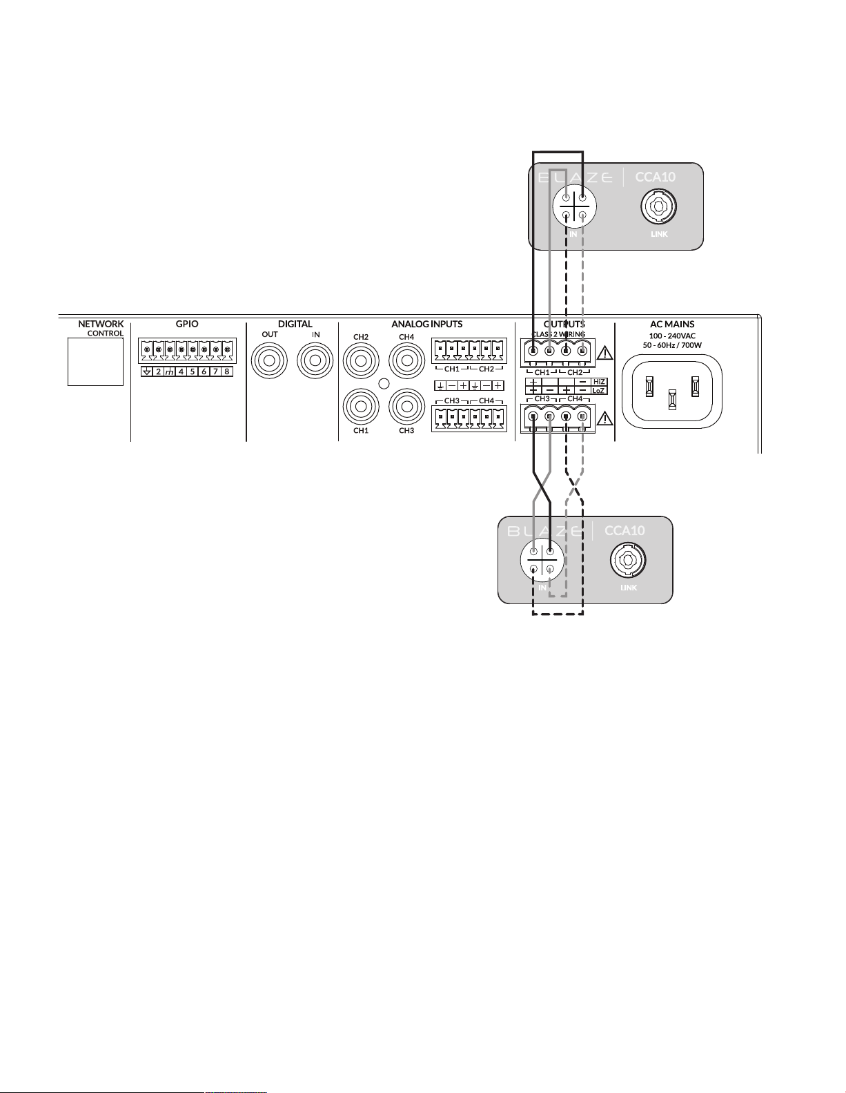
CCA10i-BA loudspeakers are intended to be paired with the
Blaze PowerZone Connect 3004 amplier. The PowerZone
Connect 3004 incorporates the DSP equalisation facilities
required to optimise the loudspeaker’s acoustic performance. The
PowerZone Connect 3004 is a four channel power amplier able
to drive two CCA10i-BA loudspeakers. It is not recommended
that more than two CCA10i-BA loudspeakers are connected to a
single PowerZone Connect 3004 amplier.
1-2+1+
2-
CCA10i-BA loudspeaker and PowerZone 3004 amplier
connections are illustrated in the diagram.
Note: The Blaze PowerZone Connection 3004 Installation Manual,
available for download from the Blaze website (blaze-audio.com),
contains comprehensive amplier installation and operational
information.
1-2+1+
2-
Page 11
3. Connection and Amplication
3.2 PowerZone Connect Amplier Equalization Proles
The Blaze PowerZone Connect 3004 amplier incorporates DSP based loudspeaker equalization, accessed via a web
page interface, that enables precongured lter and equalization presets to be applied to its speaker outputs. A preset
for CCA10i-BA loudspeakers is available for download from the Blaze website and must be used for correct speaker
performance. The procedure for downloading and applying speaker presets is described in the following paragraphs.
3.2.1 PowerZone Control Network Connection
In order to install the CCA10i-BA speaker preset les, the
PowerZone Connect 3004 amplier requires either a wired or
wireless connection via a TCP/IP network, or to connect via its
own wireless access point, to a computer or mobile device from
which speaker preset les can be uploaded. Internet access for
speaker preset le download is also required.
Note: The PowerZone Connect 3004 amplier Quick Start Guide
and Installation Manual documents cover network connection and
can be downloaded from the Blaze website: https://blaze-audio.com/
support/#Manuals
3.2.2 Speaker Preset Download and Application
Follow the steps below to download and apply the appropriate
CCA10i-BA speaker preset to each amplier output.
Step 1. Using a computer or mobile device, visit the Blaze website
(blaze-audio.com/products/speakers/cca10/) and select
the speaker preset les for download.
NOTE: The speaker preset
les will download in a
compressed .zip archive
format. Expand the .zip
archive and store the les in
an appropriate location on
the download device.
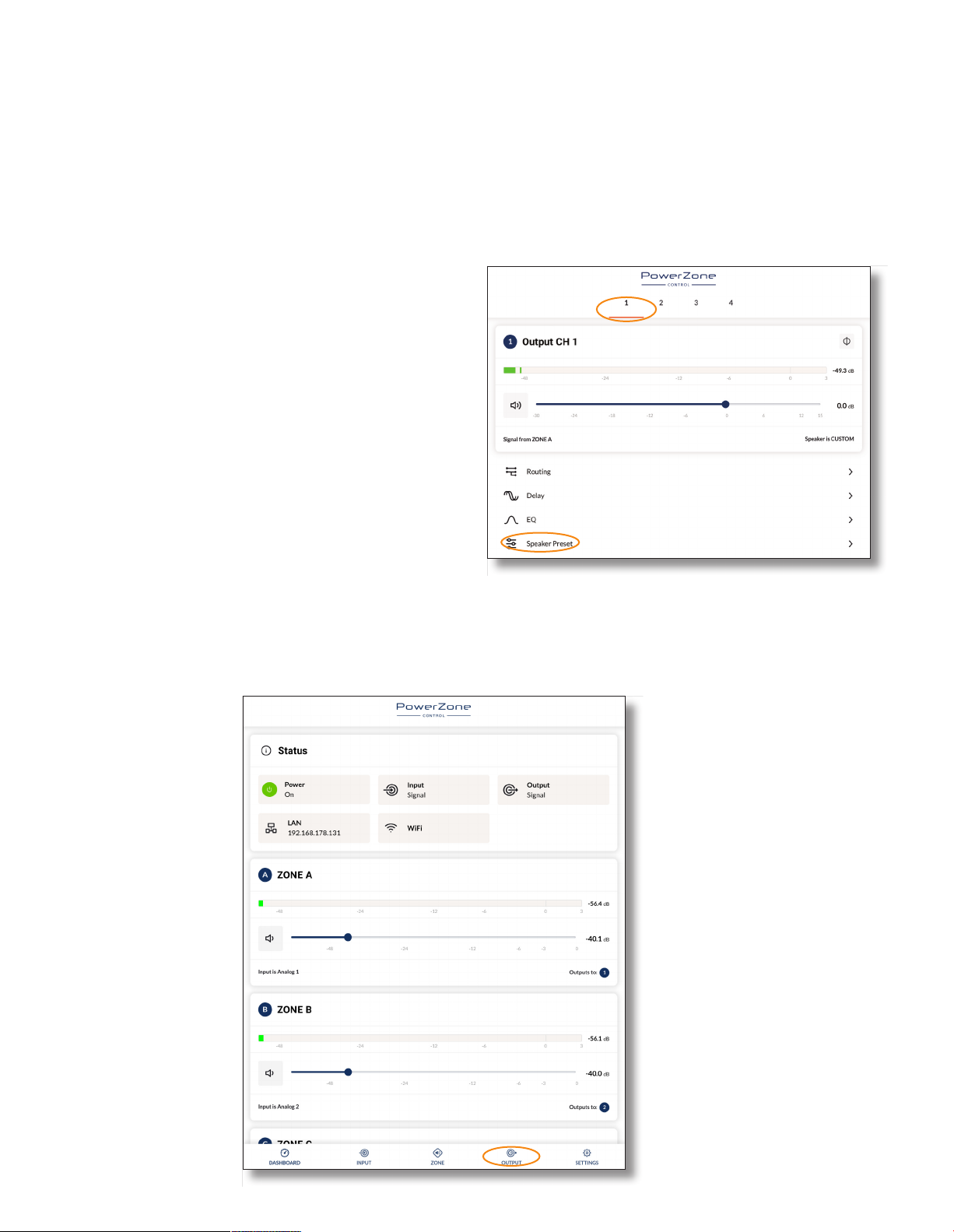
Step 2. On the computer
or mobile device,
navigate to the
PowerZone
Connect 3004
amplier web
interface and select
the Output tab.
Step 3. From the Output page select the Output 1 tab at the top
of the display and then select the Speaker Preset menu
option.
NOTE: The exact appearance and layout
of the amplier web interface may vary
slightly depending on the device and
browser in use.
Page 12
3. Connection and Amplication
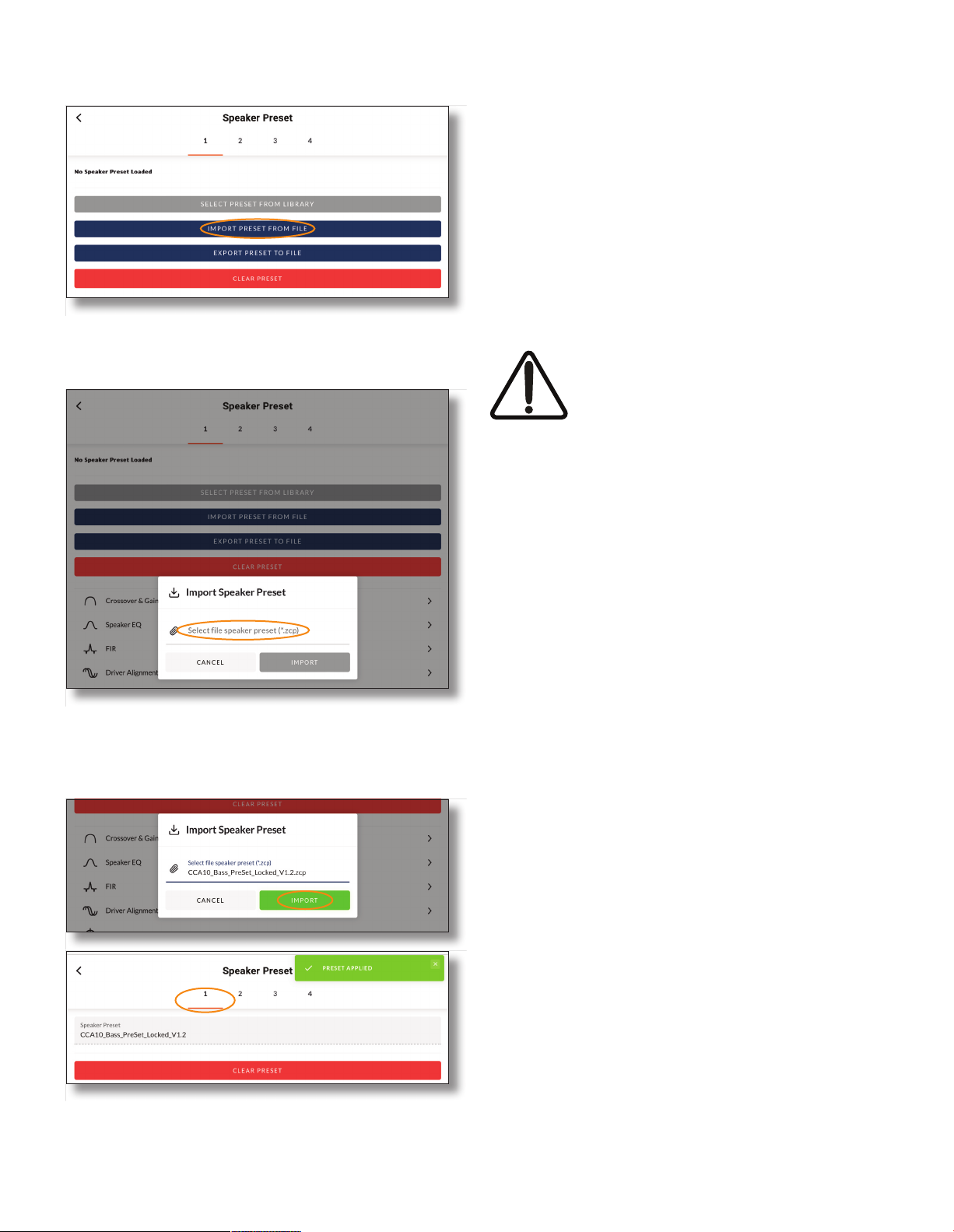
Step 4. Selecting IMPORT PRESET FROM FILE will open the
Speaker Preset Import pop-up box that provides the
option to choose a preset le.
Step 7. With the appropriate speaker preset le (CCA10_Bass_
PreSet_Locked_V1.2.zcp ) applied to amplier Output 1,
repeat Step 2 to Step 6 for the three remaining amplier
outputs. The appropriate speaker preset les for each
output are:
Output 2: CCA10_High_PreSet_Locked_V1.2.zcp
Output 3: CCA10_Bass_PreSet_Locked_V1.2.zcp
Output 4: CCA10_High_s_Locked_V1.2.zcp
NOTE: Amplier outputs are selected from the numbered tabs at the
top of the amplier interface Output page.
IMPORTANT: It is vital for the correct
operation of the CCA10i-BA loudspeaker
that the correct speaker preset le is
applied to each amplier output and that
the speakers are connected as described
in Section 3 of this manual.
Step 5. Browse the download device for the les downloaded in
Step 1 and select the le named:
CCA10_Bass_PreSet_Locked_V1.2.zcp
Select IMPORT.
Step 6. The speaker preset le will now be applied to amplier
Output 1.
Page 13
4. Technical Information
4.1 CCA10i-BA Specications
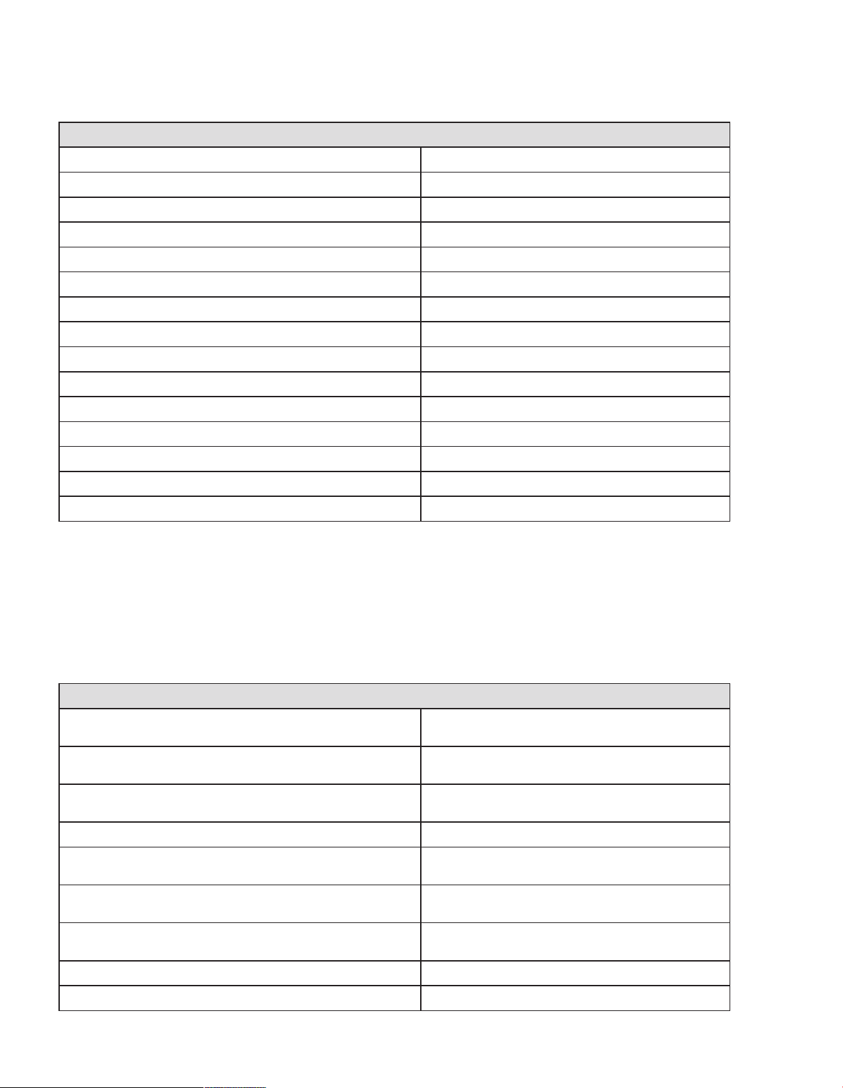
4.1.1 System Performance
Frequency Response (-3dB) *
Frequency Response (-10dB) * 45Hz - 18kHz
Recommended High-Pass 48 Hz - w/ minimum 24 dB / Butterworth Filter
Horizontal Nominal Dispersion (-6dB) 160°
Vertical Nominal Dispersion (-6dB) 20°
Recommended Crossover Frequency 420Hz (acoustic, active, external DSP)
Low-Frequency Drivers Dual 10” w 2.5” Voice Coil
Mid/High-Frequency Drivers Coaxial: 4” mid driver, 2.55” hf tweeter
Long Term Power Handling (Low Freq.) ** 600 W (2400 W peak)
Long Term Power Handling (High Freq.) ** 110 W (440 W peak)
Bi-Amp Impedance (Low Freq.) 4 ohms
52Hz - 18kHz
Bi-Amp Impedance (High Freq.)
Pressure Sensitivity @ 1W/1m (Low Freq.) *** 101 dB
Pressure Sensitivity @ 1W/1m (High Freq.) *** 111.4 dB
Bi-Amp Max SPL @ 1W/1m 131 dB SPL (140 dB SPL peak)
NOTES:
* Frequency response and range measured on-axis with recommended active EQ in an anechoic environment.
** Power handling tested using pink noise ltered to meet IEC 268-5,
6 dB crest factor, 100 hours (approx 4 days), with recommended active EQ.
*** Sensitivity measured in free eld (no boundary-loading gain) with recommended active EQ, referenced to 1W/1m. Maximum SPL calculated
from sensitivity and power handling specications, exclusive of power compression (100Hz-10KHz).
8 ohms
4.1.2 Physical Characteristics
Enclosure Material
Finish
Grille Material
Environmental Indoor use only.
Connectors/Bi-Amp
Suspension/Mounting
Dimensions (HxWxD)
Net Weight 83lbs / 37.65kg
Baltic birch plywood, engineered plastics, and
aluminum frame.
Two-part spray catalyzed Polyurea coating on
plywood.
14-gauge (2mm) perforated steel, powder-coated
nish, black.
Two (2) parallel-wired NL4 Neutrik® Speakon®
connectors.
Install side rigging, optional array frame
accessories.
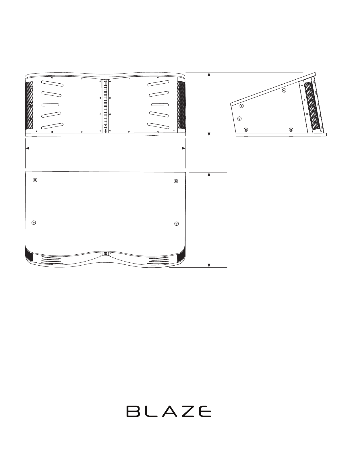
13.23” x 32.33” x 18.25”
(336.14 x 821.21 x 463.68mm)
Shipping Weight 88lbs / 39.91kg
Page 14
4. Technical Information
4.2 CCA10i-BA Mechanical Drawings
4.2.1 CCA10i-BA Loudspeaker Dimensions
32.33”
821.21mm
13.23”
336.14mm
NOTE: Rigging Plates add 0.24” (6.0mm)
to total CCA10i-BA loudspeaker width.
18.25”
463.68mm
Designed in USA/Denmark - Made in USA.
Blaze, 1904 Fairfax Road, Suite B, Greensboro, NC 27407, US. [email protected]. www.blaze-audio.com
Rev E/07/2023
 Loading...