

Page 1
Installation Instructions
Pedestal Models
FS 500 LE
FS 800 LE
Insert Models
IS 500 LE
IS 800 LE
Pecan Engineering Pty Ltd
13 Acorn Road
Dry Creek
South Australia 5094
Email info@pecan-eng.com.au
Phone: (08) 8349 8332
Fax: (08) 8260 6643
Page 2
Most building regulatory Authorities in Australia require any
wood heater installation to comply with Installation Standard
AS/NZS 2918:2001. Different states and councils may have
varying regulations. Check local building regulations before
installing the appliance.
All Blaze wood heaters have been tested to ensure that they
will meet the appropriate safety Standard requirements if the
instructions in this manual are followed. As the safety and
emissions performance can be affected by altering the
appliance, no modifications are allowed without written
permission from the manufacturer.
WE RECOMMEND THAT THE INSTALLATION OF YOUR BLAZE
WOOD HEATER BE CARRIED OUT BY A QUALIFIED
INSTALLER.
WARNING: THE APPLIANCE AND FLUE SYSTEM SHALL BE
INSTALLED IN ACCORDANCE WITH AS/NZS 2918:2001 AND
THE APPROPRIATE REQUIREMENTS OF THE RELEVANT
BUILDING CODE OR CODES.
WARNING: APPLIANCES INSTALLED IN ACCORDANCE WITH
THIS STANDARD SHALL COMPLY WITH THE REQUIREMENTS
OF AS/NZS 4012 & AS/NZS 4013 WHERE REQUIRED BY THE
REGUALTORY AUTHORITY, I.E. THE APPLIANCE SHALL BE
IDENTIFIABLE BY A COMPLIANCE PLATE WITH THE MARKING
‘TESTED TO AS/NZS 4012 & AS/NZS 4013’.
ANY MODIFICATION OF THE APPLIANCE THAT HAS NOT
BEEN APPROVED IN WRITING BY THE TESTING AUTHORITY
IS CONSIDERED TO BE IN BREACH OF THE APPROVAL
GRANTED FOR COMPLIANCE WITH AS/NZS 4012 & AS/NZS
4013.
CAUTION: MIXING OF APPLIANCE OR FLUE-SYSTEM
COMPONENTS FROM DIFFERENT SOURCES OR MODIFYING
THE DIMENSIONAL SPECIFICATION OF COMPONENTS MAY
RESULT IN HAZARDOUS CONDITIONS. WHERE SUCH ACTION
IS CONSIDERED, THE MANUFACTURER SHOULD BE
CONSULTED IN THE FIRST INSTANCE.
CAUTION: CRACKED AND BROKEN COMPONENTS, EG. GLASS
PANELS OR CERAMIC TILES, MAY RENDER THE INSTALLATION
UNSAFE.
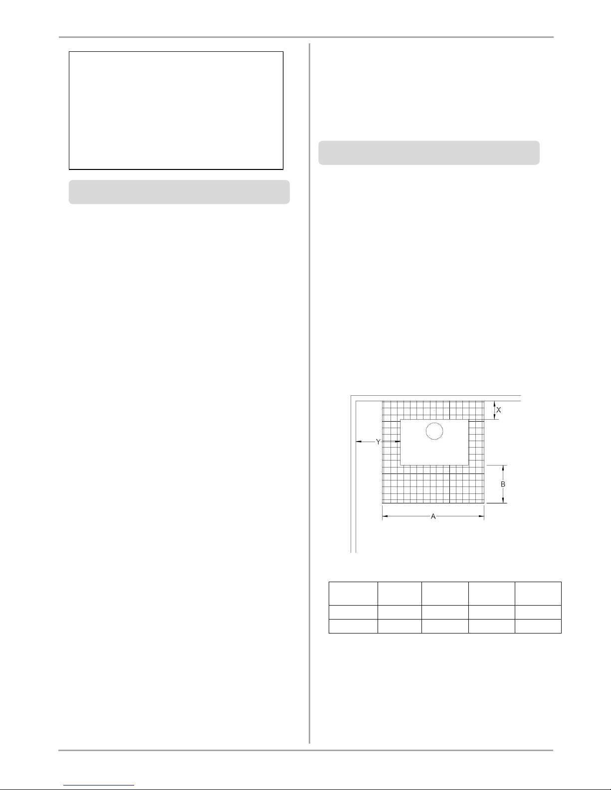
2.1 Positioning the Heater
First review the necessary clearances specified below before
considering where to position the heater.
Also check the practicability of installing the flue system in
relation to any obstructing roof beams before positioning
the heater.
These clearance distances can only be reduced if the
surrounding walls are made of non-combustible material,
eg. Stone, brick, or concrete. If non-combustible material,
distance can be reduced to 100 mm. Alternatively, shielding
of the wall(s) can reduce clearances (refer to next section
for more detail).
2.1.1 Standard Installation:
Model
Rear (X)
Side (Y)
Hearth
width (A)
Hearth
depth (B)
FS 500 LE
125
350
900
300
FS 800LE
175
425
1000
400
(Measurements are in millimetres – mm)
THE INSTALLATION INSTRUCTIONS IN THIS
MANUAL APPLY TO THE BLAZE FS 500 LE &
FS 800 LE FREE-STANDING, AND IS 500 LE &
IS 800 LE INSERTT WOOD HEATER MODELS.
THEY HAVE BEEN TESTED FOR EMISSIONS AND
EFFICIENCY AND COMPLIES ACCORDING TO
AS/NZS 4012:1999 & AS/NZS 4013:1999.
1. INTRODUCTION
2. INSTALLING PEDESTAL (FS) MODELS
Page 3
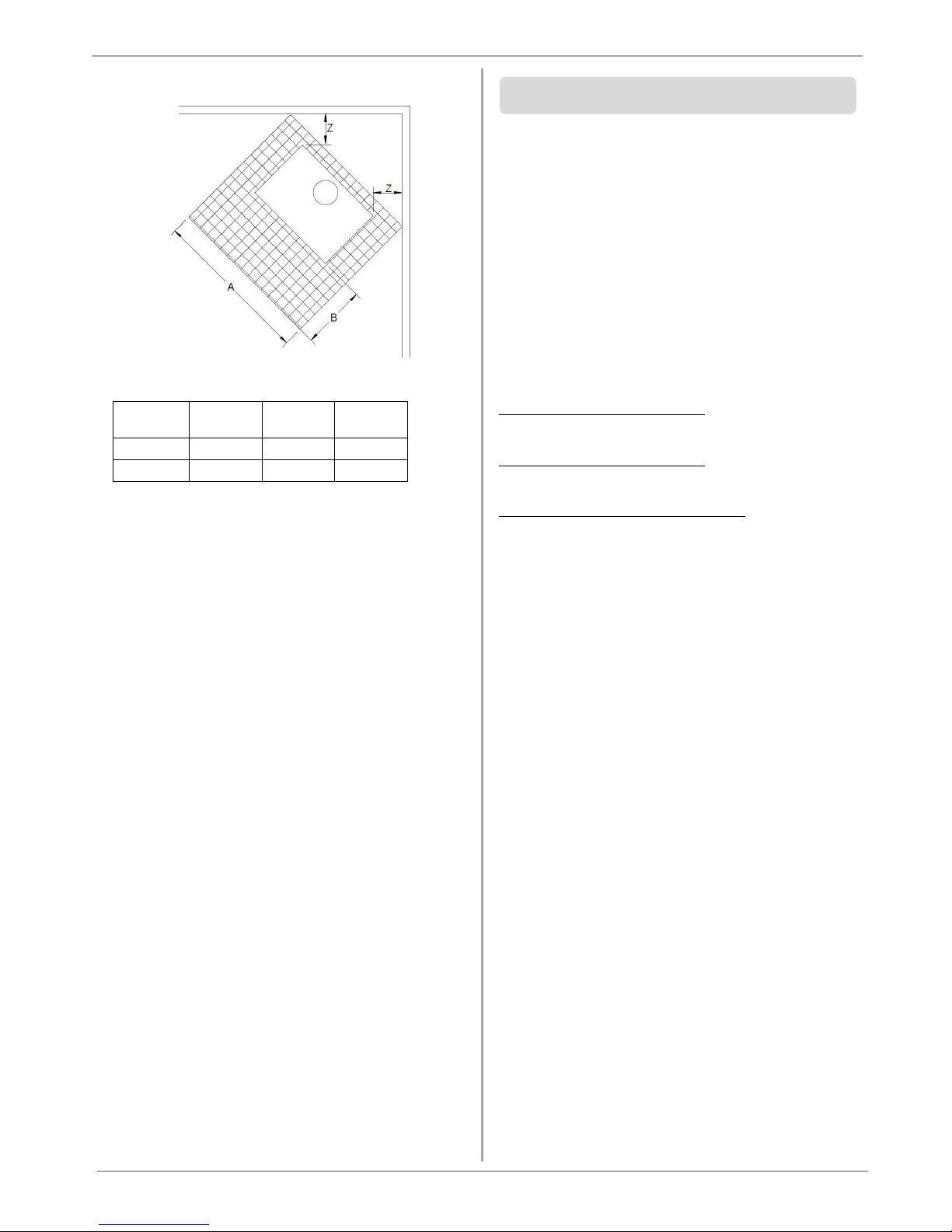
2.1.2 Corner Installation:
Model
Side (Z)
Hearth
width (A)
Hearth
depth (B)
FS 500 LE
100
900
300
FS 800LE
150
1000
400
(Measurements are in millimetres – mm)
2.2 Floor Protector (Hearth)
Unless the FS heater will be standing on a heat resistant floor
such as concrete slab with slate or tiles, it will be necessary to
provide a floor protector (hearth).
The dimensions given in above (Section 2.1) are the minimum
required for the floor protector. It may be desirable, for
example aesthetic reasons, for the floor protector to be
larger than these minimum dimensions.
The floor protector shall be constructed of 15mm minimum
thick fibre cement sheet with thermal conductivity not
greater than 0.33W/m ºK. The floor protector may be laid
directly on the combustible floor.
For more details and variations on floor protectors refer to
AS/NZS 2918:2001 Clause 2.2, 3.3.1, & 3.3.2.
If it is necessary to install a heater closer to a combustible
surface than the stated requirements in Section 2 of this
Installation Guide, it must be done in accordance with
Australian Standard AS/NZS 2918:2001 Section 3, Tables 3.1
& 3.2.
Shield Construction :- The shield shall be constructed from a
heat resistant material. The shield must be fixed to the
surface that requires protection and NOT the heater.
The Standard allows three options to reduce stated
clearances.
Single layer of continuous material with Minimum Air Gap of
12mm—Clearance Factor = 0.40
Single layer of continuous material with Minimum Air Gap of
25mm—Clearance Factor = 0.30
Two spaced layers of continuous material with Minimum Air
Gap of 12mm + 12mm—Clearance Factor = 0.20
The shielding must be open at the top and bottom (vented)
to allow a continuous air flow. It is this air flow that keeps
the surface requiring protection cool. Fixings should not
impede this air flow.
The shielding needs to go far enough along and up the wall
so that the original side and rear required clearances are not
compromised. As the flue is now closer to the wall the
shielding should also protect the wall from the flue pipe.
For example:
Side wall clearance for the FS 800 LE is 425mm.
A 12mm gapped shield on the wall with a factor of 0.40.
Calculate:- 425mm x 0.40 = 170mm. This is the new side wall
minimum clearance.
The shielding needs to be large enough so that none of the
original clearances of 425mm are compromised.
3. Reducing Clearances to Combustible Walls
Page 4

The flue system used when installing the heater MUST
comply with the current installation standard AS/NZS 2918.
Full instructions on the installation of the flue will be supplied
with the flue kit. These MUST be followed closely, including
the minimum exit height from the top of the floor protector
being not less than 4.6m, and the minimum exit height above
the roof line of roof ridge as detailed in the instructions.
The flue must be fitted with a full length, half radius
perforated decro mesh flue shield extending from the heater
through into the drop box penetrating the ceiling.
Stainless Steel Flue Heat Reflector
The heater is supplied with a 525mm long stainless steel heat
reflector. This must be installed inside the decro mesh casing
and positioned behind the flue immediately above the heater.
Flue Spigot Heat Reflector
A flue spigot heat reflector is also supplied inside the heater.
This must be fitted to the flue spigot on the heater. The three
lugs on the reflector hang inside the flue ring (spigot) with
the reflector orientated at the rear of the heater.
This device reflects the heat radiating from the flue spigot on
to the rear wall.
If the draft is insufficient or periodic down drafting occurs
and the heater smokes or only burns slowly, extending the
flue or fitting a specialist cowl will usually resolve the issue.
4. INSTALLING THE FLUE
Page 5

The dimensions given below for the Blaze IS 500 LE and IS
800 LE models represent the minimum clearance to
combustible materials, i.e. mantle-piece, when installed in a
non-combustible fireplace.
For variations to clearances relative to a combustible mantle-
piece refer to AS/NZS 2918 Clause 3.4.2.
MODEL X (Height to
Mantel-piece)
Y
(Width
between
columns)
A
(Hearth
Width)
B
(Hearth
Depth)
IS 500 LE
1100
(500 above air
vent)
900
900
450
IS 800 LE
1500
(850 above air
vent)
1080
1000
600
(Measurements are in millimetres – mm)
Floor Protector (Hearth)
The dimensions given in the table above are the minimum
required for the floor protector. It may be desirable, for
example aesthetic reasons, for the floor protector to be
larger than these minimum dimensions.
The floor protector shall be constructed of 22.5mm minimum
thick fibre cement sheet with thermal conductivity not
greater than 0.33W/m ºK. The floor protector may be laid
directly on the combustible floor.
For more details and variations on floor protectors refer to
AS/NZS 2918:2001 Clause 2.2, 3.3.1, & 3.3.2.
The baffle plate should be installed before installing the
fire bricks.
Place the baffle inside the firebox with the larger of the
folds at the front and directed upwards (refer to
diagram below for correct orientation).
Raise the front of the baffle, tilting it back and raise so
that it clears and rests on the front support rods.
Raise the rear of the baffle, bringing it forward enough
to clear the rear support rods.
Once clear of the rear support rods, push the baffle back
so that it is resting hard up against the rear of the
firebox.
5. INSTALLING INSERT (IS) MODELS
6. INSTALLING BAFFLE PLATE
Page 6

FS 500 LE & IS 500 LE – Brick Layout
1) Place two full size (235 x 175 x 25) and one (235 x 140 x
25) along the back
2) Place once full size and one half size (235 x 85 x 25) along
each side
3) Place two full size and one half size in the base
4) Place the two corner retainers on the corners to hold the
bricks upright
5) Place a straight flat retainer over each of the other joins
along the rear and sides
FS 800 LE & IS 800 LE – Brick Layout
1) Place three full size (285 x 175 x 25) along the back
2) Place two full size along each side
3) Place three full size in the base
4) Place the two corner retainers on the corners to hold the
bricks upright
5) Place a straight flat retainer over each of the other joins
along the rear and sides
Model – FS 500 LE
Model – FS 800 LE
8. TECHNICAL DRAWINGS
7. INSTALLING FIRE BRICKS
Page 7

Model – IS 500 LE
Model – IS 800 LE
 Loading...