

Blaupunkt 40/148Z-GB-5B2-FGKU, 50/148Z-GB-5B2-FGKU User Manual

Full HD LED TV with Freeview HD & USB Media Player
User Guide
Model No
40/148Z-GB-5B2-FGKU
50/148Z-GB-5B2-FGKU

5
IMPORTANT SAFETY INSTRUCTIONS
Please read these instructions. All the safety and operating instructions should be read before the
appliance is operated.
Important Information Regarding Use of
Video Games, Computers, Captions or Other
Fixed Image Displays
The extended use of fi xed image program material
can cause a permanent “shadow image” on the
LCD/LED panel.
This background image is viewable on normal
programs in the form of a stationary fi xed
image. This type of irreversible LCD/LED panel
deterioration can be limited by observing the
following steps:
1. Reduce the brightness/contrast setting to a
minimum viewing level.
2. Do not display the fi xed image for extended
periods of time.
3. Turn the power off when not in actual use.
Examples of images that you need to watch out
for are as follows (this is not an exhaustive list):
• TV Channel Logos: e.g. Shopping channel logos
and pricing displays-especially if they are
bright and stationary. Moving or low-contrast
graphics are less likely to cause ageing of the
screen.
• Time Displays
• Teletext: Do not view a stationary page for a
long period of time
• TV/DVD Menus: e.g. Listings of DVD disc content
• Pause Mode: Do not leave the TV in pause mode
for long periods of time, e.g. When watching
DVDs or videos.
How do I dispose of this product?
UK: Waste electrical products should not be
disposed of with household waste. Separate
disposal facilities exist. For your nearest facilities,
please see www.recycle-more.co.uk or in store for
details.
ROI: Waste electrical products should not be
disposed of with household waste. Separate
disposal facilities exist. Check with your Local
Authority or retailer for recycling advice.
Batteries
• Do not expose batteries to high
temperatures, excessive heat,
prolonged sunshine or fi re
as this may cause leakage,
explosion or ignition.
• Observe the correct polarity when
inserting batteries.
• Do not use different types of
batteries together or mix old and
new batteries.
• Dispose of batteries in an
environmentally friendly way.
• Certain regions may regulate the
disposal of batteries.
Please consult your local authority.
Cd
Important - Once ‘shadow image/screen burn’
occurs, it will never disappear and is not repairable
under warranty.
5

7
CONTENTS
Manufacturers Guarantee Information . . . . . . . . . . . . . . . . . . . . . . . . . . . . . . . . . . . . . . 3
Important Safety Instructions . . . . . . . . . . . . . . . . . . . . . . . . . . . . . . . . . . . . . . . . . . . . . . 4-5
What is Included in the Box . . . . . . . . . . . . . . . . . . . . . . . . . . . . . . . . . . . . . . . . . . . . . . . 8
Attaching the Stand . . . . . . . . . . . . . . . . . . . . . . . . . . . . . . . . . . . . . . . . . . . . . . . . . . . . . 9-10
Detaching the Stand/ Securing the TV to a Wall . . . . . . . . . . . . . . . . . . . . . . . . . . . . . . . 11
Wall Mounting . . . . . . . . . . . . . . . . . . . . . . . . . . . . . . . . . . . . . . . . . . . . . . . . . . . . . . . . . 12
Remote Control . . . . . . . . . . . . . . . . . . . . . . . . . . . . . . . . . . . . . . . . . . . . . . . . . . . . . . . . . 13
Connections . . . . . . . . . . . . . . . . . . . . . . . . . . . . . . . . . . . . . . . . . . . . . . . . . . . . . . . . . . . . 16-19
TV Menu Operation . . . . . . . . . . . . . . . . . . . . . . . . . . . . . . . . . . . . . . . . . . . . . . . . . . . . . 21-27
Channel Menu . . . . . . . . . . . . . . . . . . . . . . . . . . . . . . . . . . . . . . . . . . . . . . . . 21
Picture Menu . . . . . . . . . . . . . . . . . . . . . . . . . . . . . . . . . . . . . . . . . . . . . . . . . 22-23
Sound Menu . . . . . . . . . . . . . . . . . . . . . . . . . . . . . . . . . . . . . . . . . . . . . . . . . . 24
Time Menu . . . . . . . . . . . . . . . . . . . . . . . . . . . . . . . . . . . . . . . . . . . . . . . . . . . 25
Setup Menu . . . . . . . . . . . . . . . . . . . . . . . . . . . . . . . . . . . . . . . . . . . . . . . . . . 26
Lock Menu . . . . . . . . . . . . . . . . . . . . . . . . . . . . . . . . . . . . . . . . . . . . . . . . . . . 27
TV Buttons and Input Source Menu . . . . . . . . . . . . . . . . . . . . . . . . . . . . . . . . . . . . . . . . . 15
Network Confi guration . . . . . . . . . . . . . . . . . . . . . . . . . . . . . . . . . . . . . . . . . . . . . . . . . . 28
7 Day TV Guide and Channel List . . . . . . . . . . . . . . . . . . . . . . . . . . . . . . . . . . . . . . . . . . . 29
USB Mode / Media Player . . . . . . . . . . . . . . . . . . . . . . . . . . . . . . . . . . . . . . . . . . . . . . . . . 30
General Information . . . . . . . . . . . . . . . . . . . . . . . . . . . . . . . . . . . . . . . . . . . . . . . . . . . . . 31-34
Using your TV with a Sky digital set top box . . . . . . . . . . . . . . . . . . . . . . . . 31
Frequently Asked Questions . . . . . . . . . . . . . . . . . . . . . . . . . . . . . . . . . . . . . 32
Technical Specifi cations . . . . . . . . . . . . . . . . . . . . . . . . . . . . . . . . . . . . . . . . . 33-34
7
What is Included in the Box
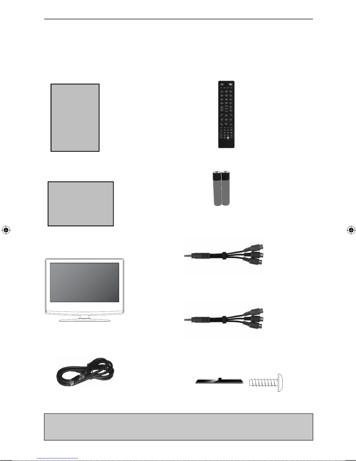
WHAT IS INCLUDED IN THE BOX
Accessories
Included with this TV are the following accessories
1 x User Guide
User Guide
1 x Quick Start Guide
Quick Start
Guide
1 x Remote Control
2 x AAA Batteries
1 x Mini Component / YPbPr
1 x TV
1 x RF Cable
1 x Mini AV / Composite cable
1 x Stand plus screws
Please save your box/packaging as you will need this in the event of warranty/service repair or support.
We are unable to carry out warranty/service if you are unable to package it correctly. The safest way to
package your item in the event of warranty/service repair is in it’s original box/packaging.
8
9
Attaching the Stand
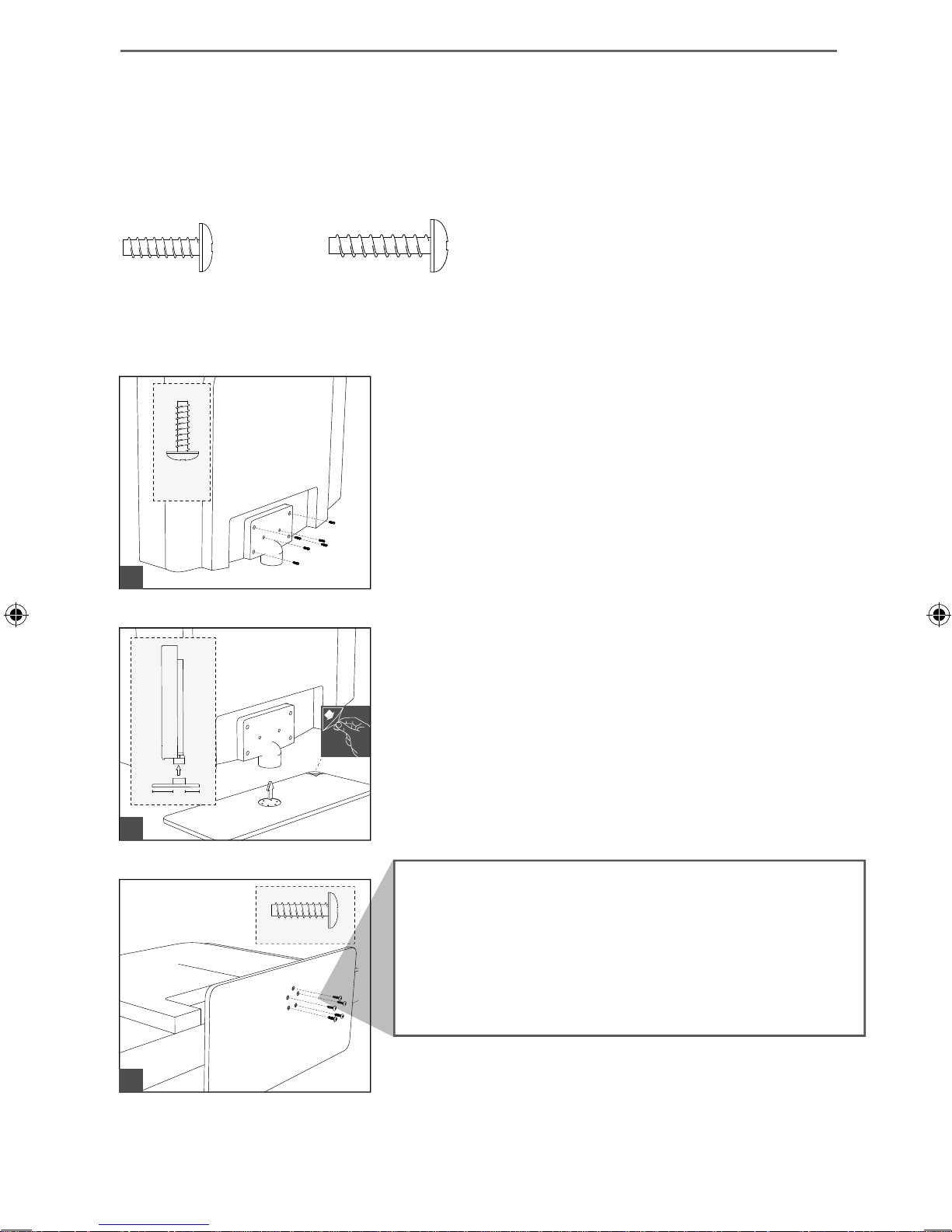
ATTACHING THE STAND
Attaching the stand 40” models only
To complete the stand installation you will require a cross head screw driver
There are two types of screws provided as shown below.
5 x ST (3.7x18)6 x ST (4x14)
Used for attaching the stand neck
to the TV ( g.1)
6 x
ST (4x14)
Used for attaching the stand base
to the stand neck ( g.3)
(fi g.1) Attach the stand neck to the rear of the TV set
1
1 1/2
using the 6 x ST(4x14) screws provided.
(fi g.2) Peel off the protective plastic cover then attach
2
5 x ST(3.7x18)
the stand base to the stand neck.
When securing the self-tapping screw/s into the base of the stand (on
fi rst installation) the screw/s will be naturally tight as they create a
thread in the plastic of the stand neck in order to support a TV of this size.
a) Ensure the cross head screw driver tip fi ts correctly into the head of the
screw and that it is not too big or small.
b) Screw in all screws individually and partially before tightening all of the
screws fully.
c) If they become very tight try loosening them slightly and then re-tightening
them once again as this will continue the process of creating the thread for
the screws.
3
(fi g.3) Secure the base to the neck by using the
5 x ST (3.7x18) screws provided.
9

ATTACHING THE STAND
Attaching the stand for 50” models only
To complete the stand installation you will require a cross head screw driver
There are two types of screws provided as shown below.
5 x ST (3.7x20)7 x M (4x16)
Used for attaching the stand neck
to the TV ( g.1)
7 x
M (4x16)
Used for attaching the stand base
to the stand neck ( g.3)
Attaching the Stand
1
2
11/2
5 x ST 3.7x20
(fi g.1) Attach the stand neck to the rear of the TV set
using the 7 x M(4x16) screws provided.
(fi g.2) Peel off the protective plastic cover then attach
the stand base to the stand neck.
When securing the self-tapping screw/s into the base of the stand (on
fi rst installation) the screw/s will be naturally tight as they create a
thread in the plastic of the stand neck in order to support a TV of this size.
a) Ensure the cross head screw driver tip fi ts correctly into the head of the
screw and that it is not too big or small.
b) Screw in all screws individually and partially before tightening all of the
screws fully.
c) If they become very tight try loosening them slightly and then re-tightening
them once again as this will continue the process of creating the thread for
the screws.
3
10
(fi g.3) Secure the base to the neck by using the
5 x ST (3.7x20) screws provided.
11
Detaching the Stand/Securing the TV to a Wall
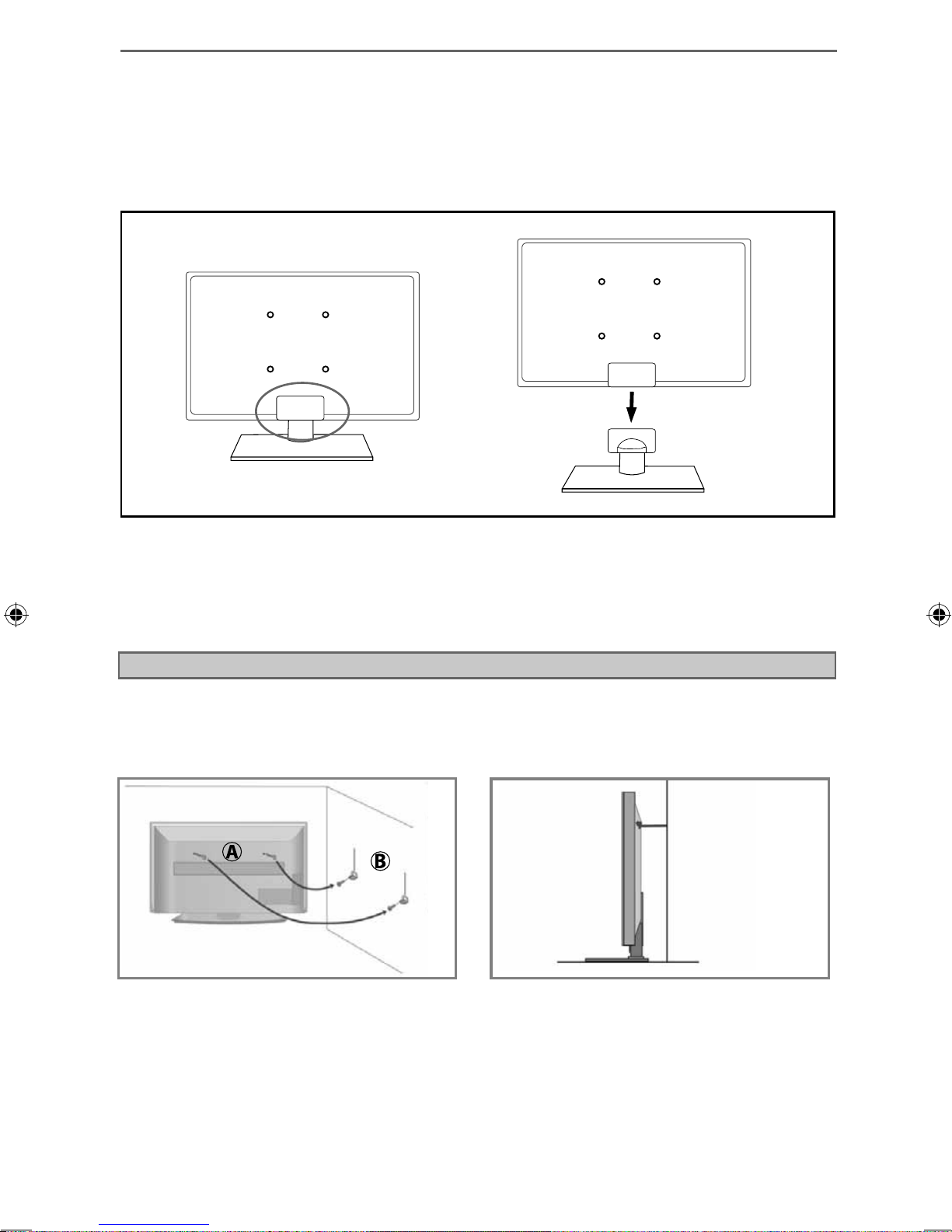
DETACHING THE STAND
Detaching the stand
Remove the screws highlighted then remove the stand base and neck from the rear of the TV set.
Securing the TV to a Wall
For maximum security in the home when using a TV with its stand anti-tip straps should be fi tted. These
are available from supermarket websites and other websites and are an easy, inexpensive and effective
way of ensuring your TV stays safely upright. Straps are designed to be attached to the rear of the TV and
then tethered to the wall or the furniture the TV is stood on.
Note - Please ensure that children do not climb on the TV set.
A) Using one or both of the top wall-mounting
holes and screws (the screws are already supplied
in the wall mounting holes) fasten one end of the
fastening cord/s to the TV.
The Royal Society for the Prevention of Accidents is urging people to take care with fl at-screen televisions.
RoSPA stated in 2010 that “Toddlers are particularly at risk of pulling fl at-screen televisions on to
themselves. They are unsteady on their feet and are attracted by colourful television images.”
The risk is increased as televisions become lighter.
B) Secure the other end of the fastening cord/s to
your wall. (you will need screws/fi xings suitable
for your wall type - available separately from most
DIY stores).
11
Wall Mounting
WALL MOUNTING
Wall mounting the TV
IMPORTANT - Before drilling any holes in the wall ensure you are not drilling
where there could be any electrical wires, water or gas pipes.
1) Remove the four screws highlighted that are supplied in the wall
mounting holes.
2) The wall mount can now be easily attached to the mounting holes
on the rear of the TV.
For VESA wall mounting information please refer to the Technical
Specifi cation page.
Important – If wall mounting this TV, only use the screws already provided in the wall mounting holes.
Using other screws which are longer could cause irreparable damage to internal parts.
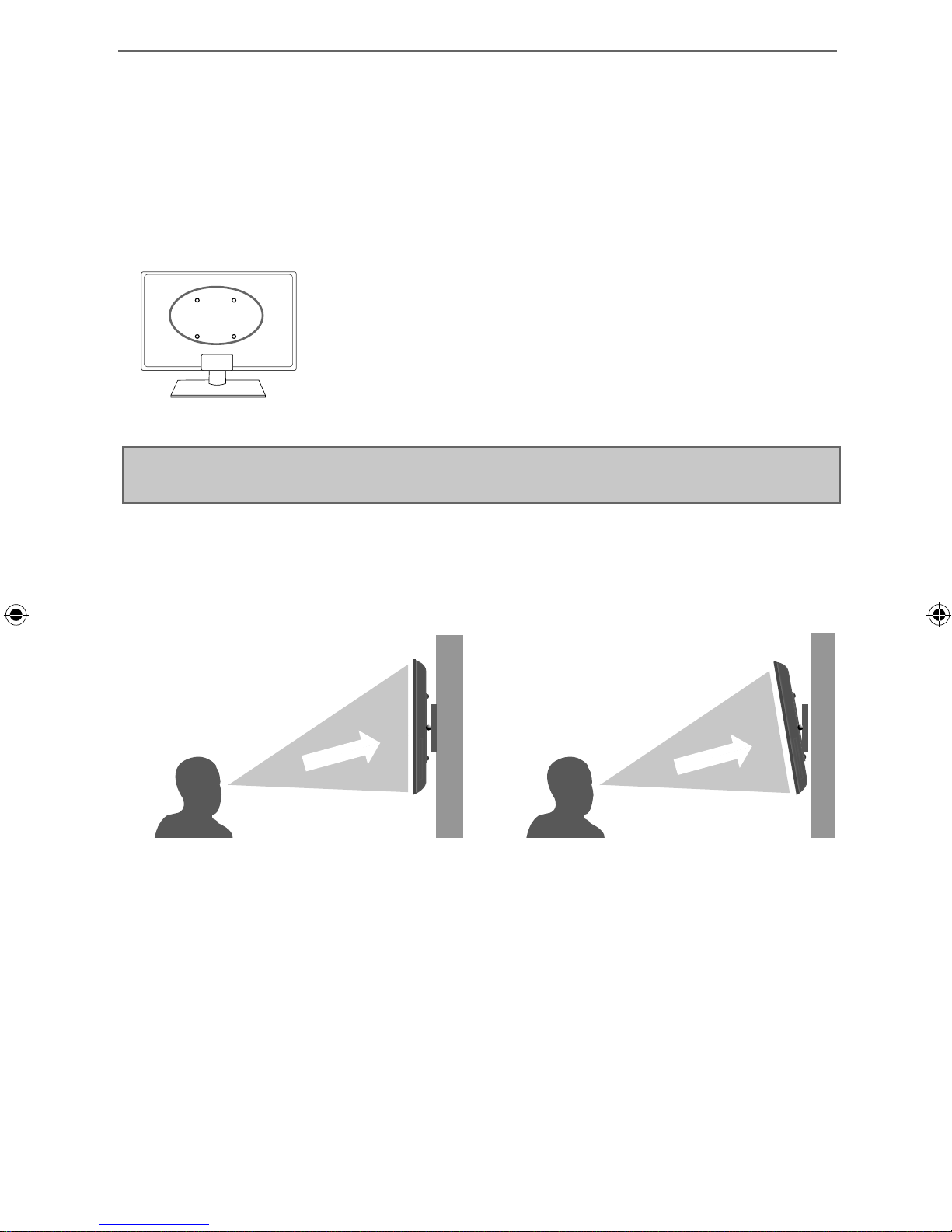
For optimum viewing, if wall mounting the TV higher than eye level, the TV should be tilted downwards
so that the TV’s screen is ‘face on’. See fi g 1 and 2.
fi g 1 fi g 2
INCORRECT
TV
Viewing angle
CORRECT
TV
Viewing angle
12
 Loading...