

BLAUBERG Ventilatoren Komfort ERV EC DB 150 S14, Komfort ERV EC DB 250 S14, Komfort ERV EC DB 350 S14 Operation Manual
Page 1

OPERATION MANUAL
Komfort ERV EC DB 150 S14
Komfort ERV EC DB 250 S14
Komfort ERV EC DB 350 S14
AIR HANDLING UNIT WITH HEAT
AND HUMIDITY RECOVERY
EN
Page 2
2
www.blaubergventilatoren.de
Komfort ERV EC DB S14
Safety requirements ........................................................................................................................................ 2
Purpose ..................................................................................................................................................................... 4
Delivery set ............................................................................................................................................................. 4
Designation key ................................................................................................................................................... 4
Technical data ....................................................................................................................................................... 5
Design and operating logic .......................................................................................................................... 7
Mounting and set-up ....................................................................................................................................... 9
Connection to power mains ........................................................................................................................ 11
Unit control ............................................................................................................................................................. 12
Maintenance .......................................................................................................................................................... 14
Troubleshooting .................................................................................................................................................. 15
Storage and transportation regulations .............................................................................................. 15
Manufacturer's warranty ................................................................................................................................ 16
Acceptance certificate ..................................................................................................................................... 17
Seller information ............................................................................................................................................... 17
Installation certificate ....................................................................................................................................... 17
Warranty card ........................................................................................................................................................ 17
The user’s manual consisting of the technical details, operating instructions and technical specification applies to the installation and mounting of
the air handling unit with heat and humidity recovery Komfort ERV EC DB... S14, (hereinafter „the unit“ as mentioned in the „Safety Requirements“
and „Manufacturer’s Warranty“ sections as well as in warnings and information blocks).
Read the user’s manual carefully prior to installing and operating the unit.
Fulfil the user’s manual requirements as well as the provisions of all the applicable local and national construction, electrical and technical norms and
standards.
The warnings contained in the user’s manual must be considered most seriously since they contain vital personal safety information.
Failure to follow the rules and safety precautions noted in this user’s manual may result in an injury or unit damage.
After a careful reading of the manual, keep it for the entire service life of the unit.
While transferring the unit control the User’s manual must be turned over to the receiving operator.
Symbol legend:
WARNING!
DO NOT!
SAFETY REQUIREMENTS
CONTENT
Page 3

www.blaubergventilatoren.de
3
Komfort ERV EC DB S14
UNIT MOUNTING AND OPERATION SAFETY PRECAUTIONS
• Disconnect the unit from power mains prior to
any installation operations.
• Unpack the unit with care.
• Do not lay the power cable of the unit in close
proximity to heating equipment.
• While installing the unit follow the safety
regulations specific to the use of electric tools.
• Do not use damaged equipment or cables
when connecting the unit to power mains.
• Do not operate the unit outside the
temperature range stated in the user's manual.
• Do not operate the unit in aggressive or
explosive environments.
• Do not touch the unit controls with wet hands.
• Do not carry out the installation and
maintenance operations with wet hands.
• Do not wash the unit with water.
• Protect the electric parts of the unit against
ingress of water.
• Do not allow children to operate the unit.
• Disconnect the unit from power mains prior to
any technical maintenance.
• Do not store any explosive or highly flammable
substances in close proximity to the unit.
• When the unit generates unusual sounds, odour
or emits smoke disconnect it from power supply
and contact the Seller.
• Do not open the unit during operation.
• Do not direct the air flow produced by the unit
towards open flame or ignition sources.
• Do not block the air duct when the unit is
switched on.
• In case of continuous operation of the unit
periodically check the security of mounting.
• Do not sit on the unit and avoid placing foreign
objects on it.
• Use the unit only for its intended purpose.
THE PRODUCT MUST BE COLLECTED SEPARATELY AT THE END OF SERVICE LIFE.
DO NOT DISPOSE OF AS UNSORTED MUNICIPAL WASTE.
Page 4

4
www.blaubergventilatoren.de
Komfort ERV EC DB S14
The unit is an energy saving unit based on heat recovery technology and is one of the energy saving components used in the buildings and premises.
The unit is a component part and is not designed for stand-alone operation.
The unit is designed to provide permanent controlled air exchange by means of mechanical ventilation in houses, offices, hotels, cafés, meeting halls
and other mechanically ventilated premises as well as utilization of extract air heat energy to warm up supply purified air.
THE UNIT MAY NOT BE OPERATED BY CHILDREN OR PERSONS WITH REDUCED PHYSICAL,
MENTAL OR SENSORY CAPACITIES, OR LACKING THE APPROPRIATE TRAINING.
THE UNIT MUST BE INSTALLED AND CONNECTED ONLY BY PROPERLY QUALIFIED PERSONNEL
AFTER THE APPROPRIATE BRIEFING.
THE CHOICE OF UNIT INSTALLATION PLACE MUST PREVENT UNAUTHORIZED ACCESS BY
UNATTENDED CHILDREN.
Transported air must not contain any flammable or explosive mixtures, evaporation of chemicals, sticky substances, fibrous materials, coarse dust, soot
and oil particles or environments favourable for the formation of hazardous substances (toxic substances, dust, pathogenic germs).
Name Quantity
Ventilation air handling unit 1 item
User's manual 1 item
Control panel 1 item
Mounting box for wall surface mounting 1 item
Mounting box for wall flush mounting 1 item
Packing box 1 item
Komfort ERV EC DB X S14
Rated air capacity, m3/h
Control panel
Motor type
EC: electronically commutated
Unit series
Casing type
D: suspended mounting, horizontal spigots
Heat exchanger type
ERV: heat and humidity recovery
Bypass
PURPOSE
DELIVERY SET
DESIGNATION KEY
Page 5
www.blaubergventilatoren.de
5
Komfort ERV EC DB S14
The unit is rated for indoor application with the ambient temperature ranging from +1 ˚C up to +40 ˚C and relative humidity up to 80 %.
The unit is rated as a class I electric appliance.
Hazardous parts access and water ingress protection rating: IP44 for the unit motors and IP22 for the assembled unit connected to the air ducts.
The unit design is regularly improved, so some models may slightly differ from those ones described in this manual.
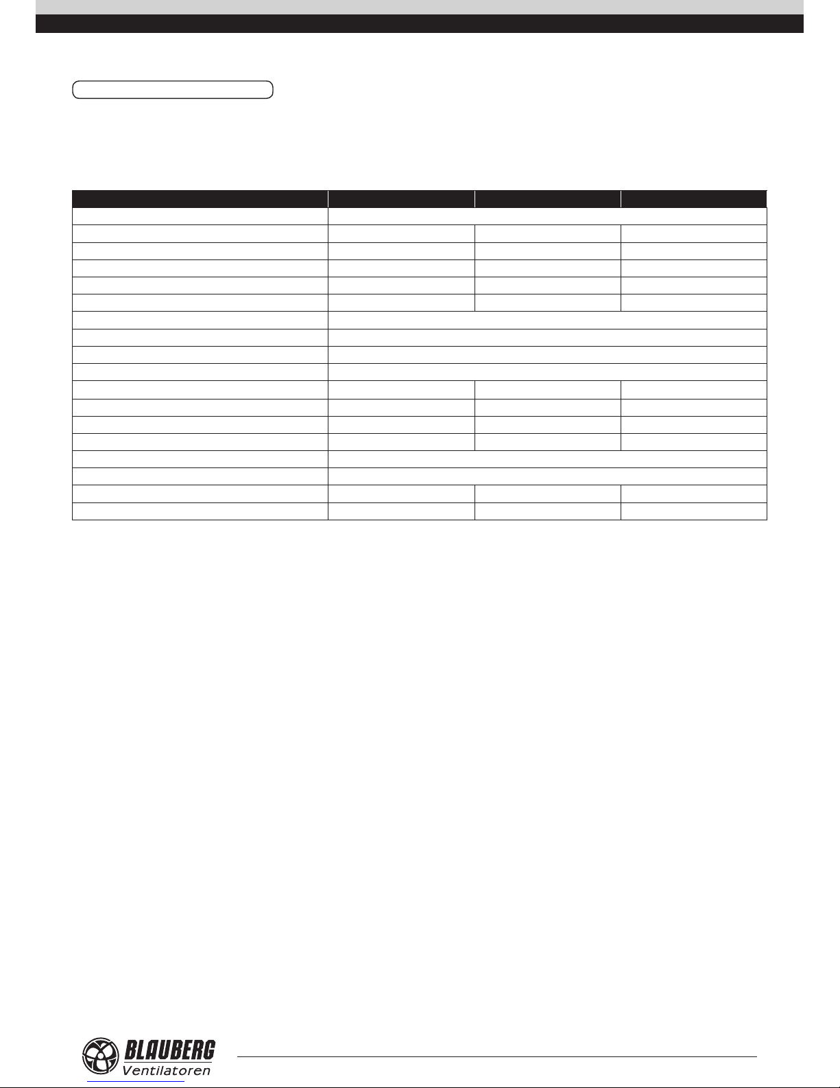
Technical data Komfort ERV EC DB 150 S14 Komfort ERV EC DB 250 S14 Komfort ERV EC DB 350 S14
Supply Voltage, 50–60 Hz [V] 1~ 230
Max. power consumption [W]
70
84 150
Max. current consumption [A] 0.6 0.7 1.0
Air capacity [m3/h] (CFM) 180 300 400
RPM [min-1] 1925 2000 3200
Noise level, 3 m [dB(A)] 32 36 46
Transported air temperature [˚C] from -25 up to +40
Casing material Painted steel
Insulation 5 mm, 10 mm foam rubber
Extract filter G4
Supply filter
G4 and F8 (PM2.5 93 %) G4 and F8 (PM2.5 83 %) G4 and F8 (PM2.5 87 %)
Connected air duct diameter [mm] Ø 100 Ø 150 Ø 150
Heat recovery efficiency [%] 68–82 63–7 3 68–85
Humidity recovery efficiency [%] 22–41 16 –27 19–3 4
Heat exchanger type Cross-flow
Heat exchanger material Polymerized cellulose
Weight [kg] 26 29 42
Energy efficiency class A B A
TECHNICAL DATA
Page 6
6
www.blaubergventilatoren.de
Komfort ERV EC DB S14
H1
H
A2
A1
A
B1
B2
ØD
B
L4
L2LL1
L3
L5
L2 L L1
L3
A B
A
B
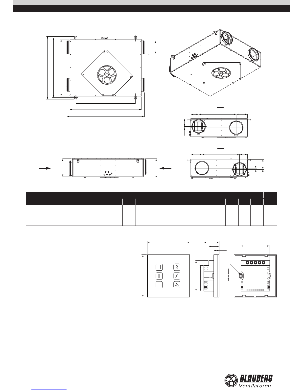
Model
Dimensions, mm
Ø D A A1 A2 B B1 B2 H H1 L L1 L2 L3 L4 L5
Komfort ERV EC DB 150 S14
99 947 854 676 704 743 793 227 247 480 92 128 25 113 113
Komfort ERV EC DB 250 S14
149 947 854 676 704 743 793 227 247 480 92 128 25 113 88
Komfort ERV EC DB 350 S14
149 1117 1024 846 754 793 843 277 297 488 109 153 50 88 138
R1,5
OUTOUT OUT IN
+RxTx
-
86
58
39
21
11,2
86
4
62,3
52
Control panel
The touch control buttons and the alarm indicator are located on
the sensor control panel.
Power supply voltage 8–30 V
Temperature range from 0 ˚C up to +45 ˚C
Service life 100 000 switching operations
Ingress Protection IP30
Weight 150 g
Humidity range from 5 % to 80 %
(no condensation)
Page 7

www.blaubergventilatoren.de
7
Komfort ERV EC DB S14
Control panel
Supply fan
Extract fan
*Bypass damper
Extract air lter
Control unit
Freeze protection temperature sensor
Electric lead-ins
Service side
Access door for maintenance
of the lters and heat exchangers
Cross-ow heat exchanger
Supply air lter
**Humidity sensor
The access door is located on the service side of the unit. It is fixed with hand screws and enables maintenance access for cleaning or replacement of
the filters and the heat exchanger.
The control unit is located in the unit casing.
The control cable and the grounding cable are connected to the control unit through the electric lead-ins on the unit side wall.
The plate enthalpy cross-flow heat exchanger is made of polymerized cellulose.
* The bypass damper is in open or closed position depending on the unit operation mode.
** Upon customer’s demand the unit may be equipped with a humidity sensor (available as an accessory).
The unit with the installed humidity sensor maintains a set indoor humidity point. As the humidity reaches the set point, the unit starts operating with
the maximum speed.
As the humidity level drops down below the set point, the unit reverts to the previous operation mode.
Installation and connection of the humidity sensor must be carried out on site by a service technician.
UNIT DESIGN AND OPERATING LOGIC
Page 8

8
www.blaubergventilatoren.de
Komfort ERV EC DB S14
UNIT OPERATION MODES
Heat recovery mode: warm extract air from the room flows into the unit and is cleaned in the extract filter. Then the air is moved through the heat
exchanger and is exhausted outside with the extract fan.
Cold fresh air from outside flows into the unit, where it is cleaned in the supply filter. Then the air flows through the heat exchanger and is moved to
the room with the supply fan.
Supply air is heated in the heat exchanger by means of the extract air heat energy transfer to cold intake air. The air flows are fully separated while
flowing through the heat exchanger. Heat recovery minimizes heat losses, which reduces the heating costs in the cold season.
The enthalpy heat exchangers enables both heat and air humidity recovery. In the summer season the enthalpy heat exchanger cools down and
dehumidifies supply air and in the cold season warms it up and humidifies. The moisture vapour condensate generated by humid-laden extract air is
absorbed by the heat exchanger plates. The humidity and heat energy are transferred to the supply air and the microbes and odours are separated.
EXTRACT AIR
SUPPLY AIR
INTAKE AIR
EXHAUST AIR
Defrosting mode: the defrosting mode is designed for heat exchanger freezing protection and is activated on feedback from the freeze protection
temperature sensor in the exhaust air duct. Activation of the defrosting mode starts when the exhaust air temperature drops down to +3 ˚C. When
the exhaust air temperature exceeds above this temperature point, the unit reverts to the previous operation mode. In the defrosting mode only the
exhaust fan is turned off, the supply fan operates normally.
EXTRACT AIR
SUPPLY AIR
INTAKE AIR
EXHAUST AIR
Summer cooling mode: a parts of the intake air bypasses the heat exchanger along the bypass air duct, the bypass damper is opened. The intake air
stream temperature remains constant. This operation mode is applicable for the unit modifications with a bypass damper.
EXTRACT AIR
SUPPLY AIR
INTAKE AIR
EXHAUST AIR
Page 9

www.blaubergventilatoren.de
9
Komfort ERV EC DB S14
THE UNIT MUST BE MOUNTED BY A QUALIFIED EXPERT ONLY, PROPERLY TRAINED AND
HAVING THE REQUIRED TOOLS AND MATERIALS.
HUMIDITY SENSOR MOUNTING
The humidity sensor is not included into delivery set and is available as a specially ordered accessory.
The humidity sensor must be installed prior to unit mounting. Mounting steps:
• Remove the fastening screws on the service panel and remove it.
• Insert the humidity sensor in the mount on the inner casing wall close to the extract spigot and connect the humidity sensor contact socket to
the respective contact socket on the control unit, refer to the External wiring diagram.
• Install the service panel back.
UNIT MOUNTING
The unit is designed for suspended ceiling mounting by means of the threaded rods, nuts and vibration absorbing rubber.
The fasteners are not included in the delivery set and are available as specially ordered accessories.
While selecting fastener type consider the mounting surface material and the ventilation unit weight. For details please refer to the technical data of
the unit.
The fasteners must be selected by a professional!
Prior to the installation check the unit casing for any left-over foreign objects such as plastic film or paper.
While mounting the unit make sure to provide sufficient service access to the unit for maintenance and repair operations.
Keep the minimum distance between the unit and the ceiling 20 mm.
To attain the best performance of the unit and to minimise turbulence-induced air pressure losses connect a straight air duct section on both sides of
the unit.
Minimum straight air duct length:
• equal to 1 air duct diameter on intake side.
• equal to 3 air duct diameters on outlet side.
If the air ducts are not connected or the connected air ducts are too short, protect the unit parts from ingress of foreign objects.
Cover the spigots with a protecting grille or other protecting device with mesh width not more than 12.5 mm to prevent uncontrollable access to the
fans.
MOUNTING AND SET-UP
Page 10

10
www.blaubergventilatoren.de
Komfort ERV EC DB S14
Washer
Nut
Threaded rod
Vibration
absorbing rubber
min 20 mm
CONTROL PANEL MOUNTING
MAKE SURE THAT THE CONTROL PANEL IS NOT DAMAGED. DO NOT USE A DAMAGED CONTROL
PANEL! DO NOT INSTALL THE CONTROL PANEL ON AN UNEVEN SURFACE! WHILE TIGHTENING
THE SCREWS, DO NOT APPLY EXCESSIVE FORCE TO PREVENT THE CONTROL PANEL CASING
DEFORMATION.
Wall flush mounting of the control panel:
1. Prepare a wall recess and route
the required wires and cables to
the control panel installation place.
Install the mounting box for wall
flush mounting. The mounting box is
included in the delivery set.
2. Use a screwdriver to
carefully undo the latches
on the backside of the
control panel and remove
the back cover.
3. Screw the back side of the casing to
the mounting box through the mounting
holes. The screws for connection of
the control panel to the mounting box
are included on the delivery set. Then
connect the cable to the control panel
in accordance with the external wiring
diagram.
4. Press the latches to fix the
control panel display.
Wall surface mounting of the control panel:
Page 11

www.blaubergventilatoren.de
11
Komfort ERV EC DB S14
1. Route the required wires and cables
to the control panel installation place.
Drill the fastening holes in the wall
and screw the mounting box. The
mounting box is included in the
delivery set. The fastening screw for
fixation to the wall are not included.
2. Use a screwdriver to
carefully undo the latches
on the backside of the
control panel and remove
the back cover.
3. Screw the back side of the casing to
the mounting box through the mounting
holes. The screws for connection of
the control panel to the mounting box
are included on the delivery set. Then
connect the cable to the control panel
in accordance with the external wiring
diagram.
4. Press the latches to fix the
control panel display.
DISCONNECT THE UNIT FROM POWER SUPPLY PRIOR TO ANY ELECTRIC INSTALLATION OPERATIONS.
INSTALLATION SHALL ONLY BE PERFORMED BY A PROFESSIONAL ELECTRICIAN QUALIFIED FOR
UNASSISTED OPERATIONS WITH ELECTRICAL INSTALLATIONS UP TO 1000 V AFTER CAREFUL STUDY
OF THE PRESENT USER’S MANUAL.
THE RATED ELECTRICAL PARAMETERS ARE STATED ON THE RATING PLATE. ANY TAMPERING WITH
THE INTERNAL CONNECTIONS IS PROHIBITED AND WILL VOID THE WARRANTY.
DO NOT LAY THE CABLE IN CLOSE PROXIMITY TO THE CONTROL PANEL
CABLE! DO NOT COIL THE CABLE FROM THE CONTROL PANEL IN LOOPS
WHILE LAYING IT.
The unit is rated for connection to single-phase ac 230 V/50/60 Hz power mains.
The cable connecting the control panel and the air handling unit must match the criteria: 4x0.25 mm2 type and 10 m length.
For electric installations use insulated durable heat-resistant wires (cables, conductors) with the minimum wire cross section 1 mm2. Connect the unit to
power supply using the pre-wired power cable with Euro Plug XP through the external automatic circuit breaker with magnetic trip integrated into the
fixed wiring system of the house. The trip current of the circuit breaker must be consistent with the unit consumption current, refer the technical data.
The external circuit breaker position must ensure unhampered access for emergency shutdown of the unit. The trip current of the circuit breaker must
be consistent with the unit consumption current, refer the technical data.
Route the cables to the control unit through the electric lead-ins in the unit.
For accessing the control unit unscrew the control panel and remove it.
CONNECTION TO POWER MAINS
Page 12

12
www.blaubergventilatoren.de
Komfort ERV EC DB S14
Connect the unit in compliance with the external wiring diagram to the terminal block X1 located in the control unit.
The unit has provision for connection of extra control devices.
Control devices are not included in the delivery set and are available as specially ordered accessories.
Extra connections to the unit are shown in dotted lines.
• Connection of the automatic fire extinguishing system contact PK.
While connecting the automatic fire extinguishing system contact remove the jumper between the 11 and 12 terminals.
The connection relies on a normally closed dry contact. In case of a signal from a the central fire-fighting board the contact opens the control
circuit and cuts off power supply to the unit.
• Connection of the external control device such as CO2 sensor (NO, C).
Connect the CO2 sensor to the terminals 16 and 17.
The connection relies on a normally open dry contact. As the contact is closed, the unit turns to the maximum speed.
• Connection of the humidity sensor HV2 (+U, 0–10V, GND).
Connect the HV2 humidity sensor (not included into delivery set, available as a special order) to the contact socket in accordance with the
external wiring diagram.
• Connection of the external air dampers (SM1 supply air damper, SM2 exhaust air damper).
The air dampers and the electric actuator are not included in the delivery set, available as specially ordered accessories.
For connection of the air dampers use an electric actuator of LF 230 BELIMO type rated for 230 V power voltage and on/off control logic.
Connect the damper electric actuators to the terminals 22 and 23.
External wiring diagram
PK automatic re extinguishing
system (while connecting
the contact remove the jumper)
L
SM-N SM-L
+U
Rx TX GND C NO GND 0-10V +U PK PK PE N
23 22
21
20 19 18 17 16 15 14 13 12 11 10 9
SM-N SM-L
+U
Rx TX GND C NO GND 0-10V +U PK PK PE N
78
230 V / 50/60 Hz
XP
X1
QF
Control panel
-
TxRx+
White
Brown
Green
Yellow
External air
damper actuators
SM1
supply
N L1
SM2
exhaust
N L1
NO contact
of an external
device
as CO2 sensor
GND 0-10V +U
Humidity sensor
1 2 3
665
5
332
2
4
4
1
1
L
6 5
3 2
4
1
USING SOFTWARE
To operate the unit using the pre-installed software connect the unit to a laptop or to a PC via a USB cable with the Type A and Type B contact sockets.
The USB cable is not included into delivery set.
USB Type A
USB Type B
UNIT CONTROL
Page 13

www.blaubergventilatoren.de
13
Komfort ERV EC DB S14
The software enables editing the factory parameters:
Parameter Factory setting Control range
Zero speed (off) [%] 0 0–100
Minimum speed [%] 40 0–100
Medium speed [%] 70 0–100
High speed [%] 100 0–100
Speed with the closed contact of an external control device [%] 100 0–100
Filter replacement periodicity [h] 2160 (3 months) 0–10000
Humidity set point [%] 60 30–80
The new software versions may have a wider list of editable parameters.
Setting, troubleshooting and upgrading of the software version is made by the Customer Service technician.
The software is available for download at our website:
RU http://rus.blaubergventilatoren.de/files/uploads/software-units19-08-2015.zip
EN http://eng.blaubergventilatoren.de/files/uploads/software-units19-08-2015.zip
DE http://blaubergventilatoren.de/files/uploads/software-units19-08-2015.zip
CONTROL PANEL
The unit is operated with the touch buttons on the wall-mounted control panel. The activated buttons is highlighted. The signal from the control panel
is send to the control unit and the unit starts operation with a set operation mode.
The control panel is not designed for standalone operation.
WARNING!
Fix the control panel in the operating position prior to using it.
Do not press the touch buttons when the control panel is not fixed to avoid false speed activation!
Quick short pressing of the touch buttons may result in the unit malfunction!
Press the touch buttons clearly in a required sector to enable activation of required speed.
Touch button
Low speed
Alarm indicator
Touch button
High speed
Touch button
Medium speed
Touch button
Filter servicing
Touch button
Bypass damper operation
Indication in the online status of the unit:
• The touch panels are not highlighted on the display.
• The filter replacement indicator and the alarm indicator are highlighted in the respective conditions.
Unit activation:
Press a respective speed touch button.
The pressed touch button is highlighted. The unit starts operating with a set speed.
Speed changeover:
Press a required non-active speed buttons once.
The pressed touch button is highlighted. The unit starts operating with a set speed.
Unit deactivation:
Press the activated speed button once to turn the unit off.
Page 14

14
www.blaubergventilatoren.de
Komfort ERV EC DB S14
Summer cooling mode:
Press once a respective touch button.
The pressed touch button is highlighted. The bypass damper is opened and the unit starts operation in the summer
cooling mode.
Each consistent pressing will change the unit status and will be saved in the unit memory.
Filter maintenance:
After elapsing the set filter replacement period the respective indicator is highlighted to indicate the need of the filter
cleaning or replacement.
To reset the motor meter after replacement or cleaning of the filters press and hold the filter replacement indicator
5seconds. After resetting the motor meter the filter replacement indicator goes down.
To set the filter replacement periodicity using the software follow the filter maintenance description.
Alarm:
The alarm indicator is highlighted in case of alarm.
To reset the alarm follow the troubleshooting table.
DISCONNECT THE UNIT FROM POWER MAINS PRIOR TO ANY MAINTENANCE OPERATIONS.
THE CONTROL UNIT MAINTENANCE MUST BE PERFORMED BY AN EXPERT QUALIFIED FOR UNASSISTED
OPERATIONS WITH ELECTRICAL INSTALLATIONS WITH THE VOLTAGE UP TO 1000 V AFTER CAREFUL
READING OF THE USER’S MANUAL.
Maintenance operations of the unit are required 3–4 times per year. Maintenance includes
regular cleaning and the following operations:
1. Filter maintenance (3–4 times per year).
Contaminated filters increase air resistance in the system and reduce supply air volume.
The filters require cleaning not less than 3–4 times per year.
To replace the filters remove the access door on the ser vice panel and remove the contaminated
filters. Then install the new filters and fasten the access door in the reverse order.
Contact the unit Seller to purchase new filters.
2. Heat exchanger maintenance (once per year).
Some dust may accumulate on the heat exchanger even in case of regular maintenance of
the filters.
To maintain the high heat exchange efficiency, clean the heat exchanger regularly using a
vacuum cleaner narrow nozzle.
To replace the heat exchanger remove the access door on the service panel and remove the
contaminated heat exchanger.
MAINTENANCE
Page 15

www.blaubergventilatoren.de
15
Komfort ERV EC DB S14
Then install the new heat exchanger and fasten the access door in the reverse order.
Contact the unit Seller to purchase new heat exchangers.
3. Fan maintenance (once per year).
Even in case of regular maintenance of the filters, some dust may accumulate inside the fans and reduce the unit performance and supply air volume.
Clean the fans using a cloth or a soft brush.
No water and abrasive detergent, sharp objects or solvents are allowed for cleaning to prevent the impeller damage.
4. Ductwork system maintenance (once in 5 years).
Even in case of fulfilling all the listed maintenance guidelines, some dust can get accumulated inside the air ducts and reduce the unit performance.
Ductwork maintenance means regular cleaning or replacement.
5. Control unit maintenance (as required).
The control unit is located in the unit casing.
For accessing the control unit unscrew the control panel and remove it.
Problem Possible reasons Troubleshooting
The fan(s) do(es) not get started. No power supply.
Make sure the power supply line is connected correctly,
otherwise troubleshoot a connection error.
Low air flow.
Filters, fans or the heat exchanger are
contaminated.
Clean or replace the filters; clean the fan(s) and the heat
exchanger.
The ventilation system is contaminated
or damaged.
Clean the ventilation system components. Replace the
damaged components.
Noise, vibration.
The impellers is contaminated. Clean the impeller.
The fan or casing screw connection is
loose.
Tighten the mounting screws of the fans or the casing
against stop.
Alarm indication on the control
panel display – .
Communication loss between the
control panel and the ventilation unit as
a result of a cable breakdown.
Make sure the connection cable and wires connecting the
control panel with the air handling unit are intact using
a multimeter instrument. If you cannot troubleshoot a
problem on your own please contact the Seller.
Wrong cable installation.
Make sure the cable installation matches the requirements
described in page 11. Otherwise install the cable as
required.
TROUBLESHOOTING
Page 16

16
www.blaubergventilatoren.de
Komfort ERV EC DB S14
Store the unit in the manufacturer’s original packing box in a dry closed ventilated premise with temperature range from +5 ˚C to + 40 ˚C. Vapours or
particles which can cause corrosion or damage the insulation or connection tightness are not allowed in the storage environment.
Use hoist machinery for handling and transportation to prevent possible mechanical damages of the unit.
Use any vehicle types for the unit transportation provided that it is protected against mechanical or weather damage.
Fulfil the requirements for transportation of the specified cargo type.
Avoid any mechanical shocks and strokes during handling operations.
Do not expose the product to rapid temperature changes. A rapid change of temperature may result in generation of the condensate inside the unit
and lead to malfunction of the unit.
After transportation or storage of the unit at low temperatures its connection to power mains is allowed only after the unit is kept at least for 2 hours at
operation temperature conditions.
The warranty period is 24 months after the retail sale date provided the user’s observance of the transportation, storage, mounting and operation
regulations.
Should any malfunctions occur in the course of the unit operation through the Manufacturer’s fault during the guaranteed period of operation the user
is entitled to elimination of faults by the manufacturer by means of warranty repair at the factory free of charge.
The warranty repair shall include work specific to elimination of faults in the unit operation to ensure its intended use by the user within the guaranteed
period of operation.
The faults are eliminated by means of replacement or repair of the unit components or a specific part of such unit component.
The warranty repair does not include:
• Routine technical maintenance;
• Unit installation / dismantling;
• Unit setup.
To benefit from warranty repair the user must provide the unit, the user’s manual with the purchase date stamp and the payment document certifying
the purchase.
The unit model must comply with the one stated in the user’s manual.
Contact the Seller for warranty service.
The manufacturer’s warranty does not apply to the following cases:
• User’s failure to submit the unit with the entire delivery package as stated in the user’s manual including submission with missing component
parts previously dismounted by the user.
• Mismatch of the unit model and the brand name with the information stated on the unit packing and in the user’s manual.
• User’s failure to ensure timely technical maintenance of the unit.
• External damage to the unit casing (excluding external modifications as required for installation) and internal components caused by the user.
• Redesign or engineering changes to the unit.
• Replacement and use of any assemblies, parts and components not approved by the manufacturer.
• Unit misuse.
• User’s violation of the unit installation regulations.
• User’s violation of the unit control regulations.
• Unit connection to the power mains with a voltage dif ferent from the one stated in the user’s manual.
• Unit breakdown due to voltage surges in the power mains.
• Discretionary repair of the unit by the user.
• Unit repair by any persons without the manufacturer’s authorization.
• Expiration of the unit warranty period.
• User’s violation of the unit transportation regulations.
• User’s violation of the unit storage regulations.
• Wrongful actions against the unit committed by third parties.
• Unit breakdown due to circumstances of insuperable force (fire, flood, earthquake, war, hostilities of any kind, blockades).
• Missing seals if provided by the user’s manual.
• Failure to submit the user’s manual with the unit purchase date stamp.
• Missing payment document certifying the unit purchase.
STORAGE AND TRANSPORTATION REGULATIONS
MANUFACTURER’S WARRANTY
Page 17

www.blaubergventilatoren.de
17
Komfort ERV EC DB S14
Air handling unit with heat and humidity recovery
Komfort ERV EC DB ________ S14
is recognizes as serviceable.
The unit complies with the requirements according to the EU norms and directives, to the relevant EU-Low Voltage Equipment Directives,
EU-Directives on Electromagnetic Compatibility.
We hereby declare that the following product complies with the essential protection requirements of Electromagnetic Council Directive
2004/108/EC, 89/336/EEC and Low Voltage Directive 2006/95/EC, 73/23/EEC and CE-marking Directive 93/68/EEC on the approximation of
the laws of the Member States relating to electromagnetic compatibility.
This certificate is issued following test carried out on samples of the product referred to above.
Approval mark Manufacturing date ____________________
Company:
Name:
Date Signature
Air handling unit with heat and humidity recovery
Komfort ERV EC DB ________ S14
is connected to power mains in compliance with the operation manual requirements by the professional:
SELLER
SALES DATE
REPRESENTATIVE IN EU
Blauberg Ventilatoren GmbH
Aidenbachstr. 52
D-81379 Munich,
Germany
ACCEPTANCE CERTIFICATE
CONNECTION CERTIFICATE
WARRANTY CARD
Komfort ERV EC DB ________ S14
Page 18

18
www.blaubergventilatoren.de
Komfort ERV EC DB S14
Page 19

www.blaubergventilatoren.de
19
Komfort ERV EC DB S14
Page 20

www.blaubergventilatoren.de
Komfort ERV EC DB S14
 Loading...