

BLAUBERG Ventilatoren KOMFORT EC S160 S15, KOMFORT EC SB550 S15, KOMFORT EC S350 S11, KOMFORT EC S550 S11, KOMFORT EC S160 S11 Operation Manual
...Page 1

HEAT RECOVERY
AIR HANDLING UNITS
KOMFORT EC S S11/S15
KOMFORT EC SB S11/S15
EN
OPERATION MANUAL
Page 2

KOMFORT EC S/SB
www.blaubergventilatoren.de
CONTENTS
3 Introduction
3 General
3 Safety regulations
3 Transportation and storage regulations
3 Manufacturer's warranty
4 Delivery set
4 Design
5 Operation modes
5 Technical data
7 Unit mounting
12 Condensate drainage
12 Connection to power mains
14 Unit control
25 Technical maintenance
26 Troubleshooting
27 Acceptance certi cate
27 Connection certi cate
27 Warranty card
2
Page 3

www.blaubergventilatoren.de
!
KOMFORT EC S/SB
BLAUBERG Ventilatoren GmbH Company is happy to o er your
attention a heat recovery air handling unit KOMFORT EC S/SB.
INTRODUCTION
The present operation manual contains a technical description, technical
data sheets, operation and mounting guidelines, safety precautions and
warnings for safe and correct operation of the unit.
Read carefully and understand the operation manual, especially the
safety requirements, before the unit mounting and start up.
Keep the operation manual available as long as you use the unit.
GENERAL
The heat recovery air handling unit KOMFORT EC S/SB is designed for
e cient and energy saving ventilation of domestic and public premises.
The unit is not a ready to use product but a component part of central air
conditioning and ventilation network.
The unit is designed for suspended mounting.
The unit is designed for indoor application with the ambient temperature
ranging from +1 °C up to +40 °C and relative humidity up to 80 %.
Hazardous parts access and water ingress protection rating:
unit motors - IP 44;
assembled unit connected to air ducts - IP 22.
The unit design is regularly improved, so some models can slightly di er
from those ones described in this operation manual.
SAFETY REGULATIONS
All operations related to the unit electrical connections, servicing and
repair works are allowed only after the unit is disconnected from power
supply.
All mounting and servicing operations are allowed by duly quali ed
personnel.
Please, follow the safety regulations and working instructions (DIN EN 50
110, IEC 364).
Make sure the impeller and the casing are not damaged before connecting
the unit to power supply. The casing internals must be free of any foreign
objects which can damage the impeller blades or the motor.
The appliance maintenance and repair is allowed only after power cut-o
and full stop of the rotating parts.
Misuse of the unit or any unauthorized modi cation are not allowed.
The appliance is designed for connection to power supply in compliance
with the «Technical data» section.
The unit is rated for permanent operation.
Take steps to prevent ingress of smoke, carbon monoxide and other
combustion products into the room through open chimney ues or other
re-protection devices. Su cient air supply must be provided for proper
combustion and exhaust of gases through the chimney of fuel burning
equipment to prevent back drafting. The maximum permitted pressure
di erence per living units is 4 Pa.
The transported air must not contain any dust or other solid impurities,
sticky substances or brous materials.
The appliance is not rated for operation in a ammable or explosive
medium.
Ful l the operation manual requirements to ensure a trouble-free and
long service life of the unit.
TRANSPORTATION AND STORAGE REGULATIONS
Transportation of the unit is allowed by any vehicle provided the unit is
transported in the original package and is protected against weather and
mechanical damages.
Use hoist machinery for handling and transportation to prevent possible
mechanical damages of the unit. Ful l the requirements for transportation of
the speci ed cargo type during cargo-handling operations.
Store the unit in a dry and cool place in the original packing.
The storage environment must not be subjected to any aggressive and/
or chemical evaporations, admixtures, foreign objects that may provoke
corrosion and damage connection tightness.
Store the unit in an environment with minimized risk of mechanical
damages, temperature and humidity uctuations.
Do not expose the unit to the temperatures below +5 °C and above +40 °C .
Connection of the unit to power supply is allowed after the appliance has
been kept indoors for minimum two hours.
MANUFACTURER’S WARRANTY
The unit complies with the requirements according to the EU norms
and directives, to the relevant EU-Low Voltage Equipment Directives, EUDirectives on Electromagnetic Compatibility.
We hereby declare that the unit complies with the essential protection
requirements of Electromagnetic Council Directive 2004/108/EC, 89/336/EEC
and Low Voltage Directive 2006/95/EC, 73/23/EEC and CE-marking Directive
93/68/EEC on the approximation of the laws of the Member States relating
to electromagnetic compatibility, which relate to electrical appliances used
in set voltage classes.
The manufacturer hereby warrants normal operation of the unit over the
period of two years from the retail purchase date provided observance of the
installation and operation regulations.
In case of a failure due to a manufacturing fault during the warranty
period the consumer has the right to exchange it.
The replacement is o ered by the Seller.
In case of no con rmation of the purchase date, the warranty period shall
be calculated from the manufacturing date.
The MANUFACTURER is not responsible for any damage resulting from
any misuse of or gross mechanical interference with the unit.
The MANUFACTURER is not responsible for the damages resulted due to
the use of third party equipment or to third party equipment.
WARNING
The unit is not allowed for use by children and persons with reduced
physical, mental or sensory capacities, without proper practical experience
or expertise, unless they are controlled or instructed on the product operation by the person(s) responsible for their safety.
Supervise the children and do not let them play with the product.
WARNING
The unit contains in part materials that can be
recycled and in part substances that should not end up
as domestic waste.
Dispose of the unit once it has reached the end of its
working life according to the regulations valid in your
country.
3
Page 4

KOMFORT EC S/SB
!
DELIVERY SET
www.blaubergventilatoren.de
Air handling unit - 1 item
Operation manual - 1 item
S11 or S15 control panel (depending on the model) − 1 item
Mounting box for wall ush mounting (for S15 models) - 1 item
Mounting box for wall surface mounting (for S15 models) - 1 item
Drain pipe − 1 item
Packing box – 1 item.
DESIGN
The casing is made of double-skinned polymer-coated steel panels,
internally lled with mineral wool layer 20-40 mm for heat- and soundinsulation. The unit is equipped with a hinged panel to enable convenient
access for maintenance or repair operations. The spigots are located at the
side of the unit and are equipped with rubber seals for airtight connection
to the air ducts.
The casing is universal. While mounting the side of air duct connection
can be changed by turning the unit through 180° and by interchanging the
front and the back panels.
The unit is equipped with high-e cient EC-motors with an external rotor
and a centrifugal impeller with backward curved blades.
The unit is equipped with a high-e cient counter- ow polystyrene heat
exchanger with a large surface area.
A drain pan under the heat exchanger block is used for condensate
collection and drainage. The drain pan is equipped with a drain pipe for
condensate removal outside the unit.
The electronic frost protection system is used to prevent the heat
exchanger freezing in cold seasons. In case of heat exchanger freezing
danger communicated by the temperature sensor the supply fan is stopped
to let warm extract air warm up the heat exchanger. After that the supply fan
is turned on and the unit reverts to normal operation.
The KOMFORT EC SB units are equipped with a 100 % bypass for summer
ventilation (air cooling by the cool air from outside).
Built-in panel lter with F7 ltering class provides e cient supply air
ltration, while panel lter with G4 ltering class provides e cient exhaust
air ltration.
ATTENTION
Make sure the unit has no visible transport damages
while accepting the goods. Check the ordered and the
delivered goods for compliance.
The KOMFORT EC S S11 / KOMFORT EC SB S11 units have a wall-mounted
control panel S11 with a touch screen.
The KOMFORT EC S S15 / KOMFORT EC SB S15 units have a wallmounted control panel with a LED indication. The units are equipped with
an USB connector (Type B) and can be connected to a PC for con guring
the advanced settings in a special software (available for download on the
website blaubergventilatoren.de).
A standard delivery set includes a 10 m cable for connection of the unit
to the control panel.
Units are designed for mounting on the wall.
The installation place must allow connection to the sewage drain system
using the KIT SFK 20x32 kit (available upon separate order).
At the request of the customer the unit can be equipped with a humidity
sensor HV1. The humidity sensor is purchased separately as an accessory (see
Table 2). The unit with an installed humidity sensor maintains a set indoor
humidity point. As the extract air humidity rises above the set point, the
system automatically switches to the maximum speed. As the humidity drops
down below the set point the unit returns to the previous mode. Installation
and connection of the humidity sensor as well as setting of the humidity level
using the software is carried out on site by the service technician.
At the request of the customer the unit can be equipped with a duct heater
for supply air pre-heating. The heater maintains the duct air temperature at a
point that prevents the heat exchanger freezing. A control system regulates
heater operation. Mounting and connection of the heater, see page 8.
Bypass damper (for SB models)
Supply air temperature sensor
Fig. 1. Unit design
Counter-ow heat exchanger
Extract lter
Supply fan
Outdoor air
Electric lead-ins
Control unit
Drain pan
Drain pipe
Supply lter
Freeze protection sensor
Extract fan
S15 control panel
S11 control panel
Service panel
4
Page 5

www.blaubergventilatoren.de
OPERATION MODES
KOMFORT EC S/SB
The unit has several operation modes (see Fig. 2).
Heat recovery mode: Warm extract air from the room ows into the unit
and is cleaned in the extract lter. Then the air is moved through the heat
exchanger and is exhausted outside with the extract fan. Cold fresh air from
outside ows into the unit, where it is cleaned in the supply lter. Then the
air ows through the heat exchanger and is moved to the room with the
supply fan. Supply air is heated in the heat exchanger by transferring the
heat energy of warm and humid extract air to the cold fresh air. The air ows
are fully separated while owing through the heat exchanger. Heat recovery
minimizes heat losses, which reduces the cost of space heating in the cold
season.
HEAT RECOVERY MODE DEFROSTING MODE
EXTRACT AIR
SUPPLY AIR
EXHAUST AIR
INTAKE AIR
SUMMER COOLING MODE
INTAKE AIR
EXHAUST AIR
Summer cooling mode: the bypass damper is opened, the extract air
that is removed from the premises bypasses the heat exchanger. The intake
air temperature remains constant.
Defrosting mode: to prevent the heat exchanger freezing in the cold
season the unit has an automatic Defrosting mode according to the freeze
protection temperature sensor readings in the exhaust air duct downstream
of the heat exchanger. The unit switches to the Defrosting mode at the
extract air temperature +3 ° C. As the temperature rises the unit returns to
the previous mode. Only the extract fan operates in the Defrosting mode, the
supply fan is switched o .
SUPPLY AIR
EXTRACT AIR
EXTRACT AIR
SUPPLY AIR
EXHAUST AIR
INTAKE AIR
Service side view
Back side view
Service side view
Fig. 2. Operation modes
TECHNICAL DATA
Table 1. Technical data
Parameters KOMFORT EC S160 KOMFORT EC SB350 KOMFORT EC SB550
Unit voltage [V /50-60 Hz] 1 ~ 230
Power [W] 51 166 333
Current [A] 0,4 1,3 2,3
Max. air capacity [m3/h] 180 415 700
RPM 3770 3200 3230
Sound pressure level at 3 m distance [dB(A)] 24 28 28
Transported air temperature [°C] from -25 to +60
Casing material polymer-coated steel
Insulation
40 mm mineral wool (KOMFORT EC SB350 / KOMFORT EC SB550)
Extract lter G4
Supply lter F7 (optional G4)
Connected air duct diameter [mm] 125 160 200
Weight [kg] 34 56 65
Heat recovery e ciency [%] from 88 to 98 from 85 to 98 from 81 to 97
Heat exchanger type counter- ow
Heat exchanger material polystyrene
SEC class A+
20 mm mineral wool (KOMFORT EC S160)
5
Page 6

KOMFORT EC S/SB
FS2
Table 2. Accessories
www.blaubergventilatoren.de
Model
G4 replaceable lter
(panel type)
KOMFORT EC S160 S11 FP-EC S160 G4 FP-EC S160 F7
KOMFORT EC SB350 S11 FP-EC SB350 G4 FP-EC SB350 F7
F7 replaceable lter
(panel type)
Duct humidity sensor Condensate drainage kit
FS1
KIT SFK 20x32
KOMFORT EC SB550 S11 FP-EC SB550 G4 FP-EC SB550 F7
KOMFORT EC S160 S15 FP-EC S160 G4 FP-EC S160 F7
FS2
KOMFORT EC SB350 S15 FP-EC SB350 G4 FP-EC SB350 F7
KOMFORT EC SB550 S15 FP-EC SB550 G4 FP-EC SB550 F7
Table 3. Overall dimensions
Model
ØD ØD1 B B1 H H1 L L1 L2
Dimensions [mm]
KOMFORT EC S160 125 18 348 330 650 550 600 388 143
KOMFORT EC SB350 160 18 610 592 758 675 775 426 230
KOMFORT EC SB550 200 18 741 722 758 675 825 493 284
B
B1
ØD
L1L2
H1
ØD1
Fig. 3. Overall dimensions of the unit
130
88
Fig. 4. Overall dimensions of the S11 control panel
30
24
H
L
Table 4. Technical parameters of the S11 control panel
58
Ambient temperature [°C] from +5 to +40
Relative humidity [%]
72
4
Cable cross section [mm
Cable length [m] to 15
58
Ingress protection rating IP20
Parameter Value
from 5 to 80
(no condensation)
2
] from 0,25 to 0,35
6
Page 7

www.blaubergventilatoren.de
!
KOMFORT EC S/SB
Table 5. Technical parameters of the S15 control panel
86
86
62,3
39
21
11,2
R1,5
52
4
58
-
OUTOUT OUT IN
+RxTx
Fig. 5.Overall dimensions of the S15 control panel
The S15 control panel can be wall-mounted using the mounting box for
ush mounting, Fig. 6 (included in the delivery set).
78
78
Parameter Value
Ambient temperature [°C] from 0 to +40
Humidity range [%]
Cable cross section [mm
2
] from 0,25 to 0,5
from 5 to 80
(no condensation)
Cable length [m] to 10
Ingress protection rating IP30
The S15 control panel can be mounted on the wall using the mounting
box for surface mounting, Fig. 7 (included in the delivery set).
88
88
3758
58
32
Fig. 6. Overall dimensions of the mounting box for wall ush mounting Fig. 7. Overall dimensions of the mounting box for wall surface mounting
UNIT MOUNTING
WARNING
Safety precautions:
The unit must be mounted to a rigid and stable structure.
The unit must be suspended using anchor bolts. Make sure that the base structure is capable of sustaining the unit weight.
The unit mounting is allowed only after power cut-o and full stop of the rotating parts.
Restrictions:
• Do not operate the unit beyond the determined temperatures, in aggressive and in explosive environment.
• Do not connect the clothes dryer or other similar equipment to the ventilation system.
• Do not use the unit for air/dust mixture handling.
The unit mounting position must provide condensate drainage and access
to the hinged service panel for electric connection, maintenance and lter
replacement.
To attain the best performance of the unit and to minimise turbulenceinduced air pressure losses connect the straight air duct section to the spigots
on both sides of the unit while mounting.
Minimum straight air duct length:
• equal to 1 air duct diameter on intake side
• equal to 3 air duct diameters on outlet side
If the air ducts are too short or not connected, protect the unit parts from
ingress of foreign objects. To prevent uncontrollable access to the fans the
spigots may be covered with a protecting grille or other protecting device
with mesh width not more than 12.5 mm.
The unit must be mounted on a plane wall. Mounting of the unit to
an uneven surface can lead to the unit casing distortion and operation
disturbance.
When ordering an optional humidity sensor install it prior to unit
mounting.
7
Page 8

KOMFORT EC S/SB
www.blaubergventilatoren.de
UNIT WALL MOUNTING Fig. 8.
Fasteners for wall mounting are not included into delivery set and should
be ordered separately. While choosing fasteners consider the material of the
mounting surface as well as the weigh of the unit, refer to Technical Data.
Fasteners for unit mounting should be selected by the quali ed specialist.
Fix the wall-mounted hook at the required height and x the unit on the
hook.
158 mm
Fig. 8. Unit wall mounting
FS1 HUMIDITY SENSOR MOUNTING Fig. 10.
The FS1 humidity sensor is not included in the delivery set and can be
ordered separately for S11 units.
The humidity sensor must be installed prior to unit mounting.
Install the humidity sensor at the extract spigot into the mount in the
inner wall of the casing. Connect the humidity sensor plug to the respective
socket on the control unit. See the wiring diagram.
UNIT FLOOR MOUNTING Fig. 9.
Install the unit on pre-mounted oor supports, minimum 150 mm height,
to ensure su cient access for the drain pipe connection to the U-trap and for
condensate drain system mounting.
min 150 mm
Fig. 9. Unit oor mounting
FS2 HUMIDITY SENSOR MOUNTING Fig. 11.
The FS2 humidity sensor is not included in the delivery set and can be
ordered separately for S15 units. The humidity sensor must be installed prior
to unit mounting.
Install the humidity sensor at the extract spigot into the mount in the inner wall of the casing. Connect the humidity sensor plug to the respective
socket on the control unit. See the wiring diagram.
FS1 humidity sensor
Contact plug for
connection to the control unit
Contact plug for
connection to the control unit
Mount
Extract air duct
Contact socket
for connection
to the humidity sensor
Contact socket
for connection
to the humidity sensor
Fig. 10. FS1 humidity sensor mounting Fig. 11. FS2 humidity sensor mounting
HEATER MOUNTING FIG. 12
The heater is not included in the delivery and can be ordered separately.
The heater is rated for connection to single-phase AC 230 V/50 (60) Hz.
The heater is designed for mounting in the air duct connected with the
supply spigot of the unit.
The heater and the air handling unit must be connected via the cable with
the DB-9M connectors through the prewired DB-9F connectors.
FS2 humidity sensor
Extract air duct
Mount
1
2
3
Fig. 12. Heater mounting
8
Page 9
www.blaubergventilatoren.de
KOMFORT EC S/SB
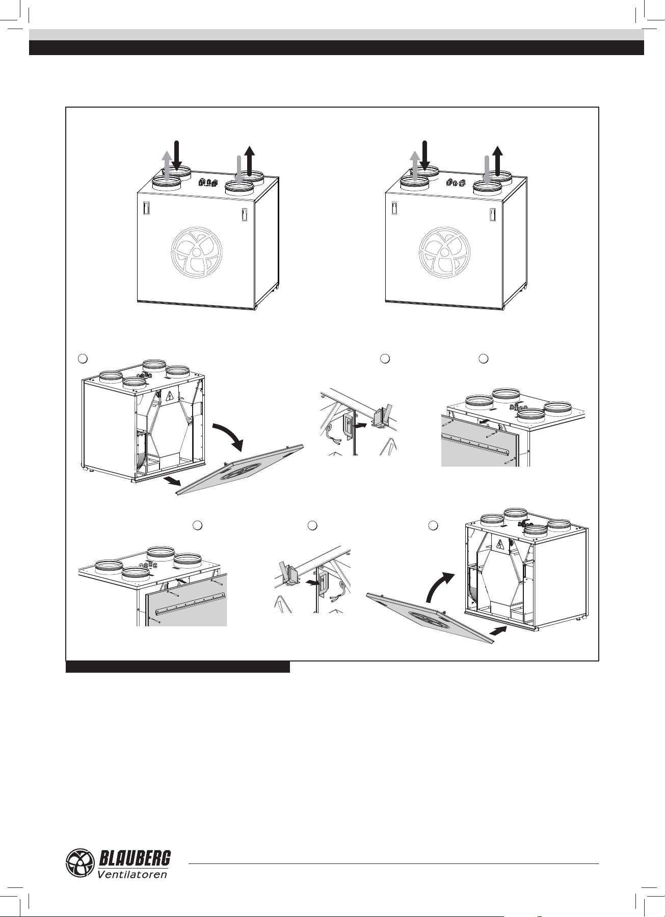
SERVICE SIDE CHANGE
Make sure of the correct unit service side selection (Fig. 12). Unit mounting position should enable free access to the removeable service panel for
maintenance and service operations.
Left-handed modication Right-handed modication
EXTRACT AIR EXHAUST AIR
INTAKE AIRSUPPLY AIR
INTAKE AIR
EXHAUST AIR
SUPPLY AIR
EXTRACT AIR
1
4
5 6
2 3
Fig. 12. Service side of the unit and the order of changing it
9
Page 10

KOMFORT EC S/SB
!
www.blaubergventilatoren.de
S11 CONTROL PANEL MOUNTING
The KOMFORT EC S S11 / KOMFORT EC SB S11 units have a wall-
mounted control panel S11 with a touch screen. The standard delivery set
includes a 10 m cable for connection of the unit and the control panel. The
control panel installation chart is shown in Fig. 13. The room temperature
sensor is integrated into the control panel. For that reason the control panel
must be installed in a temperature balanced place, at least 1 m away from the
heating equipment, doors and windows.
Fix the control panel to the wall using the screws and connect it to the air
handling unit using a supplied four-wire connecting cable.
For control panel mounting refer to Fig. 13.
WARNING
Make sure that the control panel is not damaged. Do not use a damaged control panel! Do not install the control panel on an uneven
surface! While tightening the screws do not apply excessive force to prevent the control panel casing deformation. Do not lay the
control panel cable in close proximity parallel to a power cable! Do not coil the cable from the control panel in loops while laying it.
1 2
3
Fig. 13. S11 control panel mounting
The S11 control panel includes a lithium cell CR1220 with a limited time
resource.
The battery keeps the internal clock running while the unit is
disconnected from power supply. If the unit is disconnected from power
supply and the battery is low, the clock stops and the day and time settings
are reset. This leads to incorrect date and time indication when the unit is on
and, as a result, to incorrect scheduled operation of the unit. In this case, the
battery should be replaced. To replace the battery use a new battery only.
Battery replacement:
1. Disconnect the air handling unit from power supply.
2. Remove the two screws in the bottom part of the casing.
4
3. Remove the Display. Replace the battery as shown.
4. 4. Assemble the control panel in the reverse order. If the terminal
block wires on the upper circuit board were unplugged make sure to reconnect them correctly. Failure to re-connect the wires properly will result in
operating failure of the equipment.
5. Connect the panel to the power supply and set the current date and
time.
10
Page 11

www.blaubergventilatoren.de
!
KOMFORT EC S/SB
S15 CONTROL PANEL MOUNTING
The KOMFORT EC S S15 / KOMFORT EC SB S15 units have a wall-
mounted control panel with a LED indication. The standard delivery set
includes a 10 m cable for connection of the unit and the control panel.
The control panel wall ush mounting is shown in Fig. 14. The control
panel wall surface mounting is shown in Fig. 15. Connect the control panel to
the air handling unit using a supplied connecting cable and x it to the wall
using one of the mounting boxes and the screws.
WARNING
Make sure that the control panel is not damaged. Do not use a damaged control panel! Do not install the control panel on an
uneven surface! While tightening the screws do not apply excessive force to prevent the control panel casing deformation. Do
not lay the control panel cable in close proximity parallel to a power cable! Do not coil the cable from the control panel in loops while laying it.
Wall ush mounting of the S15 control panel (Fig. 14):
1. Make a hole in the wall to install the control panel. Insert all the
necessary cables and wires into the hole, install the mounting box from the
delivery set in the wall.
2. Use a screwdriver to carefully undo the clips on the backside of the
control panel and remove the back cover.
3. Fix the back side of the casing to the mounting box through the
mounting holes, then connect the cable to the control panel in accordance
with the wiring diagram Fig. 18.
4. Fix the front side of the control panel using the latches.
1 2 3 4
Fig. 14. S15 control panel wall ush mounting
Wall surface mounting of the S15 control panel (Fig. 15):
1. Lead all necessary cables and wires to the control panel mounting place
and install the mounting box from the delivery set on the wall.
2. Use a screwdriver to carefully undo the clips on the backside of the
control panel and remove the back cover.
1 2 3 4
Fig. 15. S15 control panel wall surface mounting
3. Fix the back side of the casing to the mounting box through the
mounting holesusing two screws from the delivery set, then connect the
cable to the control panel in accordance with the wiring diagram Fig. 18.
4. Fix the front side of the control panel using the latches.
11
Page 12

KOMFORT EC S/SB
!
CONDENSATE DRAINAGE
www.blaubergventilatoren.de
The hole for the drain pipe is at the bottom of the unit. Remove the plug
from the hole, open the service panel and install the drain pipe from the
delivery set into the hole, then connect the drain pipe to the sewage system
using the KIT SFK 20x32 condensate drainage kit (available upon separate
order).
The condensate drainage system is designed for normal operation in
premises with air temperatures above 0 °C!
If the expected ambient air temperatures are below 0 °C the
condensate drainage system must be equipped with heat insulation and
pre-heating facilities.
Drain pipe
U-trap
Drain hose
Sewage system
min 3°
Fig. 16. Condensate drainage
WARNING
In case of several units mounting connect each unit to an individual U-trap.
Direct condensate drainage with no connection to the drain system is not allowed.
CONNECTION TO POWER MAINS
WARNING
Read the service instruction prior to any electric installations. Connection of the unit to power mains is allowed by a
quali ed electrician only.
The rated electrical parameters are stated on the rating plate. Any tampering with the internal connections is prohibited
and will void the warranty.
Connect the unit only to power mains with valid electric standards.
Follow the respective electric standards, safety rules (DIN VDE 0100), TAB der EVUs. The house cabling system must be
equipped with a magnetic trip automatic switch at the external input. The contact gap on all poles must be at least 3 mm (VDE
0700 T1 7.12.2 / EN 60335-1).
The automatic switch trip current must be not below the rated current consumption (ref. Table 1). Enable quick access to an
automatic switch installation place.
Cut power supply to the unit o by turning the automatic electric switch
QF to OFF position prior to any operations.
Take steps to prevent activation of the automatic switch before nishing
all the operations.
Connect the KOMFORT EC S S11 / KOMFORT EC SB S11 units to single-
phase AC 230 V/50-60 Hz power mains using the power cord with the Euro
Plug, pre-wired at the factory. The unit must be grounded in compliance with
the valid electrical standards of the user country!
Connect the unit to the terminal block X1, located in the control unit, in
12
compliance with the external connections wiring diagram. The unit has an
option of additional external controls connection to the X1 terminal block
(Fig. 17). The unit must be grounded in compliance with the valid electrical
standards of the user country!
QF
Page 13

www.blaubergventilatoren.de
KOMFORT EC S/SB
14151617
13
12
11
10no9
76 5
Х1
Gnd
Out
Gnd
Out
TE1
Design. Name Type Wire**
CCU* DX cooler N0 2x0,75 mm
SM1* Supply air damper actuator LF 230 2x0,75 mm
SM2* Extract air damper actuator LF 230 2x0,75 mm
PK1* Contact from re alarm panel N0 2x0,75 mm
P1 S11 control panel 4x0.25 mm
TE1 Outdoor air temperature sensor
*Is not included in the delivery set, should be ordered separately.
** Maximum connecting cable length is 20 m!
Fig. 17. External connections wiring diagram of the KOMFORT EC S S11 / KOMFORT EC SB S11 units
DO NOT LAY THE CONTROL PANEL CABLE IN CLOSE PROXIMITY
PARALLEL TO A POWER CABLE! DO NOT COIL THE CABLE FROM THE
AE+
E+
t C
P1
+12V
B
Gnd
BA
Gnd
+12V
c8no
CCU
(no-contact)
PK1
LLN LN
c
2121 21
L
N
SM2
LN
SM1
CONTROL PANEL IN LOOPS WHILE LAYING IT.
4
3PE2N1
LL
Power input
230 VAC
Recommended cross section of the data cable
2
2
2
2
2
between the control panel and the unit
Cable cross
section
Cable
length
ELECTRIC SHOCK HAZARD!
≥ 0,12 mm
up to 15 m up to 50 m
2
≥ 0,25 mm
2
Connect the unit KOMFORT EC S S15 / KOMFORT EC SB S15 to single-
phase AC 230 V/50-60 Hz power mains using the power cord with the Euro
Plug, pre-wired at the factory. The unit must be grounded in compliance with
the valid electrical standards of the user country!
The unit has an option of additional external controls connection to the
X2 terminal block, which is located on the hinged electrical mounting plate of
the control unit. Extra connections to the unit are shown in dotted lines in the
Wiring diagram, see Fig. 18.
• PK - connection of the automatic re extinguishing system con-
tact.
Upon connecting the automatic re extinguishing system contact remove
the jumper between the 1 and 2 terminals. In case of re the normally closed
dry contact breaks the control circuit from the central re- ghting board and
cuts o power supply to the unit.
• Connection of the external control unit contact, such as CO2
PK re alarm panel
(remove the jumper while
connecting the contact)
Humidity
sensor
+U
0-10V
3
21GND
230 V/ 50-60 Hz
XP
X1 X2
QF
L
sensor (NO, C).
Connect the CO2 sensor to the 6 and 7 terminals by using a normally opened
dry contact. If the contact is closed, the unit turns to the maximum speed.
FS2 (+U, 0-10 V, GND) humidity sensor connection.
Connect the FS2 humidity sensor (not included in the delivery set, can
be ordered separately) to the contact socket located on the side panel of the
control unit from the side of the extract pipe in accordance with the Wiring
diagram.
• Connection of outer air dampers (SM1 supply air damper, SM2
exhaust air damper).
The air dampers and the actuator are not included in the delivery set and
can be purchased separately. For controlling the air dampers use the LF 230
BELIMO electric actuator with a voltage of 230 V and an open-close controlling.
Connect the electric actuators to the 12 and 13 terminals (refer to the Wiring
diagram).
External device
NO contact
(CO2 sensor)
GND+U 0-10V NONPEPKPK C
GND Tx Rx +U
-
White
Control
panel
Tx Rx +
Green
Brown
Electric actuators
of the external air dampers
SM1
supply
L1 N
Yellow
exhaust
L1 N
SM-L13SM-N
SM2
234 1098765432111
1
Fig. 18. Wiring diagram of the KOMFORT EC S S15 / KOMFORT EC SB S15 units
12
13
Page 14

KOMFORT EC S/SB
UNIT CONTROL
The KOMFORT EC S S11 / KOMFORT EC SB S11 units are controlled from
the wall-mounted control panel with a sensor display (Fig. 19). Unit control and
adjustment of operating parameters are shown in Table 6. Possible error codes
are shown in Table 7. Factory settings are shown in Table 8.
Fig. 19. S11 control panel
Table 6. Unit control and adjustment of operating parameters of the unit with the S11 control panel
Function Indication
1 Main menu
The Main menu contains the date, current humidity, time, temperature and
set air ow.
MENU - access to the User menu, see clause 5.
AUTO - scheduled operation activation/deactivation.
TEMPERATURE - display of the current indoor temperature. After pressing
this button the Temperature Setting menu is opened, see clause 4.
ON/OFF - turning air handling unit ON/OFF or Standby mode activation.
TIMER - turning the timer on/o .
AIR FLOW - current fan speed display. The Fan Speed Setting menu is
accessible through this button, see clause 3.
The network connection status indicator is displayed:
www.blaubergventilatoren.de
− the unit is connected to network.
− the unit is disconnected from network.
2 Unit activation and deactivation
The unit is activated with ON
Press OFF for the unit deactivation or Standby mode activation. The
indicator changes its colour from red to green as the unit is turned on. In the
Standby mode the unit operates at the rst speed and set temperature, see
clause 12.
button.
14
Page 15

www.blaubergventilatoren.de
Table 6. Unit control and adjustment of operating parameters of the unit with the S11 control panel (continued)
Function Indication
3 Fan speed changeover
Fan speed setting:
Press the AIR FLOW button ;
The unit has four speed stages:
- Speed 1;
- Speed 2;
- Speed 3;
- Humidity Control mode. The fan speed is regulated depending on
the humidity setting. The humidity level is set via the Engineering menu, see
clause 14.
If the AUTO or TIMER mode is activated the current air
ow value is displayed in real time operation no matter of the set air ow
value.
KOMFORT EC S/SB
Set the required speed using the buttons or .
Then press ENTER
To return to the Main menu without saving changes press EXIT .
4 Temperature setting
Temperature setting:
Press the TEMPERATURE button
Select the set temperature type:
DUCT
ROOM
(temperature in the air duct);
(temperature in the room).
.
.
Set the desired temperature using or .
Then press ENTER
To return to the Main menu without saving changes press EXIT
.
.
15
Page 16

KOMFORT EC S/SB
Table 6. Unit control and adjustment of operating parameters of the unit with the S11 control panel (continued)
Function Indication
5 User menu
www.blaubergventilatoren.de
To enter the User menu press MENU
The User menu contains basic menu items and functions for parameters
setting:
ENG. MENU - access to the Engineering menu. The menu is passwordprotected.
AUTO ADJUST. - scheduled operation setting.
DATE/TIME - date and time setting.
TIMER ADJUST. - setting time and speed operation on timer basis.
MOTOR HOURS - setting lter replacement periodicity.
EXIT - return to the Main menu.
6 Engineering menu
in the Main menu.
To enter the Engineering menu press ENG. MENU
menu.
To access the Engineering menu enter the password. The
default setting is 1111.
Press OK.
To change the password use the RESET button.
Press RESET to clear the password eld.
To return to the User menu press EXIT .
If you forgot the user-de ned password, see clause 11 Password Change,
press and hold RESET until you hear a long sound signal (20 clicks,
approximately 20 seconds). The default password 1111 is set.
in the User
16
Page 17

www.blaubergventilatoren.de
Table 6. Unit control and adjustment of operating parameters of the unit with the S11 control panel (continued)
Function Indication
For navigating in the Engineering menu use the following buttons:
- moving upwards in the list.
- moving downwards in the list.
- select the value from the parameter list.
- return to the User menu.
KOMFORT EC S/SB
7 Air flow setting
Select the AIR FLOW SETTING item from the Engineering menu and
press ENTER .
Select the edited speed value (the selected value is highlighted with a
rectangle).
Use
stage.
The air ow is set as a percentage of the maximum performance of each fan.
To return to the Engineering menu without saving changes press EXIT
8 Temperature sensor
To select the heating control sensor from the Engineering menu select
the TEMPERATURE SENSOR submenu and press ENTER
Select a desired temperature sensor type.
Press ENTER to con rm.
To return to the Engineering menu without saving changes press EXIT
or buttons to set the air ow value for each fan speed
.
.
.
17
Page 18

KOMFORT EC S/SB
Table 6. Unit control and adjustment of operating parameters of the unit with the S11 control panel (continued)
Function Indication
9 Language selection
To select the control panel interface language select the LANGUAGE
www.blaubergventilatoren.de
submenu from the Engineering menu and press ENTER
Select the desired language from the list.
Press ENTER
To return to the Engineering menu without saving changes press EXIT
.
10 Extra options
Select the EXTRA OPTIONS submenu from the Engineering menu and
press ENTER .
The SUPPLY FAN OFF mode helps to prevent heat exchanger freezing
and requires disabling of the HEATING CONTROL parameter.
To activate the heat exchanger freezing protection function by means of
the supply fan deactivation set the HEATING CONTROL parameter value
to OFF. To proceed to the function setup set the SUPPLY FAN OFF MODE
parameter to ON.
TTo select a humidity sensor type set 1 for the duct sensor (exhaust duct)
or 2 for the room sensor in the HUMIDITY SENSOR SELECTION menu item.
For selecting the bypass operation mode set 1 in the BYPASS
OPERATION MODE to select the regular operation mode, which prevents
heat exchanger freezing, or 2 to enable bypass opening in the ventilation
mode.
To save the changes and return to the Engineering menu press EXIT
.
.
.
If the SUPPLY FAN OFF MODE parameter is set to ON the control panel
switches to the SUPPLY FAN OFF MODE setting.
Select an item by touching the respective eld: WORKING HOURS,
DOWNTIME and SWITCH-OFF TEMPERATURE (the temperature is set
according to the outdoor temperature sensor readings de ned in the range
from 0 °C to -30 °C).
Then use
Press ENTER
To return to the Engineering menu without saving changes press EXIT
.
11 Password change
Select the PASSWORD CHANGE submenu from the Engineering menu
and press ENTER
Then enter the new password for accessing the Engineering menu.
Press OK.
To re-enter the password press RESET. This operation clears the
ENTER NEW PASSWORD eld.
or buttons to set the desired value.
to con rm the parameters.
.
To return to the Engineering menu press EXIT .
18
Page 19

www.blaubergventilatoren.de
Table 6. Unit control and adjustment of operating parameters of the unit with the S11 control panel (continued)
Function Indication
12 Standby mode setting
Select the STANDBY MODE item in the Engineering menu and press
KOMFORT EC S/SB
ENTER
Use the buttons
window:
• 0 − deactivation of the unit.
• 1 − activation of the Standby mode. In the Standby mode the unit
operates at the rst speed at temperature set by
buttons in TEMPERATURE window.
Press ENTER .
To return to the Engineering menu without saving changes press EXIT
13 Display brightness adjustment
Select the BRIGHTNESS ADJUSTMENT submenu from the Engineering
menu and press ENTER
Then use the
Operation and Sleep modes. The panel switches to the Sleep mode 30
seconds after the last screen interaction.
Press ENTER to con rm.
To return to the Engineering menu without saving changes press EXIT
.
or to select 0 or 1 in the AIR FLOW
or
.
.
or buttons to set the brightness for the
.
14 Humidity setting
Select the HUMIDITY SETTING item in the Engineering menu and press
ENTER .
Select the humidity sensor type used to control the humidity:
• DUCT
included into the basic delivery set);
• ROOM humidity sensor
Then use
Press ENTER to con rm.
To return to the Engineering menu without saving changes press EXIT
.
In the Humidity Control mode the minimum air ow is equal to the air
ow at the low speed.
15 Error control
To receive information regarding the last error select ERROR CONTROL
(the duct humidity sensor is optional and is not
.
or buttons to set the desired humidity level.
submenu from the Engineering menu and press ENTER
The display shows the error date and code.
To return to the Engineering menu press EXIT .
Errors description is stated in Table 7.
.
19
Page 20

KOMFORT EC S/SB
Table 6. Unit control and adjustment of operating parameters of the unit with the S11 control panel (continued)
Function Indication
16 Control panel temperature sensor correction
To correct the panel temperature sensor indications select
TEMPERATURE CORRECTION submenu from the Engineering menu and
www.blaubergventilatoren.de
press ENTER
Then use
the room temperature sensor installed in the control panel casing.
The default factory setting for the temperature sensor correction is -6°C.
To return to the Engineering menu without saving changes press EXIT
.
17 Default settings
To reset the controller settings to the factory defaults select DEFAULT
SETTINGS submenu from the Engineering menu and press ENTER
To con rm the reset press ENTER
To return to the Engineering menu without saving changes press EXIT
.
The default settings are given in Table 8.
18 Current temperature review
.
or buttons to set the temperature correction for
.
.
To review the current temperatures select the CURRENT TEMPERATURES
submenu from the Engineering menu and press ENTER
The display shows all the current temperature information.
If any temperature sensor of the ventilation unit is missing its
con guration value is displayed as OFF.
To return to the Engineering menu press EXIT .
19 AUTO Mode (scheduled operation)
The AUTO mode enables scheduled operation of the ventilation unit. The
unit runs at the pre-set speed and temperature during the speci ed time
periods. The unit is in the Standby mode between the operating periods.
To activate the AUTO mode press AU TO
Main menu. Activation of the AUTO mode is con rmed with a tick —
.
. in the control panel
.
20
Page 21

www.blaubergventilatoren.de
Table 6. Unit control and adjustment of operating parameters of the unit with the S11 control panel (continued)
Function Indication
To set up the AUTO mode press the button to enter the User
menu and press AUTO ADJUST.
While the TIMER is active the AUTO mode is disabled due to a lower
priority.
Select the day to enable the AUTO mode. Upon entering the menu the
value is set to the current day. To change the day press the DAY eld.
KOMFORT EC S/SB
Then use the
temperature for the selected day by pressing the respective parameter eld.
Depending on the Standby mode settings, the unit remains in the
Standby mode or turns o between the operating periods.
To return to the Engineering menu and save changes automatically
press EXIT .
20 Timer
To activate the timer press TIMER
menu.
To set up the timer enter the User menu and press TIMER ADJUST.
or buttons to set the time, air ow and
in the control panel Main
.
Activation of the TIMER function is con rmed with a tick — .
If the AUTO and TIMER functions are activated synchronously, TIMER
function will operate as it supersedes the AUTO function.
The timer cannot be activated once the Humidity Control mode is on.
Use or buttons to set the time, air ow and air temperature
values.
Press ENTER to con rm the set parameters.
To return to the Engineering menu without saving changes press EXIT
.
21
Page 22

KOMFORT EC S/SB
Table 6. Unit control and adjustment of operating parameters of the unit with the S11 control panel (continued)
Function Indication
21 Motor hours
The MOTOR HOURS function enables the user to set up lter cleaning or
replacement periodicity. Upon expiration of the pre-set time the panel
displays a lter cleaning or replacement indicator. The indicator is displayed
every 24 hours.
To set up the MOTOR HOURS function enter the User menu and press
www.blaubergventilatoren.de
MOTOR HOURS
Then use the or buttons to set the lter replacement
interval.
The OPERATING HOURS window shows the time elapsed from the lter
installation.
Press RESET
To save the changes and return to the Engineering menu press EXIT
.
22 Errors
The control panel displays the following message in case of any
malfunctions in the ventilation unit operation.
.
after replacement of the lter.
To enter the ERROR LIST press EXIT .
The ERROR LIST can also be accessed from the Engineering menu.
The error code details are stated in Table 7.
The error message appears every 30 seconds until the system emergency
cause has been troubleshooted.
To reset the error alert restart the unit once the malfunction cause has been
eliminated.
22
Page 23

www.blaubergventilatoren.de
Table 7. Error code description for the S11 control panel
Error code Description
TE1 Outdoor temperature sensor malfunction.
TE2 Malfunction of the temperature sensor for heat exchanger freezing protection.
TE5 Duct temperature sensor malfunction.
TE6 Malfunction of the duct humidity sensor.
MIN Supply fan malfunction.
MEX Extract fan malfunction.
ERP Control panel communication error.
DI2 Fire alarm sensor actuation.
Table 8. Factory settings for the S11 control panel
Parameter Factory setting
Air ow rate 1
Temperature
Air ow setting
Temperature sensor Duct
Extra options
Supply Fan O mode
Standby mode setting
Display brightness adjustment
Humidity setting
Temperature sensor correction - 6 °C
Timer settings
Motor hours
Duct + 25 °C
Room + 20 °C
Air supply Speed 1 - 40 %, Speed 2- 70 %, Speed 3 - 99 %
Air extract Speed 1 - 40 %, Speed 2- 70 %, Speed 3 - 99 %
Heating control O
Supply Fan O mode O
Humidity sensor selection 2
BYPASS Operation mode 1
Working hours 20 minutes
Downtime 5 minutes
Switch-o temperature + 3 °C
Air ow rate 1
Temperature + 20 °C
Operation 50
Sleep 1
Duct 50 %
Room 50 %
Hours 01
Minutes 00
Air ow rate 1
Temperature + 20 °C
Setting 4000 hours
KOMFORT EC S/SB
23
Page 24

KOMFORT EC S/SB
www.blaubergventilatoren.de
The KOMFORT EC S S15 / KOMFORT EC SB S15 units are operated from
the wall-mounted control panel using the touch buttons (Fig. 20). Unit control
and adjustment of operating parameters are shown in Table 9. Factory settings
and parameters adjustment range are shown in Table 10.
Indication variants when the unit is o :
• The touch buttons on the control panel are not highlighted;
• Filter maintenance indicator and emergency indicator are highlighted
in the respective cases.
Touch button
High speed
Touch button
Medium speed
Touch button
Low speed
Fig. 20. S15 control panel
Table 9. Unit control and adjustment of operating parameters of the unit with the S15 control panel
Button Function
Unit activation:
Press one of three speed setting buttons. The selected button will be highlighted and the unit switches to the required speed.
Speed changeover:
Press the inactive speed setting button once. The selected button will be highlighted and the unit will switch to the required speed.
Unit deactivation:
To turn the unit o press the highlighted speed setting button.
Touch button
Filter maintenance
Touch button
Bypass damper control
Emergency indicator
Summer Cooling mode:
Press the touch button once. When the touch button is activated the display lights up and the unit switches to the Summer Cooling
mode in one of the ways, depending on the unit model:
• KOMFORT EC SB350 S15 and KOMFORT EC SB550 S15: the bypass damper is opened.
• KOMFORT EC S160 S15: the supply fan is turned o and only the extract fan is in operation.
Each time a touch button is pressed, the current unit status is changed and saved in the control panel memory.
Filter maintenance:
As the unit reaches the set value of operating hours, the touch button is highlighted to remind about cleaning or replacing of the
Table 10. Factory settings for the S15 control panel
Zero speed (the unit is o ) [%] 0 0 - 100
Low speed [%] 40 0 - 100
Medium speed [%] 70 0 - 100
High speed [%] 100 0 - 100
Unit speed with the closed dry contact of the external control unit [%] 100 0 - 100
Filter cleaning (replacement) interval 2160 (3 months) 0 - 10000
Humidity level [%] 60 30 - 80
lters.
After lter replacement or cleaning, reset the motor hours. Press and hold the touch button for 5 seconds. Resetting of the timer is
con rmed by the touch button light turning o .
Alarm:
In case of alarm, the alarm indicator is highlighted.
In case of alarm indication, contact the Seller!
Parameter Factory setting Adjustment range
24
Page 25

www.blaubergventilatoren.de
KOMFORT EC S/SB
The KOMFORT EC S S15 / KOMFORT EC SB S15 units are equipped with
a USB connector (Type B) and can be connected to a PC for con guring the
advanced settings in a special software (available for download on the website
eng.blaubergventilatoren.de).
To work with the pre-installed software connect the unit to a laptop or
to a PC via a USB cable with the Type A and Type B contact sockets. The USB
cable is not included in the delivery set. The software enables editing the unit
parameters (see Table 10).
The list of the adjustable parameters can be expanded in new versions of
the software.
Setting, troubleshooting and upgrading of the software version is made by
the servicetechnician.
The software is available for downloading on our website:
blaubergventilatoren.de.
TECHNICAL MAINTENANCE
WARNING
Cut power supply to the unit o by turning the automatic electric switch QF to OFF position prior to
any maintenance operations.
Take steps to prevent activation of the automatic switch before nishing all the operations.
USB Type A
USB Type B
Fig. 21. Connection of a PC to the units with the S15 control panel
Regular technical supervision and maintenance of the unit are required to
ensure the product long service life and non-stop operation.
Disconnect the unit from power supply prior to any maintenance
operations.
The unit must undergo technical maintenance 3 to 4 times a year.
The unit technical maintenance includes regular cleaning and other works:
1. Filter maintenance (3-4 times per year).
Dirty lters increase air resistance in the system and reduce supply air
volume. The lters require cleaning not less than 3-4 times per year. Vacuum
cleaning is allowed. After two consecutive cleanings lters must be replaced.
For new lters contact the Seller.
2. Heat exchanger maintenance (once a year).
Some dust may accumulate on the heat exchanger block even in case of
regular maintenance of the lters. To maintain the high heat recovery e ciency,
regular cleaning is required. To clean the heat exchanger pull it out, ush the
heat exchanger with warm detergent solution. After cleaning install the dry
heat exchanger back to the unit.
3. Fan maintenance (once a year).
Even in case of regular maintenance of the lters, some dust may
accumulate inside the fans and reduce the fan performance and supply air ow.
Clean the fans with a soft brush or cloth. Do not use water, aggressive
solvents or sharp objects as they may damage the impeller.
4. Technical maintenance of condensate drainage system (once a year).
The drain pipes may get clogged with the extracted particles. Pour some
water inside the drain pan to check the pipe for clogging. Clean the U-trap and
the drain pipe if required.
5. Technical maintenance of an air duct system (every 5 years).
Even regular ful lling of all the prescribed above maintenance operations
may not completely prevent dirt accumulation in the air ducts which reduces
the unit capacity. Duct maintenance means regular cleaning or replacement.
WARNING! Consider the unit sharp edges! Ful l maintenance
operations in work gloves!
6. Control unit maintenance (if necessary).
The control unit maintenance must be performed by an expert quali ed for
unassisted operations with electrical installations with the voltage up to 1000 V
after careful reading of the user’s manual.
Access to the control board of the control unit:
1 2
3
25
Page 26

KOMFORT EC S/SB
TROUBLESHOOTING
Table 11. Possible faults and troubleshooting
Fault Possible reason Troubleshooting
www.blaubergventilatoren.de
The fan(s) does not
start when the unit
is on
Automatic switch
tripping
Low air ow
Cold supply air
Noise, vibration
No power supply or wrong connection to power mains.
The motor is jammed, the impeller blades are soiled. Remove the motor jam, clean the impeller blades.
Short circuit in power grid. Turn the unit o and contact the unit Seller for fault diagnostics.
Too low set speed. Set higher speed.
The lters and the fans are soiled, the heat exchanger is soiled. Clean or replace the lters, fans and the heat exchanger.
The air dampers, the supply di users or the exhaust grilles are
closed or soiled.
The extract lter is soiled. Clean or replace the extract lter.
The heat exchanger is frozen.
The impeller is soiled. Clean the impeller.
The screw connection is loose. Tighten the screws.
Connect the unit to power supply. Troubleshoot the connection
error.
Open and clean the air dampers, the supply di users, the
exhaust grilles to ensure free air ow.
Check the heat exchanger condition. Turn the unit o if
required and restart it after the freezing danger is no longer
imminent.
No exible anti-vibration connectors. Install the exible anti-vibration connectors.
Condensate leakage The drain system is clogged, damaged or wrong installed.
Clean the condensate drain system. Check the drain hose slope.
Make sure the U-trap is lled with water and the drain system is
frost-protected.
26
Page 27

www.blaubergventilatoren.de
KOMFORT EC S/SB
ACCEPTANCE CERTIFICATE
The air handling unit with heat recovery
KOMFORT EC S160 S11 KOMFORT EC S160 S15
KOMFORT EC SB350 S11 KOMFORT EC SB350 S15
KOMFORT EC SB550 S11 KOMFORT EC SB550 S15
is recognized as serviceable.
The unit complies with the requirements according to the EU norms and directives, to the relevant EU-Low Voltage Equipment Directives, EU-Directives
on Electromagnetic Compatibility. We hereby declare that the unit complies with the essential protection requirements of Electromagnetic Council Directive
2004/108/EC, 89/336/EEC and Low Voltage Directive 2006/95/EC, 73/23/EEC and CE-marking Directive 93/68/EEC on the approximation of the laws of the
Member States relating to electromagnetic compatibility, which relate to electrical appliances used in set voltage classes.
This certi cate is issued following test carried out on samples of the product referred to above.
Approval mark Manufacturing date ____________________
CONNECTION CERTIFICATE
Heat recovery air handling unit
KOMFORT EC S160 S11 KOMFORT EC S160 S15
KOMFORT EC SB350 S11 KOMFORT EC SB350 S15
KOMFORT EC SB550 S11 KOMFORT EC SB550 S15
is connected to power mains in compliance with the operation manual requirements by the professional:
Company:
Expert’s Full Name
Date Signature
WARRANTY CARD
KOMFORT EC S160 S11 KOMFORT EC S160 S15
KOMFORT EC SB350 S11 KOMFORT EC SB350 S15
KOMFORT EC SB550 S11 KOMFORT EC SB550 S15
SELLER
PURCHASE DATE
REPRESENTATIVE IN EU
BLAUBERG Ventilatoren GmbH
Aidenbachstr. 52a,
D-81379 München,
Deutschland
27
Page 28

www.blaubergventilatoren.de
KOMFORT EC S/SB v.3(5+4) / EN
 Loading...