

BLAUBERG Ventilatoren Iso-K, Iso-K 160 4D, Iso-K 200 4E, Iso-K 200 4D, Iso-K 150 4E Operation Manual
...Page 1
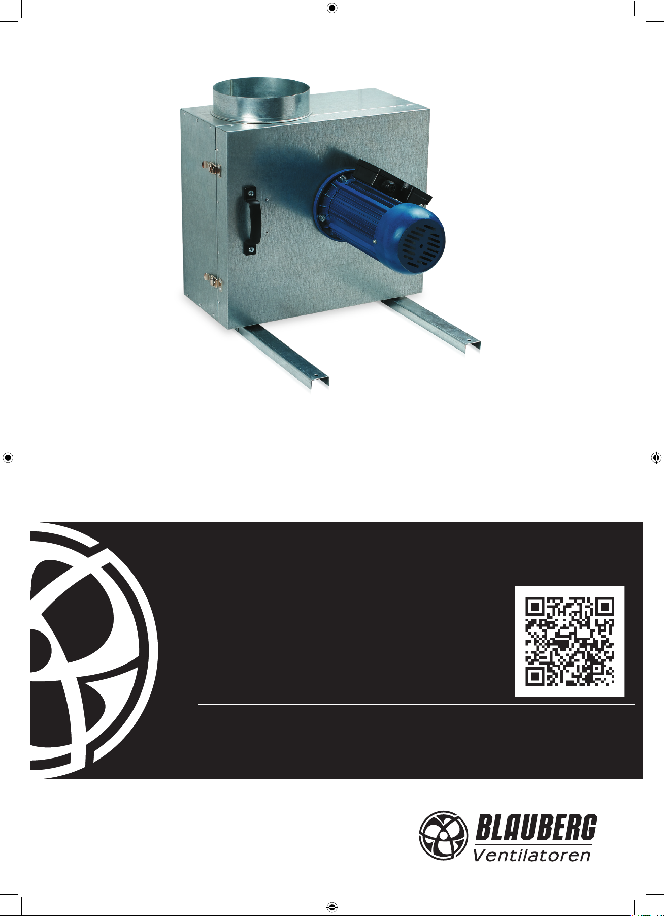
SOUND-INSULATED
FAN
Iso-K
OPERATION MANUAL
Iso-K_v.1(2)-EN.indd 1 10.08.2015 15:20:59
Page 2

www.blaubergventilatoren.de
Iso-K
CONTENT
Introduction 3
General 3
Safety rules 3
Transport and storage requirements 3
Manufacturer's warranty 3
Fan design 4
Delivery set 4
Technical data 5
Mounting and operation guidelines 6
Mounting sequence 6
Connection to power mains 7
Maintenance 8
Troubleshooting 8
Acceptance certicate 9
Connection certicate 9
Warranty card 9
2
Iso-K_v.1(2)-EN.indd 2 10.08.2015 15:20:59
Page 3
www.blaubergventilatoren.de
Iso-K
!
BLAUBERG Ventilatoren GmbH Company is happy to oer your attention
the sound-insulated fan BLAUBERG Iso-K.
INTRODUCTION
The present operation manual contains technical description, technical
data sheets, operation and mounting guidelines, safety precautions and
warnings for safe and correct operation of the fan.
GENERAL
The sound-insulated Iso-K fans are designed for hot and highly polluted
air extraction with the temperature up to 100 °C in high resistance condition.
The fans are used as a component of ventilation systems installed in:
- industrial kitchens;
- industrial bakeries;
- metal processing workshops (post-welding gas removal).
The fan is available for round air ducts Ø 150, 160, 200 and 315 mm.
The fan must be grounded.
The fan is allowed for operation only after nal mounting, that includes
installation of protecting devices in compliance with DIN EN ISO 13875 (DIN
EN ISO 12100) as well as other construction safety equipment.
The fan design is regularly improved, so some models can slightly dier
from those ones described in this operation manual.
SAFETY RULES
The fan complies with the requirements according to the EU norms
and directives, to the relevant EU-Low Voltage Equipment Directives, EUDirectives on Electromagnetic Compatibility.
All operations related to the electrical connection of the fan, like servicing
and repair works are allowed only after the disconnection from power mains.
All mounting and servicing operations are allowed for duly qualied
electricians with valid electrical work permit for electric operations at the
units up to 1000 V after careful study of the present operation manual.
Please follow the safety regulations and working instructions (DIN EN 50
110, IEC 364).
Make sure the impeller and the casing are not damaged before
connecting the fan to power mains. The casing internals must be free of any
foreign objects which can damage the impeller blades.
Disconnect the fan from power mains prior to any operations related to
the servicing and repair works. Make sure the rotating parts have come to a
full stop.
Take measures to prevent contact with the fan to avoid physical damages
during the fan test and start-up.
Misuse of the product or any unauthorized modication are not allowed.
The fan is designed for connection to ac single-phase or ac three-phase
power mains, see "Technical Data". The fan is rated for permanent operation
during non-stop power supply.
Take steps to prevent ingress of smoke, carbon monoxide and other
combustion products into the room through open chimney ues or other
re-protection devices. Sucient air supply must be provided for proper
combustion and exhaust of gases through the chimney of fuel burning
equipment to prevent back drafting. The maximum permitted pressure
dierence per living units is 4 Pa.
The transported air must not contain any dust or other solid impurities,
sticky substances or brous materials.
The fan is not designed for use in an inammable and explosive medium.
The transported medium must not have an aggressive eect on steel at
the temperature stated in the table 1 of the section “Technical data”.
The fan motor has F class winding insulation and IP 54 ingress protection
rating.
Do not close or block the intake or exhaust vent not to disturb the normal
air circulation.
Do not sit on the fan and do not put objects on the fan.
Follow the manual guidelines to ensure trouble-free operation and long
service life of the product.
STORAGE AND TRANSPORTATION RULES
Store the delivered fan in the manufacturer's original packing box in a dry
ventilated premise with the ambient temperature from +5°C up to + 40°C.
Store the fan in an environment with minimized risk of mechanical
damages, temperature and humidity uctuations. Store the fan inside a room
or under a shelter.
Transportation of the fan is allowed by any vehicle provided the fan is
transported in the original package and is protected against weather and
mechanical damages.
Use hoist machinery for handling and transportation to prevent possible
mechanical damages.
Full the requirements for transportation of the specied cargo type
during cargo-handling operations.
Do not expose the fan to extremely low or high temperatures.
MANUFACTURER'S WARRANTY
The fan complies with the requirements according to the EU norms
and directives, to the relevant EU-Low Voltage Equipment Directives, EUDirectives on Electromagnetic Compatibility.
The manufacturer hereby warrants normal operation of the fan over the
period of two years from the retail sale date provided observance of the
installation and operation regulations.
In case of failure due to faulty equipment during the warranty period the
consumer has the right to exchange it.
If case of no conrmation of the sale date, the warranty term shall be
calculated from the manufacturing date.
The replacement is oered by the Seller.
The MANUFACTURER shall not be liable for any damage resulting from
any misuse of or gross mechanic interference with the fan.
Full the operation manual requirements to ensure a trouble-free and
long service life of the fan.
WARNING
The product is not allowed for use by children and persons with
reduced physical, mental or sensory capacities, without proper practical
experience or expertise, unless they are controlled or instructed on the
product operation by the person(s) responsible for their safety.
Supervise the children and do not let them play with the product.
WARNING
Do not dispose in domestic waste. The product
contains in part material that can be recycled and in
part substances that should not end up as domestic
waste. Dispose of the fan once it has reached the end of
its working life according to the regulations valid where
you are.
3
Iso-K_v.1(2)-EN.indd 3 10.08.2015 15:21:00
Page 4

www.blaubergventilatoren.de
Iso-K
FAN DESIGN
Exhaust spigot
Casing
Centrifugal impeller
Electric motor
Supporting mounting frame
Vibration isolator
Fig. 1. Iso-K fan design
The steel is made of galvanized steel and is internally lled with 50 mm
thermal- and sound-insulating layer made of non-ammable mineral wool.
The fan casing is installed on a supporting mounting frame with integrated
vibration isolators.
The swivel motor-impeller block is attached to the swivel door which
facilitates the fan servicing.
The fan is equipped with a single- or three-speed motor with short circuit
rotor and a centrifugal impeller with forward curved blades.
The impeller is made of galvanized steel.
DELIVERY SET
fan - 1 item;
operation manual - 1 item.
Terminal box
The motor is equipped with ball bearings for longer service life and a
dynamically balanced turbine.
F class motor winding insulation and IP 54 ingress protection rating.
Overheating protection by built-in thermal switches with leads for
connection to external protection devices.
Smooth or step-up speed control with an auto transformer or frequency
inverter. Both available upon separate order.
Mounting to the wall is performed with the mounting angle bracket KS-ISK
(available upon separate order).
ATTENTION
Make sure the fan has no visible transport damages and check the ordered and the delivered goods for compliance.
4
Iso-K_v.1(2)-EN.indd 4 10.08.2015 15:21:00
Page 5

www.blaubergventilatoren.de
Iso-K
L4
D
TECHNICAL DATA
Table 1. Technical data
Parameters
Voltage, 50 Hz [V] 1 ~ 230 3 ~ 380 1 ~ 230 3 ~ 380 1 ~ 230 3 ~ 380
Power [W] 180 180 550 750 1500 1500
Current [A] 1.7 0.6 3 2 11 3.4
Max. air ow [m3/h] 700 730 1600 1650 3400 3500
RPM [min-1] 1450 1455 1475 1465 1500 1470
Noise level, 3 m [dBA] 41 41 45 45 51 51
Max. transported air temperature [°C] -20 ... +100 -20 ... +100 -20 ... +100 -20 ... +100 -20 ... +100 -20 ... +100
Ingress Protection Rating IP 54 IP 54 IP 54 IP 54 IP 54 IP 54
Table 2. Overall dimensions
Type
Iso-K 150 4E
Iso-K 150 4D
Iso-K 160 4E
Iso-K 160 4D
Iso-K 200 4E
Iso-K 200 4D
Iso-K 250 4E
Iso-K 250 4D
ØD B B1 H H1 L L1 L2 L3 L4
150 410 330 540 365 525 500 470 475 205 17
150 410 330 540 365 525 500 470 475 205 17
160 410 330 540 365 525 500 470 475 205 17
160 410 330 540 365 525 500 470 475 205 17
200 485 365 600 425 625 600 570 515 235 25
200 485 365 600 425 625 600 570 515 235 25
250 575 435 665 505 700 675 645 620 285 40
250 575 435 665 505 700 675 645 620 285 40
Iso-K 150 4E
Iso-K 160 4E
Iso-K 150 4D
Iso-K 160 4D
Dimensions [mm]
Iso-K 200 4E Iso-K 200 4D Iso-K 250 4E Iso-K 250 4D
Weight [kg]
H1
B1
Fig. 2. Iso-K fan overall dimensions
L2
H1
L4
D
H
B
L3
D
L1
L
5
Iso-K_v.1(2)-EN.indd 5 10.08.2015 15:21:01
Page 6

www.blaubergventilatoren.de
Iso-K
MOUNTING AND OPERATION GUIDELINES
WARNING
The fan is designed for connection to round air ducts on both sides of the
fan.
The special xing brackets in the fan casing enable selecting the most
suitable fan installation position.
If the fan is connected through the exible anti-vibration connectors the
fan must be secured to a mounting surface with supports, hanger brackets
or brackets.
The air motion direction in the system must match the pointer on the fan
casing.
Before starting mounting:
Read carefully the fan mounting, start-up, operation and servicing instructions;
Check the fan for possible transport damages.
Follow the safety regulations during the fan start-up and operations.
MOUNTING SEQUENCE
1. Cut o power supply.
Install the fan to ensure sucient and quick access for servicing and repair
operations.
The fan must be grounded.
To reduce air turbulence related pressure losses connect a straight air duct
to the fan of the length equal to min. 1 air duct diameter on the intake side
and min. 3 air duct diameter on the exhaust side.
Power is supplied either through the external terminal box.
Mounting of the fan on the wall with the KS-ISK mounting angle brackets
is shown in g. 3 (available upon separate order).
4. Install the fan on the KS-ISK mounting brackets and x it using
appropriate fasteners.
QF
2. Mark and drill the holes on the mounting surface for the fan mounting.
3. Fix the KS-ISK mounting angle brackets on a mounting bracket using
appropriate fasteners, for example, expansion anchors.
5. Install accessories, i.e. install a backdraft damper into the fan spigot.
6. Connect air ducts to the fan and x those with clamps (available upon
separate order).
6
Iso-K_v.1(2)-EN.indd 6 10.08.2015 15:21:01
Page 7

www.blaubergventilatoren.de
Iso-K
W1V1U1
W2 U2 V2
X1
C1
QF
N
L
~230 V
50 Hz
X1 – fan terminal block
С1 – capacitor
QF – automatic switch (not included into the delivery set)
W1V1U1
W2 U2 V2
X1
C1
QF
N
L
~230 V
50 Hz
~380 V / 50 Hz
X1 – fan terminal block
С1 – capacitor
QF – automatic switch (not included into the delivery set)
X1 – fan terminal block
QF – automatic switch
(not included into the delivery set)
W1V1U1
W2 U2 V2
X1
QF
L1 L3L2
CONNECTION TO POWER MAINS
!
WARNING
Read the operation manual prior to any electric installations. Connection of the fan to power mains is allowed by a qualied
electrician only.
The rated electrical parameters of the fan are stated on the rating plate. No modications of internal connections are
allowed and will result in void warranty.
Connect the fan only to power mains with valid electric standards.
Follow the respective electric standards, safety rules (DIN VDE 0100), TAB der EVUs.
The house cabling system must be equipped with an automatic switch at the external input. Connect the fan to power
mains through the automatic switch. The contact gap on all poles at least 3 mm (VDE 0700 T1 7.12.2 / EN 60335-1).
The automatic switch trip current must be in compliance with the fan current consumption, refer Table 1. Install the
automatic switch to ensure prompt access.
The fan is rated for connection to single-phase alternating current power
mains 230 V / 50 Hz.
The recommended rated automatic switch trip current for ISO-K fans is
stated in Table 3.
The electric connections must be performed with insulated, durable and
heat-resistant conductors (cables, wires).
The recommended conductor cross section is stated in Table 3.
The wiring diagram for connection of the single-phased fans is shown in
g. 3. The wiring diagram for connection of the three-phased fans is shown
in g. 4.
Cut power supply to the fan o by turning the automatic electric switch
QF to OFF position. Take steps to prevent activation of the automatic switch
prior to nishing mounting.
Connection to power mains of the basic fan model with a terminal box
is as follows:
1. Cut o power supply to the fan by turning the automatic switch QF to
OFF position.
2. Remove the screws that x the terminal box cover and take o the
cover.
Table 3. Recommended automatic switch trip current and cable cross
section.
Model
Iso-K 150 4E
Iso-K 150 4D
Iso-K 160 4E
Iso-K 160 4D
Iso-K 200 4E
Iso-K 200 4D
Iso-K 250 4E
Iso-K 250 4D
Rated automatic
switch trip current
[A]
2 2 x 1.5
1 3 x 1.5
2 2 x 1.5
1 3 x 1.5
8 2 x 1.5
3.15 3 x 1.5
12.5 2 x 1.5
4 3 x 1.5
Recommended cable n x S,
n – wire number;
S – cross section, mm
2
3. Route the electric cable to the terminal box through the electric lead-in
and connect the cable wires to the input terminal box in compliance with the
wiring diagram, g. 3, 4. Fix the cable with nuts. Re-install the terminal box
cover and x it with screws.
4. Turn the fan on by turning the automatic switch QF to ON position.
Iso-K_v.1(2)-EN.indd 7 10.08.2015 15:21:02
Fig. 3. Wiring diagram for single-phase fans
Fig. 4. Wiring diagram for three-phase fans
7
Page 8

www.blaubergventilatoren.de
Iso-K
MAINTENANCE
ATTENTION
Cut power supply to the fan o by turning the automatic electric switch QF to OFF position.
Take steps to prevent activation of the automatic switch prior to nishing maintenance.
QF
Disconnect the fan from power mains prior to any operations related to
servicing and repair works. Make sure the rotating parts have come to a full
stop.
The fan technical maintenance consists in the periodic cleaning of the
fan surfaces.
The impeller blades required thorough cleaning once in 6 months.
Cleaning procedure:
cut off power supply to the fan;
QF
open the fan swivel panel;
TROUBLESHOOTING
clean the impeller blades with a dry soft brush or compressed air.
Avoid liquid dripping on the motor and inside the electronic compartment.
While cleaning the fan be careful not to displace the impeller counter
weights. After cleaning perform all the operations reverse.
Table 4. Error list and troubleshooting
Fault Possible reason Remedy
The fan does not
operate.
Automatic switch
tripping.
Noise, vibration.
No power supply or connection error.
Jammed motor, soiled impeller blades. Remove the motor jam, clean the impeller blades.
Short circuit in power grid. Turn the fan o and contact your seller for troubleshooting.
The impeller is soiled. Clean the impeller.
The screw connection is loose. Tighten the fastening screws.
No exible anti-vibration connectors are installed. Install the exible anti-vibration connectors.
Make sure of correct power supply, otherwise troubleshoot the
connection error.
8
Iso-K_v.1(2)-EN.indd 8 10.08.2015 15:21:03
Page 9

www.blaubergventilatoren.de
Iso-K
ACCEPTANCE CERTIFICATE
Sound-insulated fan
150
125
Iso-K
160
200
250
is recognizes as serviceable.
The product complies with the requirements according to the EU norms and directives, to the relevant EU-Low Voltage Equipment Directives, EU-Directives
on Electromagnetic Compatibility.
We hereby declare that the product complies with the essential protection requirements of Electromagnetic Council Directive 2004/108/EC, 89/336/EEC
and Low Voltage Directive 2006/95/EC, 73/23/EEC and CE-marking Directive 93/68/EEC on the approximation of the laws of the Member States relating to
electromagnetic compatibility.
This certicate is issued following test carried out on samples of the product referred to above.
Approval mark Manufacturing date ____________________
4E
4D
CONNECTION CERTIFICATE
Sound-insulated fan
150
125
Iso-K
160
200
250
is connected to power mains in compliance with this operation manual requirements by the professional:
Company:
Name:
Date Signature
4E
4D
WARRANTY CARD
150
Iso-K
125
160
200
250
4E
4D
SELLER
SALES DATE
REPRESENTATIVE IN EU
Blauberg Ventilatoren GmbH
Aidenbachstr. 52a,
D-81379 München,
Deutschland
9
Iso-K_v.1(2)-EN.indd 9 10.08.2015 15:21:03
Page 10

www.blaubergventilatoren.de
Iso-K
NOTES
_______________________________________________________________________________________
_______________________________________________________________________________________
_______________________________________________________________________________________
_______________________________________________________________________________________
_______________________________________________________________________________________
_______________________________________________________________________________________
_______________________________________________________________________________________
_______________________________________________________________________________________
_______________________________________________________________________________________
_______________________________________________________________________________________
_______________________________________________________________________________________
_______________________________________________________________________________________
_______________________________________________________________________________________
_______________________________________________________________________________________
_______________________________________________________________________________________
_______________________________________________________________________________________
_______________________________________________________________________________________
_______________________________________________________________________________________
_______________________________________________________________________________________
_______________________________________________________________________________________
_______________________________________________________________________________________
_______________________________________________________________________________________
_______________________________________________________________________________________
_______________________________________________________________________________________
_______________________________________________________________________________________
_______________________________________________________________________________________
_______________________________________________________________________________________
_______________________________________________________________________________________
_______________________________________________________________________________________
_______________________________________________________________________________________
_______________________________________________________________________________________
_______________________________________________________________________________________
_______________________________________________________________________________________
_______________________________________________________________________________________
_______________________________________________________________________________________
_______________________________________________________________________________________
_______________________________________________________________________________________
_______________________________________________________________________________________
_______________________________________________________________________________________
_______________________________________________________________________________________
_______________________________________________________________________________________
_______________________________________________________________________________________
_______________________________________________________________________________________
_______________________________________________________________________________________
_______________________________________________________________________________________
_______________________________________________________________________________________
_______________________________________________________________________________________
_______________________________________________________________________________________
_______________________________________________________________________________________
_______________________________________________________________________________________
10
Iso-K_v.1(2)-EN.indd 10 10.08.2015 15:21:03
Page 11

www.blaubergventilatoren.de
Iso-K
NOTES
_______________________________________________________________________________________
_______________________________________________________________________________________
_______________________________________________________________________________________
_______________________________________________________________________________________
_______________________________________________________________________________________
_______________________________________________________________________________________
_______________________________________________________________________________________
_______________________________________________________________________________________
_______________________________________________________________________________________
_______________________________________________________________________________________
_______________________________________________________________________________________
_______________________________________________________________________________________
_______________________________________________________________________________________
_______________________________________________________________________________________
_______________________________________________________________________________________
_______________________________________________________________________________________
_______________________________________________________________________________________
_______________________________________________________________________________________
_______________________________________________________________________________________
_______________________________________________________________________________________
_______________________________________________________________________________________
_______________________________________________________________________________________
_______________________________________________________________________________________
_______________________________________________________________________________________
_______________________________________________________________________________________
_______________________________________________________________________________________
_______________________________________________________________________________________
_______________________________________________________________________________________
_______________________________________________________________________________________
_______________________________________________________________________________________
_______________________________________________________________________________________
_______________________________________________________________________________________
_______________________________________________________________________________________
_______________________________________________________________________________________
_______________________________________________________________________________________
_______________________________________________________________________________________
_______________________________________________________________________________________
_______________________________________________________________________________________
_______________________________________________________________________________________
_______________________________________________________________________________________
_______________________________________________________________________________________
_______________________________________________________________________________________
_______________________________________________________________________________________
_______________________________________________________________________________________
_______________________________________________________________________________________
_______________________________________________________________________________________
_______________________________________________________________________________________
_______________________________________________________________________________________
_______________________________________________________________________________________
_______________________________________________________________________________________
11
Iso-K_v.1(2)-EN.indd 11 10.08.2015 15:21:03
Page 12

www.blaubergventilatoren.de
Iso-K / v.1 (2) / EN
Iso-K_v.1(2)-EN.indd 12 10.08.2015 15:21:03
 Loading...