

Page 1
1
www.blaubergventilatoren.de
CD-1
Wall mounted CO2 sensor with 1 analog output & 1 on/o output
User’s Manual
Parameters Value
Power supply/Consumption 24VAC (50/60Hz ± 10%), 24VDC / max. 1.6 W
Gas sensing element Non-dispersive infrared detector (NDIR) with self-calibration system
CO2 measuring range 0–2,000 ppm (parts per million)
Accuracy at 25 °C, 2,000 ppm ±30 ppm + 3% of reading
Response time <2 minutes
Warm up time for each turning-on
2 hours (first time)
2 minutes (operation)
Analogue output 0–10VDC (default), 4–20mA selectable by jumpers
On/Off output
1X2A switch load
Four set points selectable by jumpers
6 LED lights
1st green indicator lights when CO2 concentration is below 600 ppm
1st and 2nd green indicators light when CO2 concentration is 600-800 ppm
1st yellow indicator lights when CO2 concentration is 800-1200 ppm
1st and 2nd yellow indicators light when CO2 concentration is 1200-1400 ppm
1st red indicator lights when CO2 concentration is 1400-1600 ppm
1st and 2nd red indicators light when CO2 concentration is above 1600 ppm
Operation conditions/
Storage regulations
0–50 °C; 0–95% RH non condensing/
0–50 °C
Net weight/Dimensions 120g/100mm × 80mm × 30mm
Mounting standard 65mm × 65mm wire box, or hang on a nail
Standard Approval CE
SPECIFICATIONS
MOUNTING AND WIRE CONNECTION
• Notice the supply power voltage of the
sensor: 24VAC/VDC. Do not install the sensor
on voltages higher than marked on the
sensor.
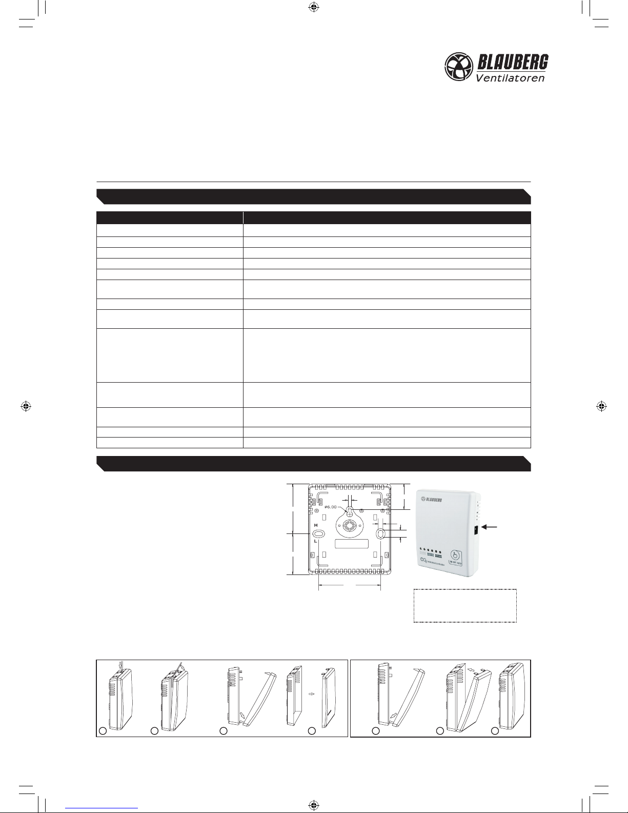
• Follows the steps in fig. 2 to remove the cover.
• Mount the sensor on the place where you
want to detect CO2 level. Do not mount it
near diffuser or any steam source, in direct
sunlight.
• Mount the wall plate first, there are two
dimensions available (see fig. 1). Place the
sensor against the wall at selected location;
make sure wires pass through the notch on
the wall plate.
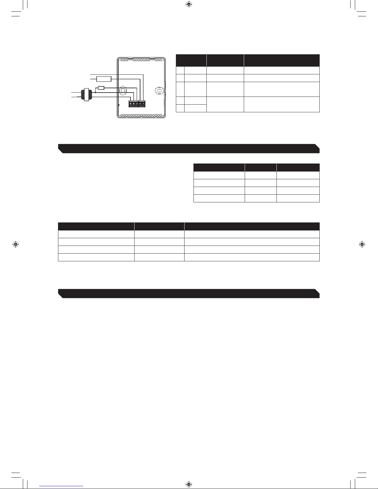
• Connect wires to terminal strips (see fig. 4).
Make sure wiring connection is correct and
secure.
• Follows the steps in fig. 3 to close the cover.
Fig. 2 Fig. 3
Fig. 1 Dimensions
60.00
45.00
55.00
28.00
3.00
4.50
8.00
1 2 3 4 5 6 7
Touch button for switching on/
off/auto operation modes of
the fan.
Socket for a
12~24VAC/VDC
power adapter
CD-1_EN.indd 1 26.10.2015 16:27:48
Page 2
2
Fig. 4 Wiring
Transformer
24VAC
1 2
4 5
<240VAC/30VDC/2A
Transformer
supply
Power
3
device
Controlled
L2
L1
General
CO
2
mA
4-20mA
Connection
Terminal
Function Electrical Data
1 G+ Power (+) 24VAC/24VDC+
2
G0 Power ground (-) 24VAC/24VDC
3
OUT Analog output (+)
0–10VDC (default), 2–10VDC, 0–20mA,
4–20mA=0–2,000 ppm (CO2)
4 Fan
Relay output
<240VAC/30VDC 2A switching
current (resistance load)
5 Common
SELECT OUTPUT
IMPORTANT INSTRUCTIONS
• Power off first and remove the face cover, you’ll see a
set of short-circuit block jumpers in the middle of the
right side of PCB board. From left to right, it’ s J1–J5
and S1–S2. Choose the type of analogue output or
CO2 level to control the relay following instructions
shown in table shown in table below (J2 & J3 are just
for manufacture test. Please don’ t change it!).
1. Don’ t shake or hit the sensor too much during shipment or mounting to protect the internal infrared CO2 sensor from
any damage and excursion of infrared receiver.
2. When:
a. First use CO2 sensor, or
b. Reuse CO2 sensor after a long time unused or
c. CO2 measurement is proved to be incorrect (by comparing with the measurement of other CO2 sensors,
or put the sensor outdoors and its measurement is away from the range of 350ppm–450ppm, which is the normal
ambient CO2 concentration, then let the self-calibration system work as follows:
Keep the CO2 sensor energized continuously for at least 2 days to let CO2 sensor’s self-calibration system operate properly.
After more than 2 days’ calibration, if the measurement (indicated by the analog output) of the
CO2 sensor still exceeds over the accuracy, you need to let it self-calibrated for a longer time. Here’s a typical
14-day calibration solution: During a 14-day period, place the CO2 sensor twice outdoors or in unoccupied places where
CO2 level is around 400 ppm. Each time let it be there for more than 4 hours and then check the CO2 measurement via
analogue output. If the CO2 measurement is in its accuracy limit, it indicates the measurement is correct.
Notice:
a. Using of cellular telephones or radio transceivers about 60 cm away from the sensor during calibration process could
cause sensor interference, calibration errors and affect sensor accuracy. Please refrain from using these devices during
calibration of the sensor.
b. When checking the analog output, please avoid breathing out directly to the CO2 sensor. It’s recommended to connect
the output terminals with the extending wires with length of more than 1 meter. When the CO2 sensor indications become
stable after more than 10 minutes turning-on, check the analog output through the extending wires to avoid influence of
breathing process on CO2 concentration.
Jumper S1-S2 Jumper J1 Analog outputs
Lower two pins blocked disconnected 0–10VDC (default)
Upper two pins blocked disconnected 0–20mA
Lower two pins blocked connected 2–10VDC
Upper two pins blocked connected 4–20mA
Jumper J4-J5 CO2 level The relay turns on /turns off
J4-disconnected; J5-disconnected 800 ppm CO2>800 ppm, the relay on; CO2 <700 ppm, the relay off
J4-connected; J5-disconnected 1,000 ppm CO2>1,000 ppm, the relay on; CO2 <900 ppm, the relay off
J4-disconnected; J5-connected 1,200 ppm (default) CO2>1,200 ppm, the relay on; CO2 <1,100 ppm, the relay off
J4-connected; J5-connected 1,400 ppm CO2>1,400 ppm, the relay on; CO2 <1,300 ppm, the relay off
CD-1V1(2)EN
CD-1_EN.indd 2 26.10.2015 16:27:50
 Loading...