

Page 1
www.BLATA .com
User manual for the minibike Blata Ultima EN
ver. 02-2009/12/11
Page 2
SAFETY WARNING
Pay extra attention when performing maintenance and service of the
machine and maintain the safety warning and instructions stated below!
Before putting the minibike into operation, familiarize yourself carefully with instructions
about its proper use and maintain them in the interest of your safety and also the safety of
others. The manufacturer and distributor are not responsible for damages, or eventual injuries caused by procedures which are contrary to the manual and the safety instructions.
This vehicle is not designated for operation on public communications!
The use of worn and incorrectly inated tires, or tires that are of incorrect size, decreases stability and can cause an accident.
Brake uid causes damage to skin and eyes. When working with the brake uid always
use protective gloves and protect the eyes by using safety glasses.
The bad condition of the brake pads can be a cause of decreased effectiveness of the
brake and can therefore be a cause of an accident during riding. Therefore inspect and
replace the brake pads according to the instructions of this manual.
Neglect of inspection and maintenance increases the risk of an accident during riding.
Before every ride inspect the brake cable / lines and the effectiveness of the brake.
The incorrect adjustment of the chain and the use of a chain that is in a bad technical state increases the
risk of an accident, therefore perform an inspection and an adjustment of the chain before every ride.
It is necessary to let the hot parts of the engine and exhaust cool down before performing any manipulation in that area, such as for example the replacement or cleaning
of the spark plug, the lubricating or tightening of the chain.
Serious injury can occur while performing maintenance, with the engine running, by
the hands or parts of the clothing being caught into the moving parts. Always turn the
engine off and let it cool down before performing inspections or maintenance.
Do not overestimate your capabilities or the capabilities of the machine while riding. Adjust the riding to the
conditions on the riding track. In this way you will avoid unnecessary injuries and damage to the machine.
The fuel and its fumes are highly toxic and ammable. Careless manipulation with the
fuel can result in burns or poisoning. Therefore:
- while lling up the fuel always turn the engine off and keep away from open ame
and sparks; don‘t smoke
- only ll up the fuel while outside or in proper ventilated areas
- immediately wipe off spilled fuel
- make sure that children and animals are kept at a safe distance
Perform the prescribed inspection of the vehicle before each ride, see “Regular maintenance”. The nonperforming of the prescribed regular inspections and maintenance
increases the risk of an accident and damage to the vehicle.
Serious injury can occur during careless manipulation with this machine. The rider
can decrease these eventual risks to a minimum by using safety equipment. The rider
must properly use the safety helmet, eye protection, protective gloves, elbow and knee
protectors and suitable footwear. Avoid uneven surfaces and obstacles. Hold the handlebars with both hands while driving. Have both feet placed on the foot pegs.
Page 3

PACKAGE CONTENT
GENERAL WARNING
The complete delivery of the minibike Blata Ultima is composed of:
- Transport packing - carton box
- Minibike
- User manual
- Stand
- Document of payment
- The packing can optionally contain further additional or spare parts which were
ordered together with the minibike
During unpacking it is necessary to follow the instructions stated in the chapter Preparation of the minibike for operation. Immediately report to the transport company
any visible damage to the delivery. Check the package content with the order and
immediately report any defects to the seller, eventually to the manufacture. That is not
possible to acknowledge a claim made later.
- The manufacturer is presenting the user manual with the purpose of providing the user
with all the necessary information and instructions for the effective use of the machine.
- The user manual was elaborated by the manufacturer and makes up an inseparable
part of the machine‘s accessories. The information contained in the user manual is
designated for qualied workers.
- The use of this manual is in the full responsibility of the user. It is necessary to
consider all the operations, which are not described here, as being forbidden. The
service worker performing such operations will carry all the responsibility for the
results of his actions. It is necessary for the user manual to be stored for possible
future references.
- The actual version of the manual, corresponding to your minibike, is identied on
the front page of the manual.
- The responsibility of the user (operator) and the service personnel is to properly
familiarize themselves with this manual before they begin using the equipment.
This will eliminate mistakes which could occur during its installing and also during
its use. Therefore do not attempt to bring the equipment into operation prior to
properly studying this manual.
- The manual contains everything that is necessary to know for the correct setting
up and operation of the machine. You will prevent losses and will be satised
with the functionality of the machine and its long service life if you maintain all the
instructions in the manual.
- The manual also contains important information about work safety, assembly,
operation and maintenance and it is necessary to consider it as a part of the equip-
ment. The failure-free and safe work with the equipment and its service life signi-
cantly depends on its correct and thorough maintenance.
- The operator of the equipment must be familiarized with its functions and controls
and must be instructed about safety.
- Follow the safety instructions during work in order to avoid the danger of the
injury of yours or persons nearby.
- The manufacturer is not responsible for the damages caused by procedures
which are contrary to this manual and safety instructions.
- Please read this user manual carefully before transporting the machine, putting it
into operation, using it, performing maintenance or performing any other inter vention. Make sure that it is stored near the machine so it is constantly available.
- Do not, under any circumstances, use the machine in any other way than is descri bed in this manual. The manufacturer does not take over any responsibility for da mages caused to property or the health of persons, which are the result of not fol lowing the safety regulations.
- Use all the necessary protective means such as clothing, protective gloves and
safety glasses.
- Do not allow unauthorized persons to perform repairs, maintenance or other activi ties of any type on the machine.
- Transportation and activities related with the installing and assembly should be
performed only by persons which have the necessary technical competence.
- All works on the electrical system should only be performed by competent persons.
- Always rst turn off the engine and shut off the fuel supply during any type
of a malfunction, cleaning etc.
- It is necessary to bring attention to the danger resulting from certain types of
clothing, such as sleeves which can be caught into objects that may cause injury
to the operator, if they are wearing it during work. Due to this reason it is desirable
for the operator of the machine to not use dangerous objects such as, for example:
rings, a watch, bracelets, clothing with wide sleeves, loose belts, ties and generally
any clothing which can loosely hang and which can be caught by the movable parts
of the machine. Persons with long hair must have it tied up, eventually hidden under
the helmet.
FORBIDDEN USE
The following activities are not allowed:
- The use of the machine without the protective elements or the removal of these
protective elements.
- The use of the machine without safety equipment, as it is described in the safety
warnings.
- It is forbidden to perform any modications to the machine.
- Other use than that which is described in the user manual.
- Allowing children and other unauthorized persons access to the machine.
- Using any other spare parts than original spare parts.
- Rough handling of the machine, mainly its overloading, dangerous riding, riding on
an unsuitable surface etc.
- Endangering other persons and animals during riding.
- Using the machine when it is damaged or improperly set up.
- Usin g the m ach ine w hen u nde r the i nfl uen ce of a lco hol o r oth er na rco tic a nd
psychotropic substances.
- Using the machine by injured, physically or psychologically incompetent persons.
All damages to health and property, which are the result of incorrect use of the
machine, will be the sole responsibility of the user.
Page 4

Hydraulic brakes
Hose
Hydraulic brake lever
Hydraulic brake caliper
Mechanical front brake
Mechanical rear brake
Mechanical brakes holder
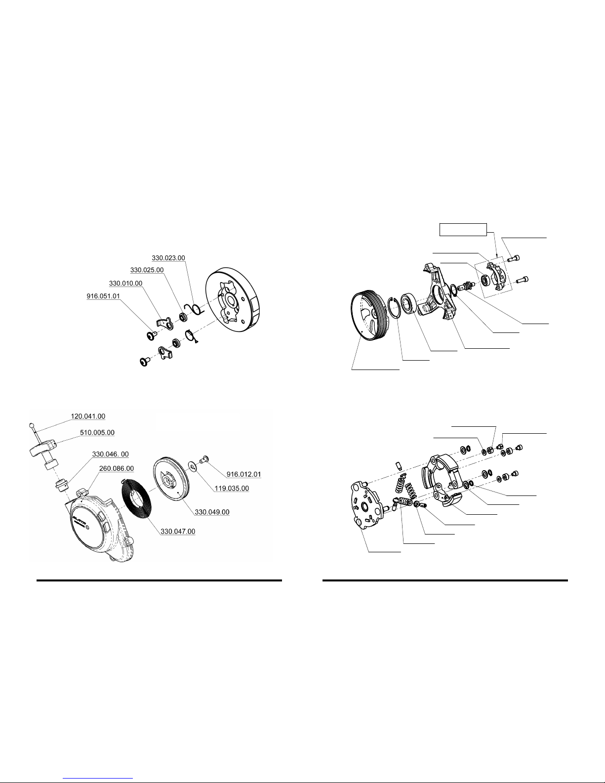
Engine - complete
Engine R40, RM9, RM14
Engine W40
Engine W50
Rotor
Starter case - complete
Clutch case - complete
Clutch - complete
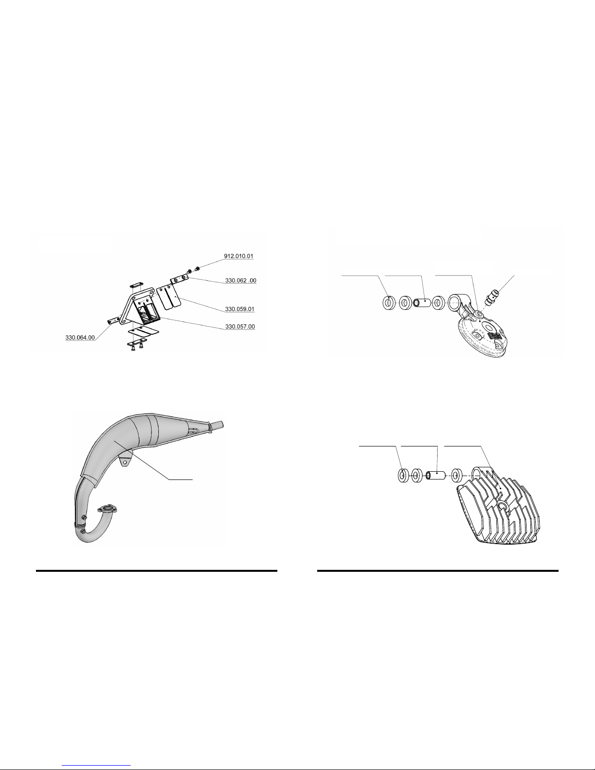
Diaphragm - complete
Exhaust R40 (RM9, RM14)
Head blast - water, air cooling
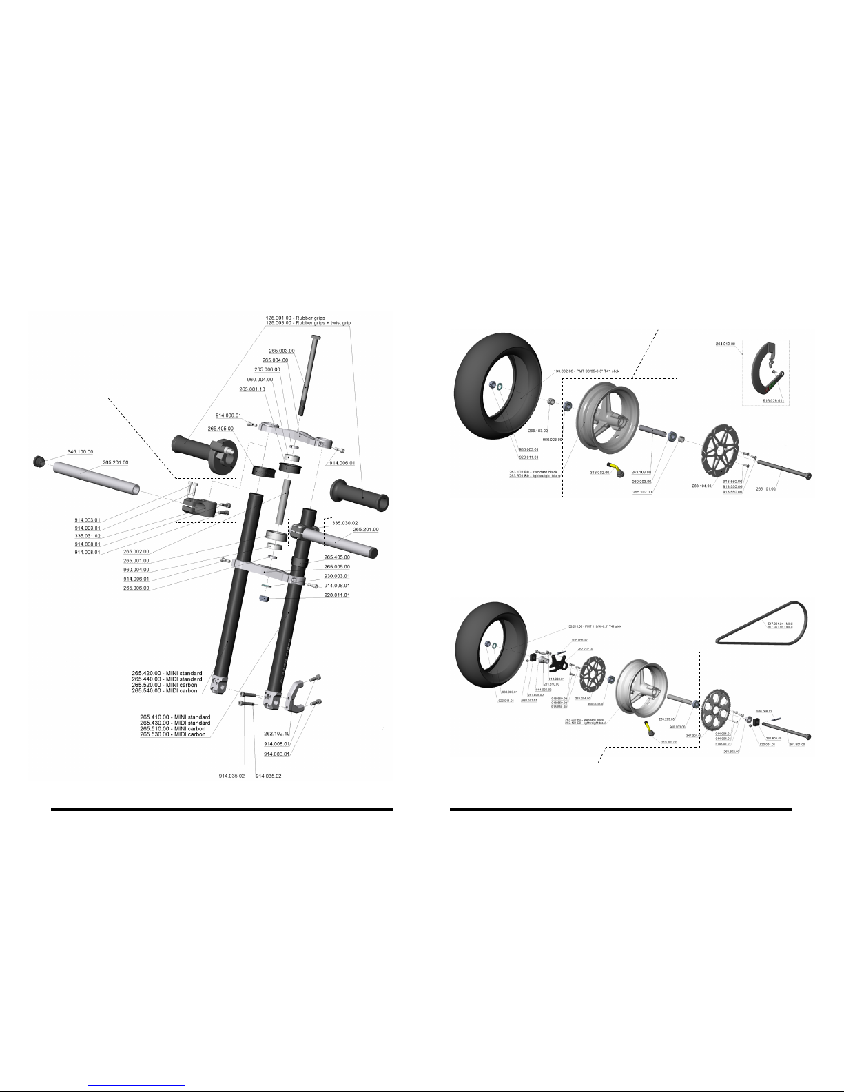
Front fork
Front wheel
Rear wheel
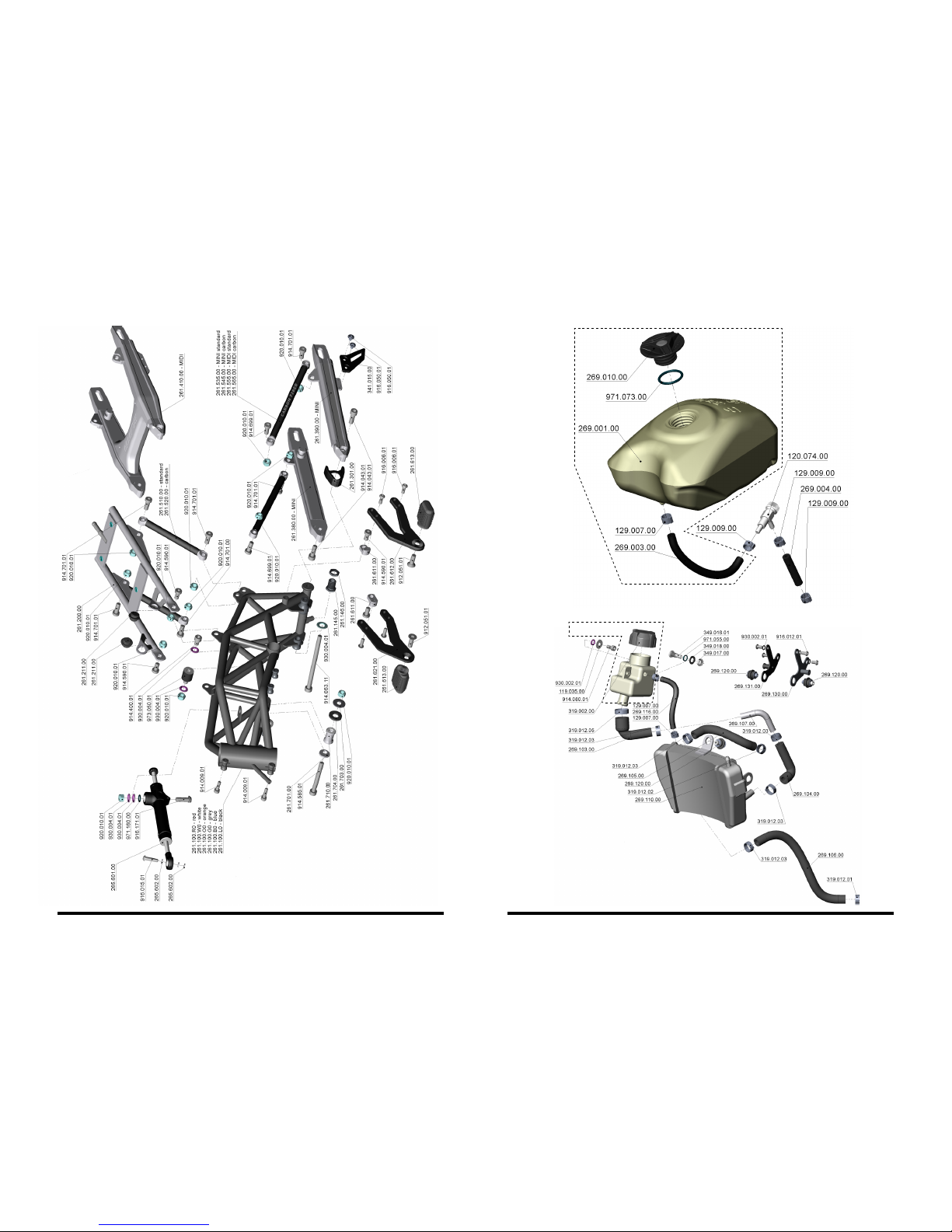
Frame
Tank - complete
Radiator
Exhaust - complete W40
Exhaust - complete W50
Exhaust silencer
Cowling
Cowling table
Identication information
INTRODUCTION
CONTENT CONTENT - SPARE PARTS
The Minibike - Ultima is designated for driving on enclosed tracks on at and dust free surfaces. Adults and also children can ride on it. Children can only ride on it under the supervi-
sion of a responsible adult. With its construction and equipment the minibike is designated
mainly for races on special tracks. The minibikes Blata are not designated to be used during
winter and under worsened climatic conditions. When the minibikes Blata are used during
winter and during worsened climatic conditions there occurs an increase of the mechanical
wear and tear of most of the product’s parts and corrosion of these parts, especially of the
groups that are exposed to the direct acting of the external effects. Besides this, the driver
exposes themselves to the danger of injury or permanent damage to health, especially while riding under worsened climatic conditions and mainly during winter.
The minibike is equipped with a single cylinder two-stroke gasoline engine, which is tted
with an air lter and an exhaust with a damper. The transfer of the driving torque from the
motor to the driven rear wheel is done by a chain drive, whose ratio can be modied in
small limits by the replacement of the sprocket wheels. Both of the minibike’s wheels are
tted with disc brakes. The rear brake is controlled by a lever on the left side and the front
brake is controlled by a lever on the right side of the handlebars.
1 2
Introduction
Technical data
Preparation of the minibike for operation
Safety warning
Before starting
Important warning
Starting
Riding
Regular maintenance
Maintenance and adjustment of the chain
Adjustment of engine bottom bracket
Bleeding the hydraulic brakes
Replacement of the brake pads of the hydraulic brakes
Adjustment of the mechanical brakes
Replacement of the front brake pads of the mechanical brakes
Replacement of the rear brake pads of the mechanical brakes
Removal and mounting of the front wheel
Removal and mounting of the rear wheel
Replacement of the pinion
Change of the geometry of the chassis
- change of the steering angle
- change of the seat height
- change of the foot pegs position
Replacement of the centrifugal clutch levers
Replacement of the tire
Removal and mounting of the air lter
Adjustment of the centrifugal clutch
Maintenance of the cooling system
Tightening torques
Composite materials
Noise
Declaration about noise
Putting out of operation
Storage
Repeat putting into operation
Permanent putting out of operation
Technical service
2
3 - 4
5
5
5
6
6
6
7
7
8
9
11
11
12
12
13
14
14
15
15
17
18
19
19
19
20
21
22
23
24
24
25
25
25
25
25
27
27
28
28
29
29
30
30
31 - 32
33 - 34
35 - 36
37
37
38
38
39
39
40
41
42
42
43
44
44
45
45
46
47 - 48
49 - 50
51
Page 5

TECHNICAL DATA
engine (Blata 2T) RM9 RM14 R40 W40 W50
cooling air air air water water
displacement (cm3) 39,8 39,8 39,8 39,8 49,7
power (kW) 3,3 5,9 7,5 10,7 12
torque (Nm) 3,5 4,8 7,2 8,6 10,7
carburetor DELL´ORTO PHVA 14 DELL´ORTO PHVA 14 DELL´ORTO PHVA 14 DELL´ORTO PHVB 19 DELL´ORTO PHVB 19
ignition contactless contactless contactless contactless contactless
starting manual manual manual manual manual
clutch automatic centrifugal automatic centrifugal automatic centrifugal automatic centrifugal automatic centrifugal
frame steel tube frame, rear fork is made of dural (*), under seat frame is made of dural (*), front fork is steel or dural-composite
front brake disk, hydraulic or mechanical
rear brake disk, hydraulic or mechanical
front wheel dural 2,1´´ x 6,5´´ - 99
rear wheel dural 2,3´´ x 6,5´´ - 130
front tire 90 / 65 - 6,5´´
rear tire 110 / 50 - 6,5´´ or 90 / 65 - 6,5´´
fuel 33 : 1 (gasoline 95 - 98 octane: 2T synthetic oil)
fuel tank volume 1,4 litres
weight 18,3 - 20,5 kg (in relation to equipment)
carrying capacity max 100 kg
dimensions L x W x H (mm) MINI 915 x 550 x 525, MIDI 995 x 550 x 550
* optional with composite elements
3 4
Page 6
PREPARATION OF THE MINIBIKE FOR OPERATION
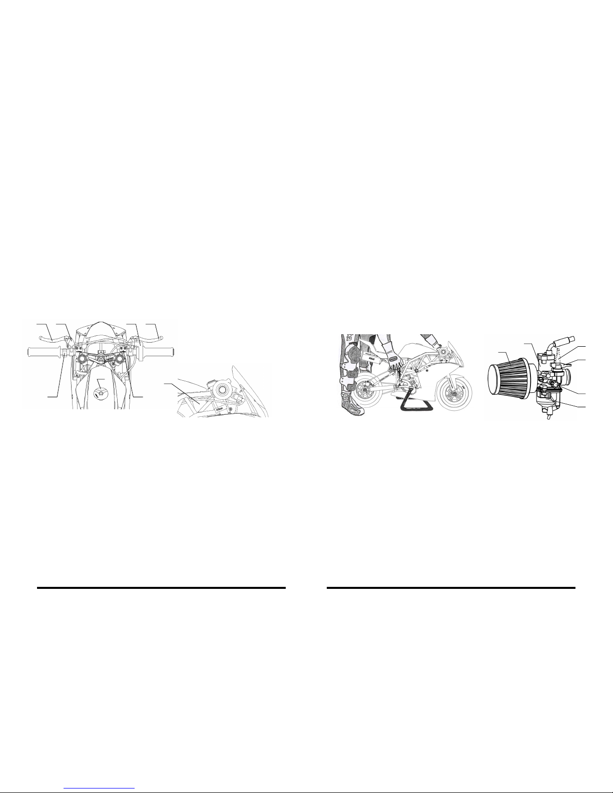
The Minibike is delivered packaged in a carton box with folded handlebars and brake
levers. After unpacking, set the handlebars to the functioning position which suits
you best. When turning all the way the brake levers must not come into contact with
the fairing. After setting it up tighten the screws of the handle bar clamps (1), the bra-
ke lever screws (2) and the throttle handle screws (3) see g. 1. Verify the smooth and
free movement of the throttle control cable and both of the brake hoses / cables.
Check that the cooling system is lled with uid - in the leveling reservoir (7) the uid
must be up to 1 volume. In case of lling up the uid, perform the air venting (procedure according to chap. MAINTENANCE OF THE COOLING SYSTEM). Fill the tank
with fuel.
6
1
3
B
4
A
2
32 5
7
8
4
1
SAFETY WARNING
This vehicle does not totally conform to the regulation of the MD (Ministry of Trans-
portation) no. 341/2002 Coll. and it is not permitted for operation on public communications. Careless operation of this machine can result in serious injuries. The rider
can decrease these eventual risks to a minimum by wearing safety equipment. The
safety helmet must be properly worn (covering the ears - mainly for children), eye
protection, protective gloves, elbow and knee protectors and suitable footwear. Do
not use this vehicle on an icy or oily surface. Avoid uneven surfaces and obstacles.
Always hold the handlebars with both hands.
BEFORE STARTING
For the service life of the engine and for its power it is necessary for the minibike to
be properly run in. The motorbike is considered as being run in after the consumption
of a volume of ve full fuel tanks. For running in use the gasoline 95 - 98 octane with
synthetic oil for two-stroke motors (2T) in a ratio of 30 : 1, after the run in use a ratio of
33 : 1. Thoroughly mix the mixture of fuel and oil before pouring it into the tank! During the run in period do not spin the motor to the maximum revolutions and do not let
the motor overheat. Check the tire air pressure - 200 kPa (2 bars), which can be modied according to the weight of the rider. The pressure in one tire must not exceed 250
kPa (2.5 bars) on the front and also the rear wheel.
IMPORTANT WARNING
STARTING
RIDING
Turn the engine off immediately if the level of the cooling uid in the leveling reservoir
increases during operation! Check the drive of the cooling pump and the cooling system
for leaks. After this inspection perform an air venting. The increased level of the cooling
uid is a sign of an overheated motor and the piston can get seized in the cylinder.
Perform the starting only up on the stand - see g. 2. Fill the minibike tank with fuel
and close it by screwing on the cap. Open the fuel supply valve. Move the choke lever
from the position “A” to the position “B” g. 3 and pull the starting cord twice without
turning the throttle handle. You will start up the engine with the next quick pull. After
the engine has been running for a while, move the choke lever back to the position
“A”. Leave the motorbike on the stand with the engine running and if it is necessary
then adjust the engine revolutions to a level where the clutch does not drive the rear
wheel. Perform the adjustment by the screw (3) on the carburetor g. 3.
After sitting on the minibike and turning the throttle handle we start to ride. Before
braking decrease the fuel using the rotary handle and using the left-hand rst lightly
squeeze the rear wheel brake lever and then use the right hand to squeeze the front
brake lever. During this pay attention so that the wheels do not go into a slide. The
minibike engine is turned off by pressing the red button of the switch on the handle-
bars. AFTER THE FIRST RIDE IT IS NECESSARY TO INSPECT THE TIGHTNESS OF
THE BOLTS AND NUTS, ESPECIALLY OF THE ENGINE AND THE CHASSIS PARTS.
Re-inspect the effectiveness and the adjustment to the breaks.
Control elements:
1. Handle bar clamp screws
2. Brake lever screws
3. Throttle handle screws
4. Stop switch
5. Front brake lever
6. Rear brake lever
7. reservoir - cooling uid
8. Fuel tank lid
Carburetor (applies to carburetor
PHVA 14, PHVB 19):
1. Air lter
2. Body of the carburetor
3. Adjustment screw for idle running
4. Float chamber
A - Choke lever position for riding
B - Choke lever position for cold starts
g. 1
g. 2 g. 3
5 6
Page 7
REGULAR MAINTENANCE
MAINTENANCE AND ADJUSTMENT OF THE CHAIN
Regular performing of maintenance is one of the best methods of contributing to the
prolonging of the service life of the machine, ride safety and the lowering of expenses.
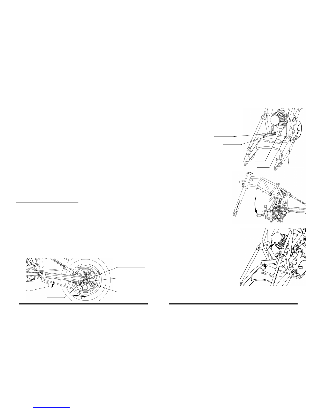
Loosen the rear wheel axle and the check nuts of the adjustment bolts. Adjust the
recommended slack of the chain to 5 mm, by even tightening / loosening of the adjustment bolts on both sides. Tighten the wheel axle. Tighten the check nuts of the
adjustment bolts against the movable blocks. It is suitable to measure the given measurement (x) using a slide gauge (it must be the same on both sides of the fork).
The chain must be regularly lubricated which increases its service life and decreases
the operational noise. The chain must be lubricated every time after riding on a wet
road. We recommend to lubricate it with a special oil in a spray. If it is necessary to
replace the chain then also inspect both of the sprocket-wheels. If they are worn then
they must be replaced with the chain at the same time.
A - Before each ride:
- Inspect the cables / hoses and the effectiveness of the breaks.
- Inspect the lubrication and the adjustment of the chain drive. The chain should
have a slack of 5 mm.
- Always clean the minibike and maintain it in a clean state after every use.
Do not use aggressive cleaning products.
- After 1 hour of riding always wash the air lter in gasoline and smear oil on to it for
air lters. The same applies after every ride in the rain.
- After 1 hour of riding clean the clutch with compressed air and perform an inspe ction of the adjustment of the clutch levers.
- Inspect the condition of the brake pads. The lining thickness cannot be less than 1 mm.
Perform the basic adjustment of the brakes.
- Inspect the cooling system for leaks and the amount of the cooling liquid in the
leveling reservoir - must be 1/2 the volume of the reservoir.
- Inspect the condition of the clutch lining - its thickness cannot be less than 1 mm!
Perform an adjustment of the clutch levers.
- Make a visual inspection of the entire minibike. Replace all the damaged parts
(worn, deformed) with new ones.
- Inspect the tires’ air pressure.
- Inspect the tightness of all the bolts and nuts - see the tightening torques table.
B - Always following 5 hours of operation:
- Thoroughly clean the oat chamber of the carburetor.
g. 4
rear wheel shaft
adjustment bolt
movable block
check nuts
5 mm
x
7 8
ADJUSTMENT OF ENGINE BOTTOM BRACKET
The above-described adjustment of the lower bracket of the engine perform at each
dismantling the engine or engine replacement. To ensure stop screw, locking nut
and screw is recommended to use glue thread.
1. Remove the engine braket on cylinder
head and keep the engine on t he bot tom bracket only.
2. Loosen the screw M8x120 in the engi ne bottom bracket (keep screwed).
3. Turn the engine in the bot tom bracket
utmost down. H erewith you will make
space for work with spanners, g. 6.
Loosen the lock nut and stop screw.
4. Using a set of keys on the bottom
bracket of the engine No.: 269. 440.00
torque rst stop screw against the
engine and then tighten the lock nut
to lock against the eye frames, g. 7.
5. Turn t he e ng in e b ac k to its ori gi na l
position and mount bracket to cylin der head.
6. Tig hte n t h e sc rew M 8 x12 0 on th e
bottom engine mount.
g. 6
g. 7
1.
2.
g. 5
Locking nut
Stop screw
Engine
Washer
Screw
M8 x 120
Page 8
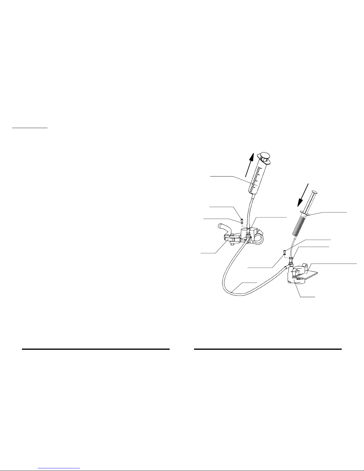
BLEEDING THE HYDRAULIC BRAKES
important warning:
- The brakes are one of the most important components of your minibike. We recom mend to leave the maintenance and the adjustment of the hydraulic brakes up to a
qualied mechanic.
- Follow the safety warning.
- Use only the brake uid DOT4.
- When working with the brake uid make sure to prevent it coming into contact with
other parts of the brakes and other parts of the minibike. Primarily protect the brake
pads and the brake discs.
For bleeding the hydraulic brakes we recommend to use the Bleeding set (or. no.
262.900.00). The procedure is the same for the front and the rear brake. Remove the
hydraulic brake from the minibike. In to the caliper, between the brake pads, we insert
the brake disc or a metal plate of the same thickness. Place the brake into the position
as illustrated in the picture no. 8 - ow-through bolts at the caliper and also the lever
are pointing upwards, the brake lever is higher than the caliper.
Brake uid may escape in the area around the ow-through bolts. We recommend
wrapping the ow-through bolts with an absorbing material before performing the
bleeding. Remove the bleeder plugs (wrench TX10) from the ow-through bolts on the
caliper and the lever and remove the bleeder plug O-ring seals. Place the hoses with
the reduction for the M5 thread on to the sprayers from the bleeding set. Fill one spra-
yer with brake uid – approx. 20 ml. Screw this sprayer into the ow-through bolt on
the brake caliper. Leave the second sprayer empty and screw it into the ow-through
bolt in the lever. With gentle pressure, start to push the brake uid from the full spra-
yer to the empty one. The pushing through of the entire volume of 20 ml should take
at least 20 seconds. Do not push out the full sprayer completely, but stop the pushing
through at least 5 mm before reaching the bottom. Too quick of a pushing through
of the uid may cause damage to the parts inside the brake. After pushing through
the entire volume, rst unscrew the sprayer on the side of the lever and screw in the
bleeder plug with the O-ring. Then unscrew the sprayer on the side of the caliper and
screw in the bleeder plug with the O-ring. Clean any spilled brake uid off of the brakes and mount them back on the minibike. Verify the proper function of the brakes
before riding.
g. 8
compensation for the disc
bleeder plug
bleeder plug
O-ring seal
bleeder plugs
bleeding set
262.900.00
bleeding set
262.900.00
O-ring seal
bleeder plugs
ow-through bolt
ow-through bolt
caliper
lever
hose
0 ml
20 ml
min. 20 seconds
9 10
Page 9
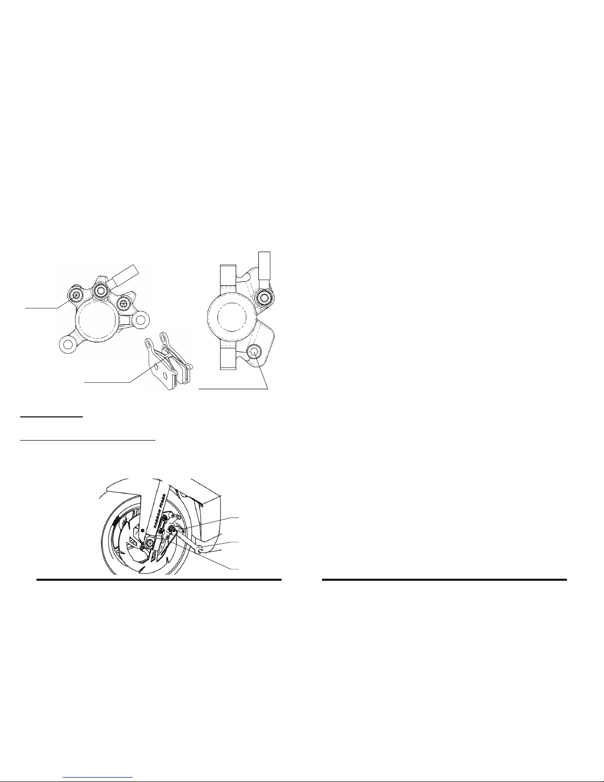
General adjustment:
The general adjustment of the mechanical brakes is performed by the adjustment
mechanism of the brake levers on the handlebars.
Basic adjustment of the mechanical brakes:
Put the adjustment mechanism on the brake lever to the initial position. Loosen the
nut (1) and screw in the adjustment bolt (2) so that the wheel does not turn. Return the
bolt (2) back by 1/4 to 1/2 a turn and tighten the locking nut (1). Do not use the cable
catch (3) for adjusting the brakes!
REPLACEMENT OF THE BRAKE PADS OF THE HYDRAULIC BRAKES
ADJUSTMENT OF THE MECHANICAL BRAKES
Loosen the lock ring of the bolt of the brake pads. Unscrew the bolt of the brake pads.
Remove the worn pads from the caliper together with the metal spring of the brake
pads. Place the metal spring between the pair of new pads and place the set into the
caliper. The tongues on the brake pads must t into the shape in the brake caliper.
Screw in the bolt for the brake pads (must pass through the openings in the brake
pads) and secure it with the lock ring.
g. 9 g. 10
g. 11
2
1
3
bolt for the brake pads
metal spring
for brake pads
bolt for the
brake pads
front brakerear brake
REPLACEMENT OF THE FRONT BRAKE PADS
OF THE MECHANICAL BRAKES, g. 30
REPLACEMENT OF THE REAR BRAKE PADS
OF THE MECHANICAL BRAKES, g. 31
First screw in the adjustment mechanism of the right brake lever (122.002.00) to the
initial position on the handlebars. Loosen the nut (332.020.00) and unscrew the adjustment bolt (916.065.02) so that during the squeezing of the front brake lever the
cam lever (312.017.00) is above the head of the bolt M5 (312.018.00), which secures
the brake pads and the pads spring (312.020.00). Unscrew this bolt and replace the
worn brake pads with new ones. During assembly, carefully place the pads spring, so
that both of the pads are pushed in the direction towards the front stop. During the
replacement of the pads do not loosen the bolts M5 (914.001.01) on the guide pins and
do not loosen the cable catch!
First screw in the adjustment mechanism of the left brake lever (122.001.00) to the initial position on the handlebars. Loosen the nut (332.020.00) and unscrew the adjustment bolt (916.065.02) all the way to the end. Unscrew the nut M10 (920.011.01) of the
rear axle, slide it out and remove the rear wheel from the fork. Slide the brake off of the
guide pins, which releases the brake pads, and replace them with new ones. During
the replacement of the pads do not loosen the bolts M5 (914.001.01) on the guide pins
and do not loosen the cable catch! During assembly proceed in the reverse manner
and then perform the adjustment and the basic adjustment of the brake.
11 12
Page 10
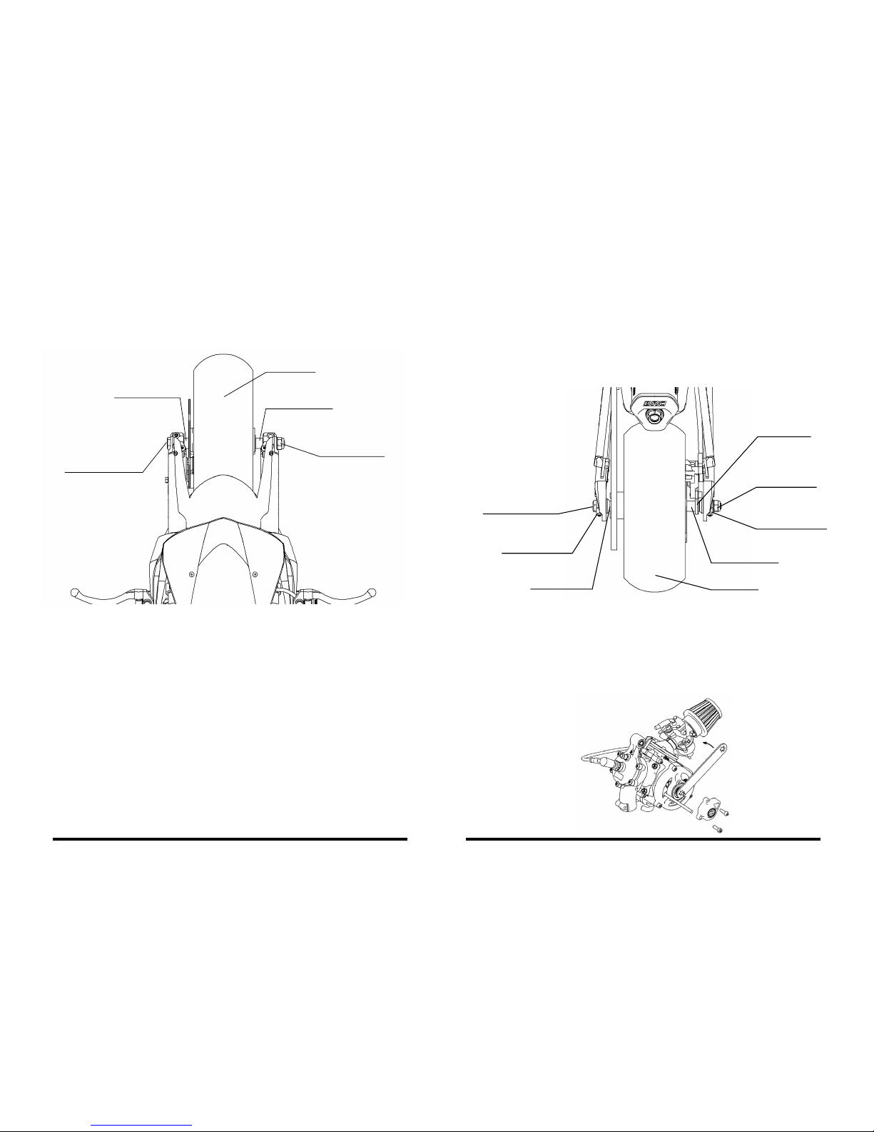
REMOVAL AND MOUNTING OF THE FRONT WHEEL
REPLACEMENT OF THE PINION
REMOVAL AND MOUNTING OF THE REAR WHEEL
Unscrew the nut of the front wheel axle and slide the axle out. Remove the wheel
carefully from the fork in the downward and forward direction. During assembly it is
necessary to pay attention to the correct placement of the spacers between the wheel
and the end piece of the front fork. The length of the spacer is different for the right
and the left side.
First remove the bearing housing on the left side of the motor. Loosen the nut of the
rear wheel axle and the chain tensioner bolts and take the chain off of the pinion. Carefully slide a steel rod or a screwdriver into the opening of the clutch drum g. 14, so
that the clutch drum is prevented from turning during the loosening of the pinion. Use
a special wrench (319.050.00) to loosen the pinion by turning counterclockwise. The
assembly of the new pinion is performed in the reverse procedure.
Loosen the nut of the rear wheel axle. Loosen the check nuts and the adjustment bolts
on the movable blocks. Move the wheel forward in the rear fork end piece and remove the
chain off of the sprocket. Slide out the rear wheel axle and carefully remove the rear brake
caliper from the disc. When mounting the rear wheel back it is necessary to pay attention
to the correct placement of the spacers. The spacers are different for the right and the left
side. Place the rear brake caliper holder on to the right spacer and continue in the reverse
procedure. After the mounting of the rear wheel perform an adjustment of the chain.
front wheel
rear wheel
right spacer
left spacer
movable block
rear wheel shaft
movable block
rear wheel
axle nut
rear brake
caliper holder
right spacer
left spacer
axle of front wheel
axle nut of
front wheel
g. 12
g. 13
g. 14
13 14
Page 11
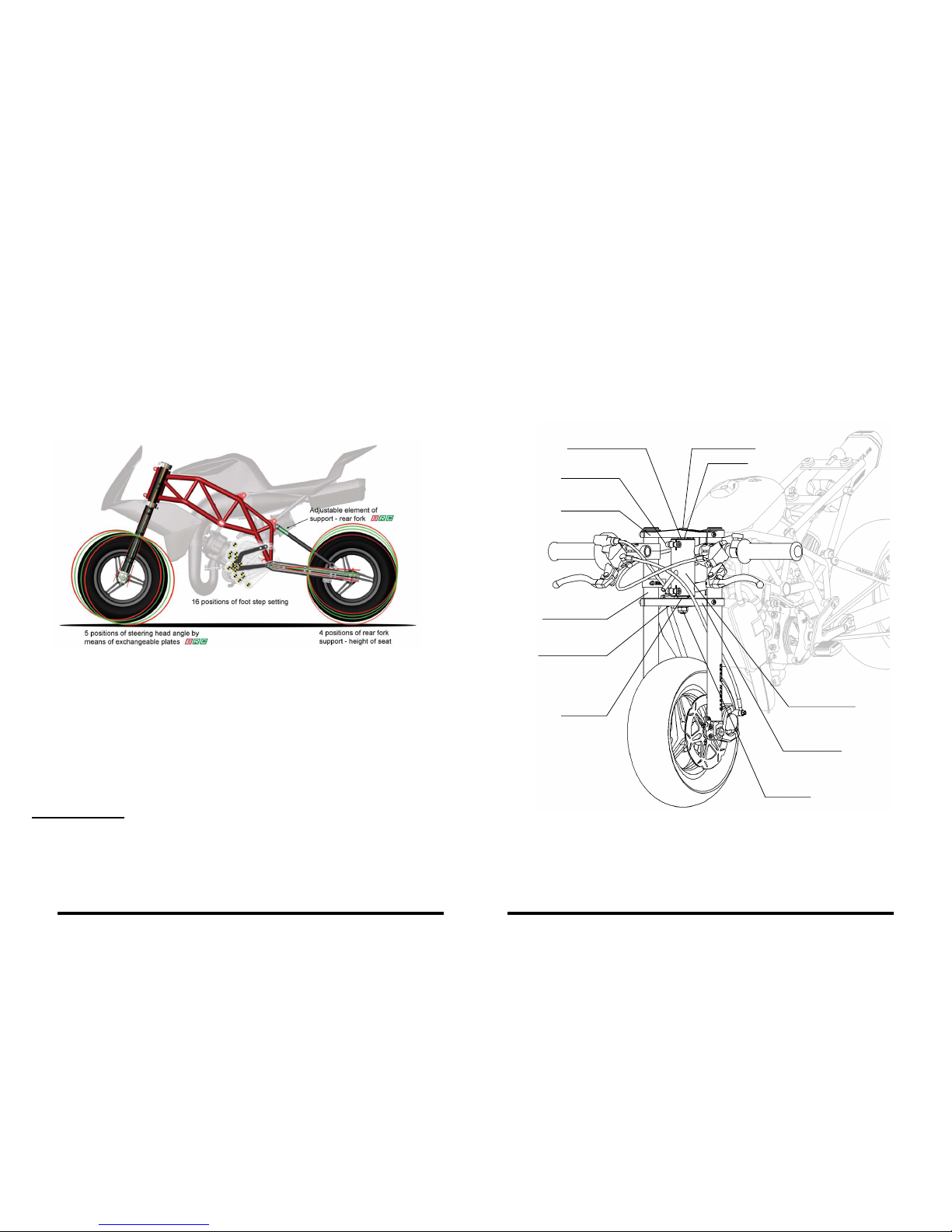
CHANGE OF THE GEOMETRY OF THE CHASSIS
Change of the steering angle
The BLATA SET-UP SYSTEM includes three areas of the minibike, in which it is possi-
ble to signicantly change the geometry of the chassis. This is the change of the
steering angle using exchangable steering plates, the change of the seat height using
adjustable rear fork supports and the change of the foot rests’ position.
Suitable adjustment of the geometry of the chassis, according to the demands of the
rider and the track characteristics, signicantly improves the control of the minibike
and moves the limits of possibilities during the ride. Following any modication to the
geometry of the chassis pay extra attention during the rst ride, because the minibike
will act in a different manner than what you‘re used to.
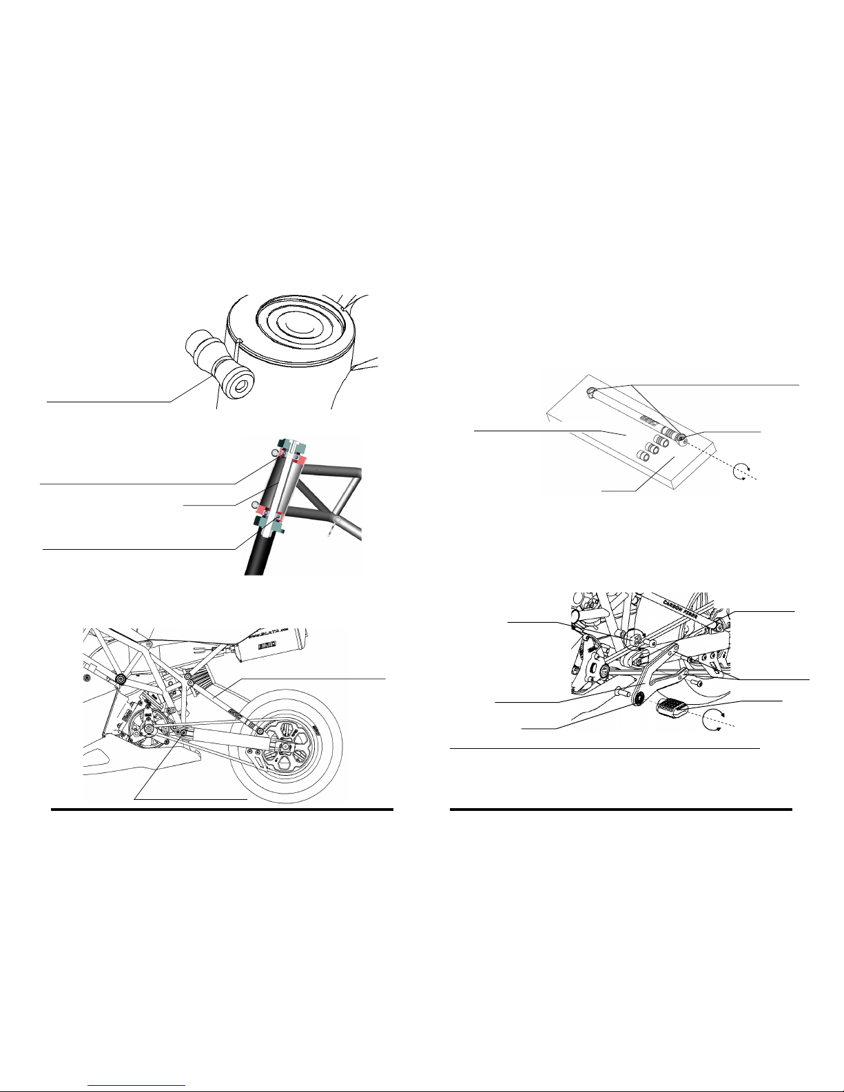
The change is possible by exchangable steering plates, which enable to change the
steering angle by values of ±2° to ±4°.
Perform the replacement of the plates in the following manner with the cowling removed.
Remove the steering shock absorber bolt on the bottom holder of the front fork. Loosen the
steering axle nut under the bottom fork holder. Slide out the steering axle. Remove the entire loosened front fork set from the steering neck in the forward direction (we recommend
to have another person assisting, which will be holding this set during the course of the
next steps). Loosen the bolts in the clamps on the steering neck. Slide a rod with a diameter of 6 mm through the steering neck and carefully knock out one plate with the bearing.
Remove the spacer tube and knock out the second plate from the other side.
important warning:
- Always mount the steering plates on to the minibike in a pair with the same
angle difference (same color).
- Always position the steering plates so that the groove in the steering plate
lies on the groove in the steering neck on the frame g. 17.
- The plates in the steering neck must always be positioned against each other (for
example the top plate with bearing in front, the bottom plate with bearing in
the rear) g. 18.
g. 15
Carefully tap in the required steering plate into one end of the steering neck. Insert the
spacer tube and tap in the second plate from the other side of the steering neck. Pay
attention to the proper positioning of the plates, as it is described above. Place the
front fork set onto the steering neck. Insert spacers between the upper holder of the
fork and the upper plate and between the lower holder of the fork and the lower plate.
Draw the set together with the steering axle and tighten the bolts in the clamps on the
steering neck. Attach the steering shock absorber to the bottom holder of the fork.
set
front fork
steering shock
absorber bolt
spacer
steering
axle nut
bottom holder
of the fork
upper holder
steering neck
clamp
steering plate steering axle
spacer
steering neck
g. 16
15 16
Page 12
the groove in the plate
lies on the groove in the neck
g. 17
g. 18
upper plate - bearing in the front (in the rear)
lower plate - bearing in the rear (in the front)
spacer tube
The change is possible using the adjustable supports of the rear fork, which enable to
change the height of the seat in the range of approx. 3.5 cm.
Current information on available options and components to change the height of the
saddle, contact your dealer.
Change of the seat height
adjustable supports of the rear fork
main bolt of the rear fork
g. 19
The adjustment is performed by the replacement of the spacer rollers of various lengths on the disassembled supports of the rear fork. We follow the following procedure
during the replacement. Remove both the supports of the rear fork from the minibike.
Totally unscrew the securing bolts from the supports. Replace the spacer rollers with
others (just by sliding on). Always use the same length rollers (marked by groups) on
both of the supports. Place the assembled support with the seating areas of the end
pieces on to a at pad, screw in and tighten the securing bolt. Loosen the main bolts
on both sides in the front part of the rear fork. Mount the supports onto the minibike
and tighten the main bolts on the rear fork.
It is possible to achieve sixteen various positions of the foot rests, using the combination of 4 holes in the foot rest holders, the rotary cam and two holes in the front end
piece of the rear fork. The suitable angle of the foot rest can be adjusted by turning the
foot rest in the spline, through which it is attached to the foot rest holder.
important warning regarding the change of the geometry of the chassis:
With regards to the fact that the change of the geometry of the chassis results in the
change of the spatial arrangement of a signicant amount of parts, always check, following the performing of the change of the geometry of the chassis, whether any collision is occurring between the parts (radiator X front wheel , cowling X brake lever, intake
lter X rear wheel, cowling X front wheel, steering shock absorber X radiator etc.)
Change of the foot rests position
seating areas of the end pieces – parallel!
at pad
spline
foot rest holder
rotary cam
2 holes in the front end
piece rear fork
4 holes in the
foot rest holders
foot rest
spacer roller of various lengths
securing bolt
g. 20
g. 21
proper setting of the steering plate
in the steering neck
example of the correct positioning of
the steering plates against each other
17 18
Page 13
REPLACEMENT OF THE CENTRIFUGAL CLUTCH LEVERS
REPLACEMENT OF THE TIRE
REMOVAL AND MOUNTING OF THE AIR FILTER
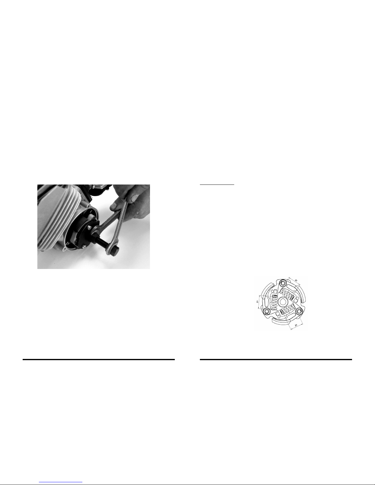
Loosen the chain, remove the bearing housing and take the chain off the pinion. Unscrew the 3 bolts holding the clutch housing together with the clutch basket and remove
the clutch housing. Loosen the nut of the catch driver by placing a pipe between the
engine block and the catch driver and then loosen the nut. Use the puller puller MP-1
(159.019.00) to remove the clutch set from the motor g. 22. Unscrew the adjustment
bolts of the springs and remove the lock rings from the pegs. Then replace the clutch
levers with new ones. We recommend to also replace the springs. During assembly,
rst place on the spring with the cup onto the lever and mount them together so that the
spring cup is pushed against the catch driver and place the lever onto the peg. Secure
it by the lock ring and mount the adjustment bolts. Perform the basic adjustment accor-
ding to chap. ADJUSTMENT OF THE CENTRIFUGAL CLUTCH page 18.
First remove the wheel from the minibike. For the front wheel unscrew the brake disc,
and for the rear wheel unscrew the brake disc and the sprocket-wheel. Release the
air from the tires, preferably by unscrewing the valve out. Place the wheel on a solid
pad and push the tire bead from the edge of the rim towards the middle of the rim’s
span area. Use one assembly lever to slip the tire bead, at the valve, across the edge
of the rim and hold it there. Insert another assembly lever right beside and slip over
the remaining part of the tire across the edge of the rim.
Place the second tire bead into the middle of the rim’s span areas and slip it across
the edge of the rim without using assembly levers. Perform the mounting in the reverse procedure. The assembling of the tire onto the rim is always started on the opposi-
te side of the valve. Perform the air inating of the tire according to the weight of the
rider, with a maximum of 250 kPa (2.5 bars) and mount the wheel into the minibike.
During the removal of the lter, rst loosen the screws of the strap, which is securing
the rubber extension of the lter on the carburetor. This will release the lter, which is
then removed and carefully washed in gasoline and smeared with oil for air lters and
is mounted using reverse procedure.
g. 22
ADJUSTMENT OF THE CENTRIFUGAL CLUTCH
After the rst hour of riding perform the inspection of the adjustment of the clutch
jaws. The clutch should engage at 8000 - 8 500 RPM according to the weight of the
rider. Adjust it to the higher prescribed revolutions when the rider is of the heavier
weight.
basic adjustment:
The basis for the adjustment is the length of the spring, which is measured from the
seating area on the clutch lever to the spring cup g. 23. For a new clutch (following
the replacement of the clutch lining) and with a clutch drum with an inside diameter
of 80 mm, set this length to 21.00 mm. During this setting the clutch starts to grab at
8000 RPM. The grabbing RPM increase as a result of the operational wear of the clutch
lining and the drum. Therefore continually inspect the grabbing RPM (inspection after
every ride) and loosen or possibly tighten the adjustment bolts, in order to maintain
the grabbing RPM at a value of 7000 - 9000 RPM. The tightening of the adjustment
bolts increases the grabbing RPM and loosening them decreases the grabbing RPM.
The grabbing RPM can differ in relation to the power of the motor, the weight of the
rider and the character of the track. In no case may the clutch continue to further slip
after gripping (during higher RPM than the gripping RPM). This would result in a quick
wearing of the clutch lining and possibly also in irreversible damage to the entire
clutch. Pay attention to always set all the springs evenly, to prevent uneven wear of
the clutch lining. Every time following the replacement of the clutch levers there must
be performed the basic adjustment of the clutch springs to the measurement of 21.00
mm and 8000 RPM. For the setting of the gripping RPM of the centrifugal clutch, we
recommend to use an RPM gauge connected to the high voltage spark plug cable.
g. 23
19 20
Page 14
MAINTENANCE OF THE COOLING SYSTEM
1. Filling up with uid:
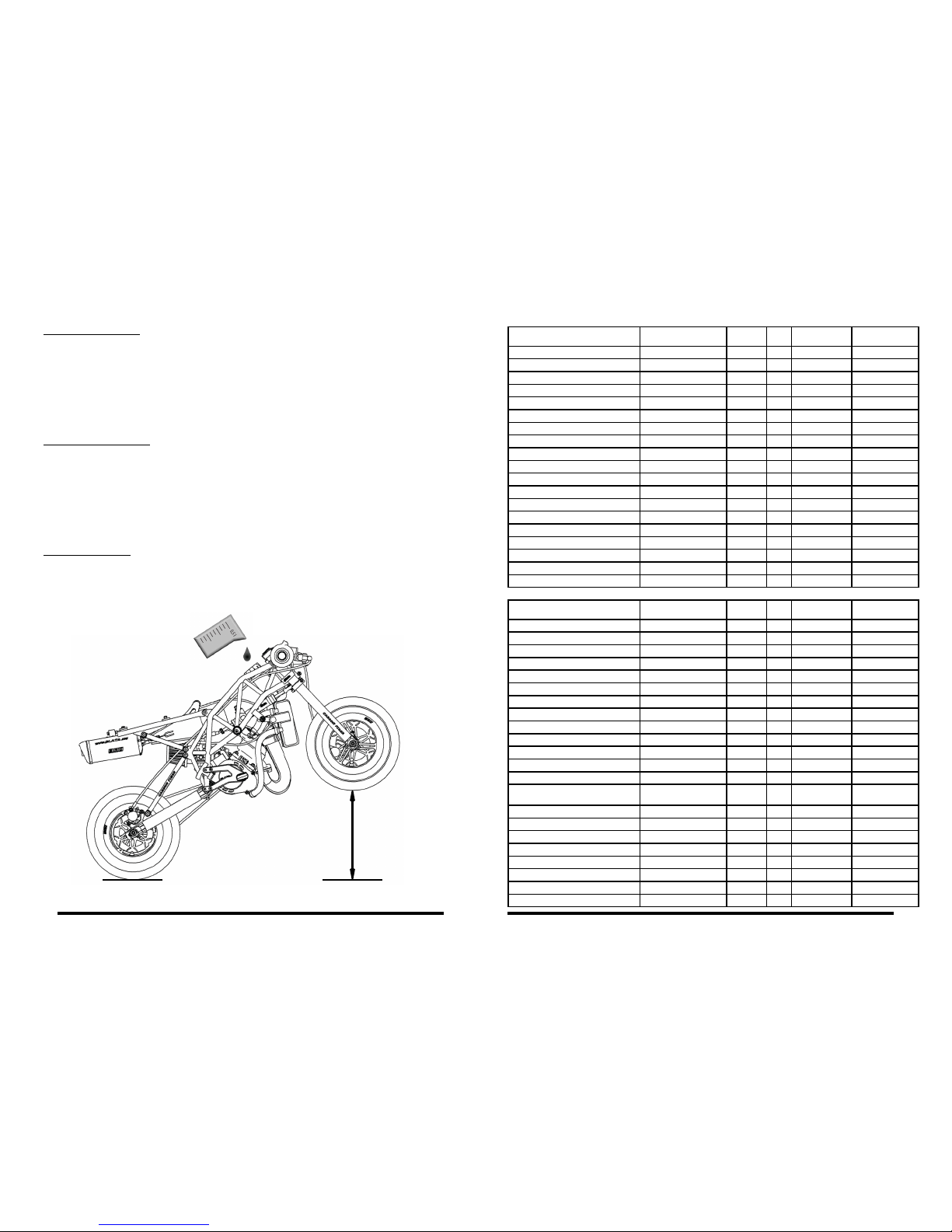
Remove the top cowling. Place the minibike so that the front wheel is 30 cm higher
than the rear wheel, see g. 24. Remove the cap from the leveling reservoir and
loosen the bleeding bolt M5 by 6 turns, which is located in the upper left part of the
radiator.Slowly pour the cooling liquid into the leveling reservoir. The cooling uid
volume in the system is 0.5 l. Close the reservoir and the bleeding bolts. Place the
minibike onto the stand and start it up, leave it running for about 1 minute. Then
again place a support under the front wheel and use the bleeding screw to perform
the additional bleeding. Hereby the minibike is prepared for operation.
2. Checking the cooling:
Check the amount of the uid in the leveling reservoir before every ride! After 10
hours of operation, remove the starting cover and check the condition of the cog
belt which drives the cooling uid pump.
Important warning: turn off the engine immediately if the cooling uid level rises in
the leveling reservoir during operation! Check the drive of the cooling pump and the
cooling system for leaks. After this inspection perform an air venting. The increased
level of the cooling uid is a sign of an overheated motor and the piston can get
seized in the cylinder!
3. Draining the uid:
Drain the uid by removing the hose on the bottom part of the engine. Unscrew the
cap of the leveling reservoir during the draining. Drain the uid into a container that
is prepared ahead of time and ensure the ecological liquidation of the uid.
g. 24
30 cm
TIGHTENING TORQUES
21 22
use - MOTOR number g. pc
tightening
torque (Nm)
securing
Cylinder head, water – M6 920.015.01 35, 36 5 10
Cylinder bolt – M6 920.015.01 35, 36 4 9,5
Intake ange – M5 914.003.01 34, 35, 36 4 5
Starter housing – M6 914.008.01 34, 35, 36 3 10,5
Ratchet bolt – M6 916.012.01 38 1 9 thread glue
Rotor nut – M10 920.021.01 34, 35, 36 1 25
Starter levers’ bolts – M5 916.051.01 37 2 5,5 thread glue
Coil bolts – M5 914.026.01, 914.003.01 34, 35, 36 2 5,5
Coil holder bolt – M6 914.510.01 34, 35, 36 1 8
Engine block bolts – M6 914.035.01 34, 35, 36 5 12
Clutch catch driver nut – M8 920.020.01 34, 35, 36 1 22 thread glue
Clutch housing bolts – M6 914.008.01 34, 35, 36 3 10,5
Bearing housing bolts – M6 914.001.01 39 2 10,5
Pump axle nut – M6 920.009.01 34, 35, 36 1 8 self-locking
Membranes bolts – M3 912.010.01 41 4 0,8 thread glue
Float chamber bolts – M4 carburettor - 2 2
Slider cover bolts – M4 carburettor - 2 2
Fuel strainer cover bolt – M5 carburettor - 1 2,5
Pinion – M8 330.029.00 39 1 22 thread glue
used - FRAME number pc
tightening
torque (Nm)
securing
Axle nut for front wheel – M10 920.011.01 45 1 35 self-locking
Brake disc front – M5 918.550.00 46 3 15
Front brake holder – M6 914.035.02, 914.008.01 45 4 12,5 thread glue
Steering axle – M10 920.011.01 45 1 20 self-locking
Handlebar clamp – M6 + M5 914.003.01, 914.008.01 45 2 + 2 9,5
Fork holders – M5 914.006.01 45 4 9
Engine holders, head – M8 920.010.01 48 1 18,5 self-locking
Engine holders, bottom – M8 914.063.11 48 1 22 thread glue
Axle nut for rear wheel – M10 920.011.01 47 1 35 self-locking
Brake disc, rear – M5 918.550.00 47 3 15
Sprocket-wheel – M5 914.001.01 47 3 15
Cover for sprocket-wheel – M5 916.050.01 48 2 10
Bolt – M3 916.179.02 53 2 2,5
Bolts of the fairing, seat
916.005.01, 916.014.01
916.415.01
55 5 6
Clamps for the handlebar levers – M6 brakes - 2 7,5
Brake levers in a clamp – M5 brakes - 2 3,5
Throttle handle clamp – M5 throttle grip - 2 5
Throttle handle cap – M4 throttle grip - 2 2
Reservoir holder – M6 914.080.01 50 1 6
Front fender – M5 918.900.01 55 4 5,5
Rear forks – M8 914.043.01 48 2 22 self-locking
Under-seat frame – M8 920.010.01 48 10 15 self-locking
Page 15
COMPOSITE MATERIALS
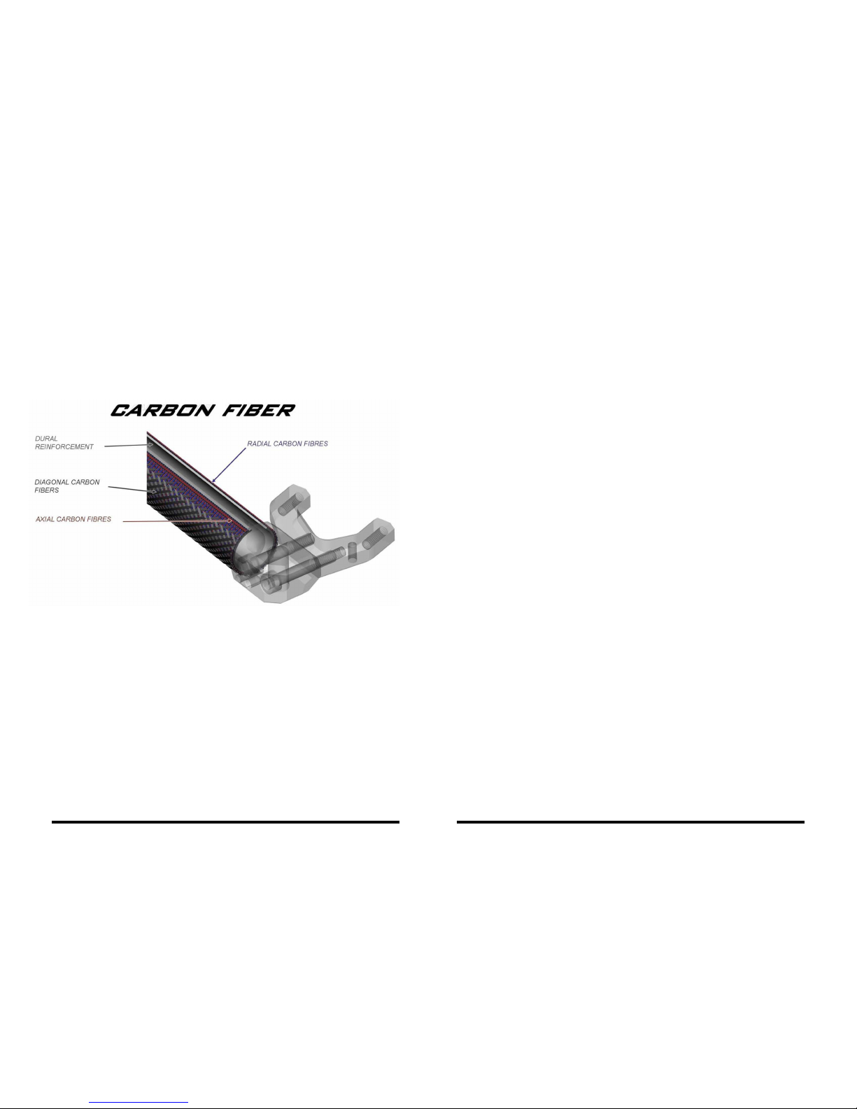
The company Blata is the rst among minibike manufacturers to bring modern com-
posite materials. The Minibike Ultima uses carbon not only as a fashion supplement,
but as a fully functional material, which exceeds the characteristics of classic metal
materials. Composite materials bring not only an uncompromising lowering of weight,
but also radical rigidity and excellent damping characteristics. You will immediately
recognize the positive difference in the riding characteristics during the rst ride on
a minibike which is tted with such components. The carbon front fork, the supports
for the under-seat frame and the supports for the rear forks are manufactured using
the unique patented technology of axial ber winding.
The Minibike Ultima is also t-
ted with other composite components. The cap for the starting
and the foot pegs are made from thermoplastic polyamide, which is reinforced
by ultra long glass bers.
NOISE
DECLARATION ABOUT NOISE
The operational conditions during measuring are contained in the Report about noise
measuring which is stored at the manufacturer.
Measuring is performed according to the regulation: UEM RR011 (version 2009)
Related articles of regulation: N 86.07.07
N 86.07.07.1
N 86.07.07.2
N 86.07.07.3
W50 Noise during revolutions of 8000 min-1 . . . . . . . . . . 94,075 dB (A)
Noise during revolutions of 9000 min-1 . . . . . . . . . . 94,9 dB (A)
W40 Noise during revolutions of 8000 min-1 . . . . . . . . . . 92,625 dB (A)
Noise during revolutions of 9000 min-1 . . . . . . . . . . 94,45 dB (A)
The prescribed noise limit according to UEM RR011 is 95 dB (A) in the range of the motor’s revolutions of (8000 to 9000 min-1). The prescribed noise limit was not exceeded.
The stated values are emission levels and may not resemble safe working levels.
Even though there does exist a correlation between the emission levels and exposure
levels, these values cannot be used to reliably determine whether further measures
are necessary or not. The factors which affect the actual levels of exposure to workers
include the characteristics of the working area, other sources of noise etc., for example the number of machines and other neighboring processes. The highest allowable
level of exposure can also be different in individual countries. This information is to
serve the user of the machine to better evaluate the danger and risk.
g. 25
23 24
Page 16

PUTTING OUT OF OPERATION
STORAGE
REPEAT PUTTING INTO OPERATION
TECHNICAL SERVICE
PERMANENT PUTTING OUT OF OPERATION
During a longer putting out of operation it is recommended to drain all the fuel from
the tank and the carburetor. Fill up the tires to operational pressure and place the
minibike on to the stand.
Furthermore, during a longer putting out of operation, unscrew the spark plug and
drip several drops of engine oil into the cylinder. Then pull the starting cord several
times, to form an oil lm over the entire cylinder.
Do not leave the machine exposed to climate effects and if you intend to store it for a
long period of time then ensure the preserving of all parts, which may be susceptible
to oxidation. The storage must take place in a dry environment, where the tempera-
ture moves in the range of 0° to 50°C. Storage temperature -10°C to 60 °C (-10°F to
140°F), relative humidity: 20 to 80% non-condensing.
Before beginning the preparation of the machine for operation, carefully perform the
degreasing and un-preserving of all areas and parts which are protected against corrosion, using a suitable degreasing product designated for degreasing, which does
not cause a danger of an explosion, disturbance of painted surfaces and so on.
Contact your dealer in the case of any unclarity with this manual or with the maintenance and service of your minibike. The updated list of the dealers is stated on the
Internet pages of the manufacturer www.BLATA.com.
In the case of disassembling the machine please refer to the manufacturer which will
secure the disassembly in accordance with the valid safety regulations.
Do not drain the uids used in the machine into the environment. First remove all
the uids used in the machine. Remove plastic and rubber materials, such as seals,
hoses, cable covers, etc. These materials should be liquidated in accordance with the
relevant regulations for liquidation of plastics.
Remove the engine, electrical devices and cables and hand over the copper parts for
further use. It is necessary to deliver the disassembled components to the relevant
centers for recycling and liquidation of waste. The machine does not contain any materials which would require special manipulation or processing during the liquidation
of the machine.
25 26
Page 17
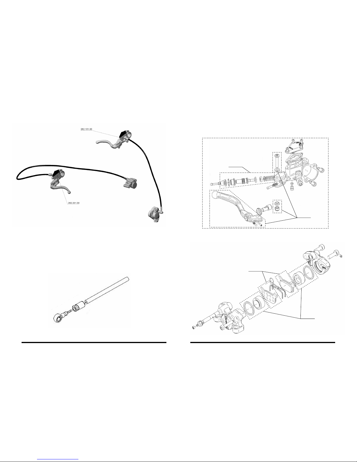
HYDRAULIC BRAKES
HOSE
HYDRAULIC BRAKE LEVER
g. 26 g. 28
g. 29
g. 27
rear brake
front brake
342.225.00
342.222.00
342.226.00
342.230.00
262.103.00 - Rear hydraulic brake hose L=900
262.203.00 - Front hydraulic brake hose L=450
Applies to front and rear brake
HYDRAULIC BRAKE CALIPER
342.222.00 - Brake lever universal
342.225.00 – Brake piston set
342.220.00 - Brake lever left (hydraulic brake)
342.221.00 - Brake lever right (hydraulic brake)
342.227.00 - Set of O-ring seals:
971.044.00 - O-ring 2x1 (2 pc)
971.049.00 - O-ring 4x1 (1 pc)
971.052.01 - O-ring 6x1 (4 pc)
971.054.01 - O-ring 8x1 (1 pc)
27 28
Page 18
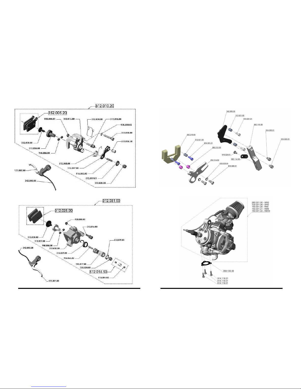
MECHANICAL FRONT BRAKE MECHANICAL BRAKES HOLDER
g. 30 g. 32
g. 33
g. 31
MECHANICAL REAR BRAKE ENGINE - COMPLETE
29 30
Rear mechanical brake
holder - 262.216.00
Front mechanical brake
holder - 262.112.00
Page 19
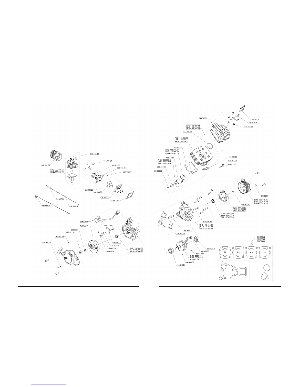
31 32
ENGINE R40, RM9, RM14
g. 34
260.300.00 - Engine R40 set
260.400.00 - Engine RM9
260.500.00 - Engine RM14
Page 20

ENGINE W40
g. 35
260.200.00 - Motor W40
33 34
Page 21
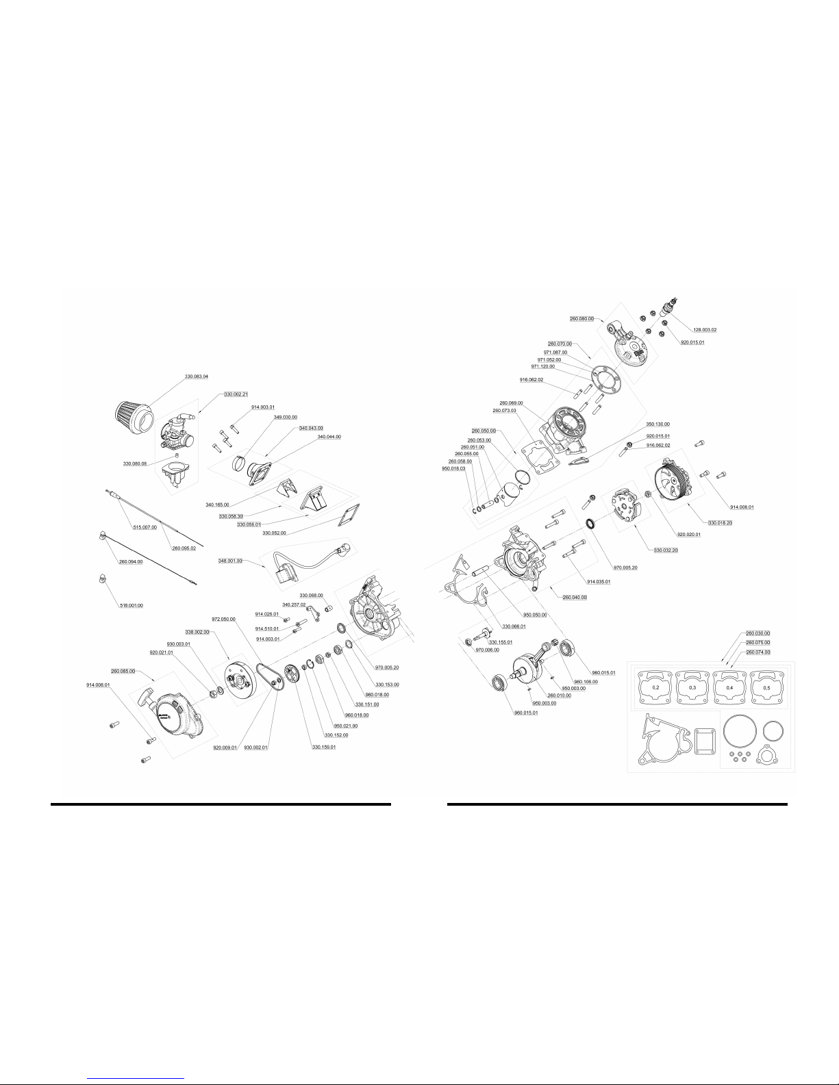
ENGINE W50
g. 36
260.001.00 - Motor W50
35 36
Page 22
330.024.40 - KIT
330.024.00 - SERIE
330.028.20 - KIT
330.028.01 - SERIE
330.085.20 - KIT
330.028.00 - SERIE
330.085.60 - KIT
330.085.50 - SERIE
914.008.01 - KIT
914.001.01 - SERIE
950.008.00
960.009.01
950.009.00
330.029.00
960.012.00
ROTOR CLUTCH CASE COMPLETE
STARTER CASE COMPLETE CLUTCH - COMPLETE
330.015.00
330.021.00
330.022.00
330.017.00
930.020.01
950.025.00
330.141.00 - KIT
330.140.00 - KIT
914.023.01 - KIT
916.007.02
g. 37 g. 39
g. 38 g. 40
37 38
338.002.00
260.085.00
330.018.20 - KIT
330.018.01 - SERIE
330.032.20 - KIT
330.032.00 - SERIE
Page 23
DIAPHRAGM COMPLETE HEAD BLAST - WATER COOLING
g. 41 g. 43
39 40
EXHAUST R40 (RM9, RM14)
g. 42
260.350.00
330.058.01
330.073.42 - W40
260.080.00 - W50
330.071.22 - W40
260.081.00 - W50
310.040.00 330.051.00 330.120.00
obr. 44
150.073.30
HEAD BLAST - AIR COOLING
Page 24
FRONT FORK FRONT WHEEL
REAR WHEEL
263.050.00 - Disk front lightweight
263.053.00 - Disk front standard
335.033.02
335.033.02
263.051.00 - Disk rear lightweight
263.052.00 - Disk rear standard
Chains
517.001.24 - MINI
517.001.46 - MIDI
g. 45 g. 46
g. 47
41 42
Page 25
FRAME
261.570.00 - Seddle support, aluminium pair
261.571.00 - Seddle support, carbon pair
261.572.00 - Rear fork support mini alumium pair
261.573.00 - Rear fork support mini carbon pair
261.574.00 - Rear fork support midi alumium pair
261.575.00 - Rear fork support midi carbon pair
foot rest left complete - 261.610.00
- 261.613.00
- 261.612.00
- 916.006.01 (2x)
- 912.051.01
foot rest right complete - 261.620.00
- 261.613.00
- 261.621.00
- 916.006.01 (2x)
- 912.051.01
TANK - COMPLETE
RADIATOR
269.052.00
319.001.01
g. 48 g. 49
g. 50
43 44
set of hoses + clips - 269.050.00
- 319.012.01 (1x)
- 319.012.02 (1x)
- 319.012.03 (5x)
- 319.012.05 (1x)
- 269.103.00 (1x)
- 269.104.00 (1x)
- 269.105.00 (1x)
- 269.106.00 (1x)
- 269.107.00 (1x)
- 269.116.00 (1x)
- 129.007.00 (2x)
radiator set - 269.100.00
- 269.130.00 (1x)
- 269.110.00 (1x)
- 269.131.00 (1x)
- 269.105.00 (1x)
- 269.106.00 (1x)
- 319.012.03 (2x)
- 269.120.00 (3x)
Page 26
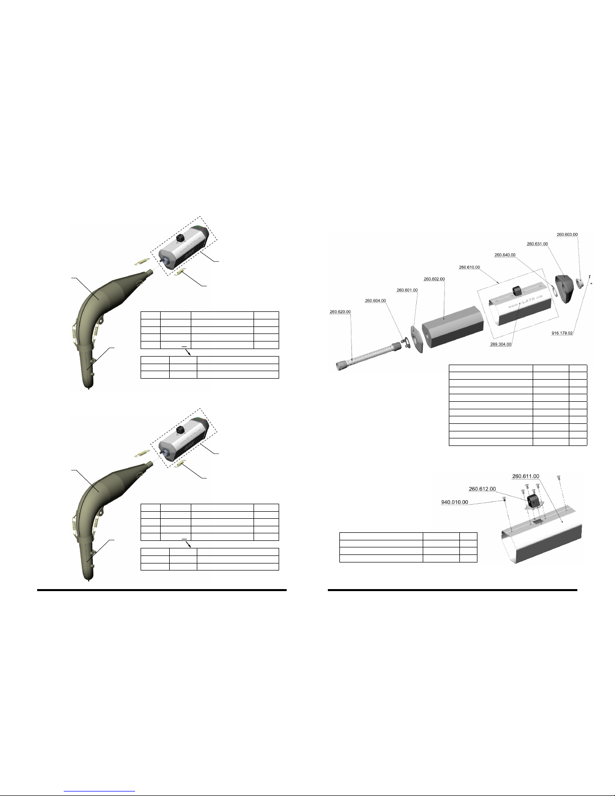
EXHAUST SILENCER STANDARD 260.600.00
SILENCER BODY COMPLETE, STANDARD 260.610.00
EXHAUST - COMPLETE W40
EXHAUST - COMPLETE W50
g. 51
g. 52
g. 53
g. 54
EXHAUST SILENCER
260.701.01 Exhaust W40 set - standard
260.701.02 Exhaust W40 set - carbon cap
260.701.03 Exhaust W40 set - carbon body
260.700.01 Exhaust W50 set - standard
260.700.02 Exhaust W50 set - carbon end piece
260.700.03 Exhaust W50 set - carbon set
ord. no. reg. no. name amount
1 260.151.00 exhaust elbow 2TW50W40 1
2 260.260.00 exhaust middle part 2TW40 1
3 340.105.00 exhaust spring 4
4 260.600.xx exhaust silencer 1
name reg. number pc
perforated tube complete 206.620.00 1
springs plate 260.604.00 1
exhaust cap - front 260.601.00 1
silencer body complete 260.610.00 1
damping substance 260.602.00 1
distance sleeve 260.640.00 1
exhaust cap, standard 260.631.00 1
silencer nut 260.603.00 1
bolt M3 DIN 913 916.179.02 2
sticker www.blata.com size A 269.304.00 2
name reg. number pc
tear-off rivet 4 x 8 940.010.00 6
silencer body standard 260.611.00 1
silencer silent block 260.612.00 1
ord. no. reg. no. name amount
1 260.151.00 exhaust elbow 2TW50W40 1
2 260.160.00 exhaust middle part 2TW50 1
3 340.105.00 exhaust spring 4
4 260.600.xx exhaust silencer 1
260.701.01 260.600.00 exhaust silencer
260.701.02 260.600.10 exhaust silencer carbon cap
260.701.03 260.600.20 exhaust silencer carbon body
260.700.01 260.600.00 exhaust silencer
260.700.02 260.600.10 exhaust silencer carbon cap
260.700.03 260.600.20 exhaust silencer carbon body
2
2
1
1
3
3
4
4
45 46
Page 27
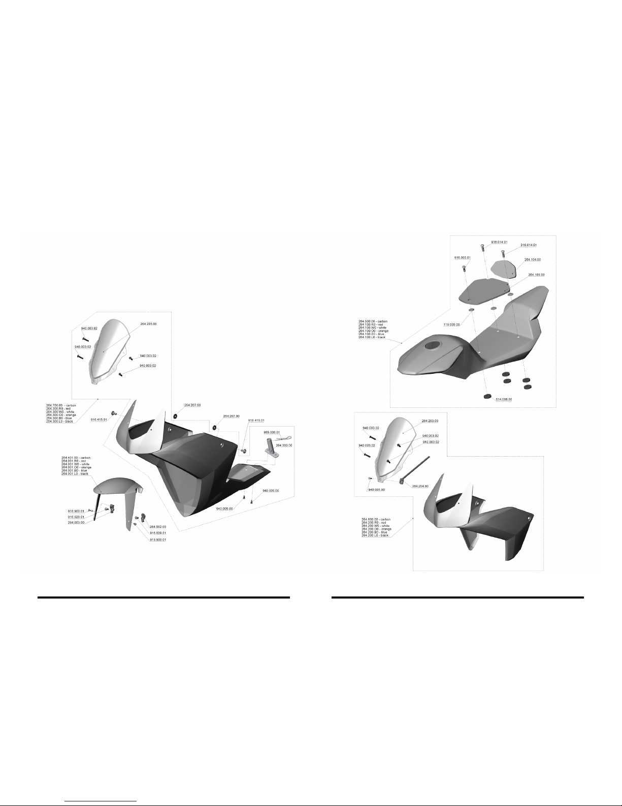
g. 55
COWLING
47 48
Page 28
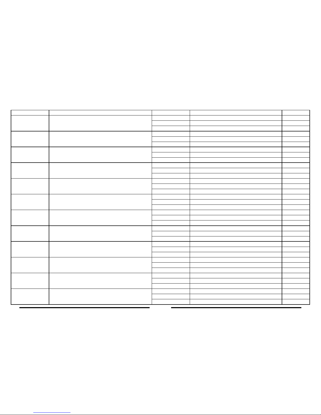
COWLING TABLE
reg. number name reg. number name amount
264.050.0B whole - cowling complete set, blue
264.300.B0 front whole - cowling complete, blue 1
264.100.B0 saddle - cowling complete, blue 1
264.001.B0 front fender glass ber - blue 1
264.050.0L whole - cowling complete set, black
264.300.L0 front whole - cowling complete, black 1
264.100.L0 saddle - cowling complete, black 1
264.001.L0 front fender glass ber, black 1
264.050.0O whole - cowling complete set, orange
264.300.O0 front whole - cowling complete, orange 1
264.100.O0 saddle - cowling complete, orange 1
264.001.O1 front fender glass ber, orange 1
264.050.0R whole - cowling complete set, red
264.300.R0 front whole - cowling complete, red 1
264.100.R0 saddle - cowling complete, red 1
264.001.R0 front fender glass ber, red 1
264.050.0W whole - cowling complete set, white
264.300.W0 front whole - cowling complete, white 1
264.100.W0 saddle - cowling complete, white 1
264.001.W0 front fender glass ber, white 1
264.051.0B semi - cowling complete set, blue
264.200.B0 front semi - cowling, complete, blue 1
264.100.B0 saddle - cowling complete, blue 1
264.001.B0 front fender glass ber, blue 1
264.051.0O semi - cowling complete set, orange
264.200.O0 front semi - cowling, complete, orange 1
264.100.O0 saddle - cowling complete, orange 1
264.001.O0 front fender glass ber, orange 1
264.051.0R semi - cowling complete set, red
264.200.R0 front semi - cowling, complete, red 1
264.100.R0 saddle - cowling complete, red 1
264.001.R0 front fender glass ber, red 1
264.051.0W semi - cowling complete set, white
264.200.W0 front semi - cowling, complete, white 1
264.100.W0 saddle - cowling complete, white 1
264.001.W0 front fender glass ber, white 1
264.060.0C whole - cowling complete set, carbon
264.500.00 saddle - cowling complete, carbon 1
264.700.00 front whole - cowling, complete, carbon 1
264.401.00 front fender carbon 1
264.061.0C semi - cowling complete set, carbon
264.500.00 saddle - cowling complete, carbon 1
264.600.00 front semi - cowling, complete, carbon 1
264.401.00 front fender carbon 1
264.040.01 whole - cowling complete set, unpainted
264.300.*0 front whole - cowling, complete, unpainted 1
264.100.*0 saddle - cowling complete, unpainted 1
264.001.*0 front fender glass ber, unpainted 1
49 50
Page 29

Thank you for the favor which you have shown to our machine BLATA ULTIMA and we
wish you many true racing experiences on the track.
the company BLATA
The company BLATA reserves the right to change the technical design, text and shape of the vehicle.
Serial number: ..................................................... CZ
Signature of the technical inspection: ..........................................................................
This manual serves also as a CERTIFICATE OF WARRANTY. When taking over the
product please make sure that the correct serial number and date of sale are stated in
this certicate of warranty. It is necessary to present this properly lled out certicate
of warranty in the case of a claim.
The providing of the warranty does not affect the rights of the purchaser, which are
bound to the purchase of the item according to special legal regulations.
Date, stamp and signature of the dealer:
IDENTIFICATION INFORMATION
The following identication information will help you
during service solutions and ordering spare parts.
1. Serial number – stamped on the frame head pipe
2. Manufacturing label – glued on the front fork
3. Conguration code - table
1
2
51 52
size motor type of fairing frame color material / color of fairing front fork rear supports wheel disks exhaust mufer
steering s.
absorber
brakes
N / mini A / RM9 W / whole R / red C / natural carbon ber C / carbon C / carbon L / light-weight B / carbon body Y / yes H / hydraulic
D / midi B / RM14 S / semi W / white R / red glass ber S / standard S / standard S / standard C / carbon cap N / no M / mechanic
C / R40 O / orange W / white glass ber F / carbon adjustable S / standard
D / W40 G / gray O / orange glass ber G / standard adjustable
E / W50 B / blue B / blue glass ber
L / black glass ber
Page 30
Pražská 9
678 01 Blansko
Czech Republic
tel.: +420 516 522 111
fax: +420 516 522 100
e-mail: [email protected]
news, list of dealers, current lists of spare parts,
additional equipment offers, reports from races and other
important information can be found at:
The electronic version of this brochure can be found at www.blata.cz.
COPYRIGHT © BLATA 2009
BLATA s.r.o. contact to dealer
www.BLATA.cz
 Loading...