

Page 1
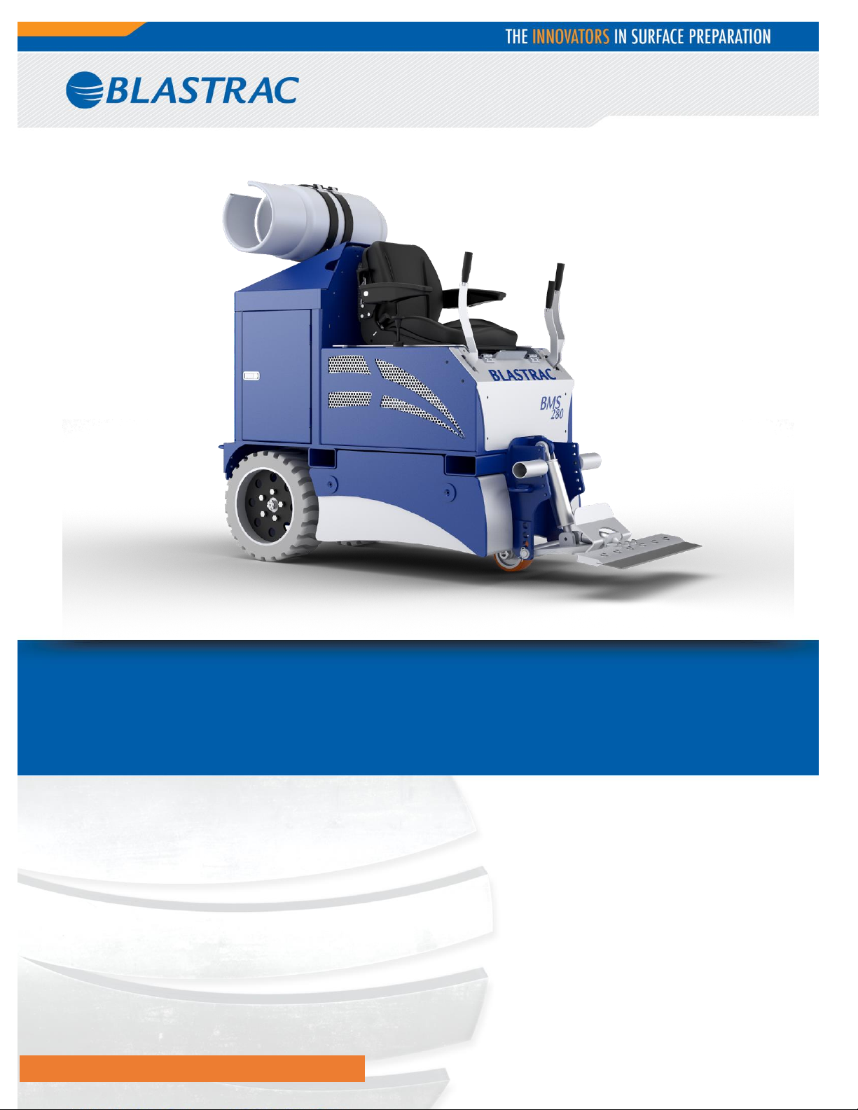
OPERATING MANUAL BMS-280LP
VERSION 1.0
www.blastrac.com 1-800-256-3440
Page 2

Table of Contents
1. Introduction .......................................................................................................................................... 3
2. Machine Description ............................................................................................................................... 3
3. Safety .................................................................................................................................................. 4
Safety Precautions ............................................................................................................................... 4
Safety Regulations ............................................................................................................................... 4
Safety Instructions ............................................................................................................................ 4-7
4. Initial Operation..................................................................................................................................... 8
Checkpoints of Gas Cylinder Safety: ....................................................................................................... 8
Checkpoints of Machine Safety: ............................................................................................................. 8
5. Operation ............................................................................................................................................. 9
Driving the Machine ............................................................................................................................ 10
Controlling Tool Position Cylinder ......................................................................................................... 11
6. Maintenance ................................................................................................................................... 12-13
Hydraulic System Instruction ............................................................................................................... 14
7. Cutting Head & Blades ..................................................................................................................... 15-17
8. Blade Application ............................................................................................................................ 18-22
9. Ditching ......................................................................................................................................... 23-24
10. Technical Data ................................................................................................................................... 25
11. Contact ............................................................................................................................................. 26
2
Page 3
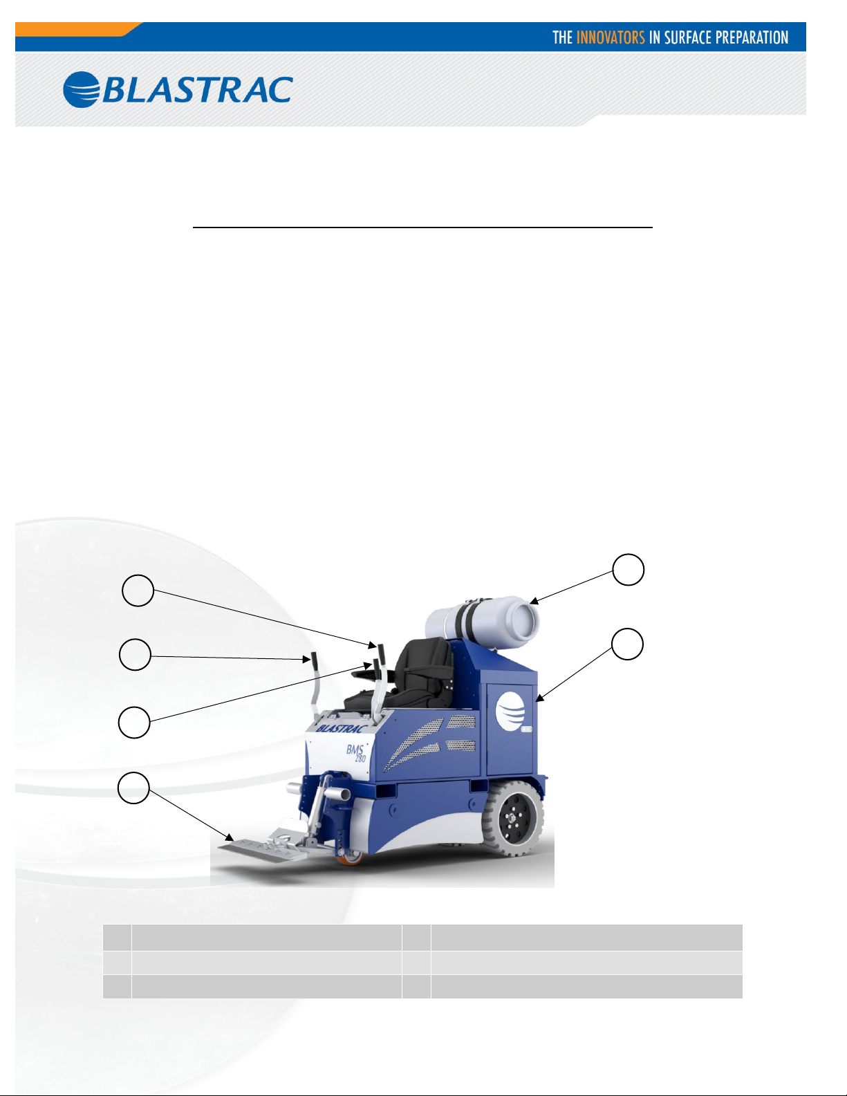
1
Propane Tank (Vapor Propane Type)
4
Left Wheel Drive Lever
2
Engine Housing/Cover
5
Right Wheel Drive Lever
3
Tool Holder
6
Tool Lift/Lower Lever
1 6 5 4 3
2
1. Introduction
It is important that all persons who are working or maintaining this machine read the manual carefully and
understand it fully. Keep this manual near to the machine, so it can always be consulted.
Only authorized and trained personnel may operate this machine.
2. Machine Description
The Blastrac BMS-280 ride-on scraper is ideally suited for medium and large sized applications with the added
benefit of being gas operated for increased versatility. It is very maneuverable with zero turn radius, non-marking
tires and complete hydraulic control.
Main advantages of the BMS-280:
- Fast and easy removal of all types of flooring material
- Very compact, goes through standard doors & elevators
- Zero turn radius, ergonomic design for safe maneuvering, non–marking tires
- Very versatile, total freedom of movement, no electric cable.
- Complete hydraulic control (drive and tool control)
- Powered by a heavy duty motor delivering strong power with no worries of charging.
- Very high output compared to manual material removal.
3
Page 4
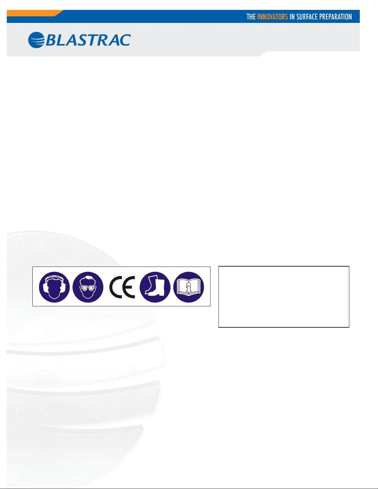
Meanings of these symbols are:
Ear protection is required
Safety glasses with lateral
protection are required
CE-mark on this machine
Safety shoes required
Consult the manual before
operating the machine
3. Safety
It is important that all persons who are working with or maintaining this machine must read the manual carefully
and understand it fully.
Always keep this manual with the machine, so it can be referenced to at any time.
Safety Precautions
Make sure that persons who are not operating the machine are not in the surrounding area of the
machine.
Make sure that there is nothing standing or situated on the surface to be treated
Make sure that there are no cables or hoses in the driving direction of the machine.
Always drive backwards when driving up to a ramp or grade, and forwards when driving down the ramp.
Do not consume drugs or alcohol prior to or during the use of this machine.
Safety Regulations
Never change anything from the safety devices on the machine!
Persons who are not operating the machine must not be permitted to stay within 20 feet of the machine.
Always call a skilled electrician or your distributor when you have questions about the safety of the
electrical components.
Work on electrical equipment or operating materials may only be undertaken by a skilled electrician or by
trained persons under the guidance and supervision of a skilled electrician as well as in accordance with
the electrical engineering regulations.
The following sticker is placed on the machine.
Personnel must tie back long hair and not wear loose clothing or jewellery including rings.
Wear gloves and dust mask during operation of the machine.
Safety Instructions
Turn key to OFF when machine is parked.
o Park the machine always on a flat horizontal and levelled surface.
o Cover the sharp blade or remove it when the machine is off.
Make sure the machine is clean and that the footrests are dry and free of grease and oil.
NEVER lift the machine with the mounted tool for maintenance! This sharp tool can be very dangerous!
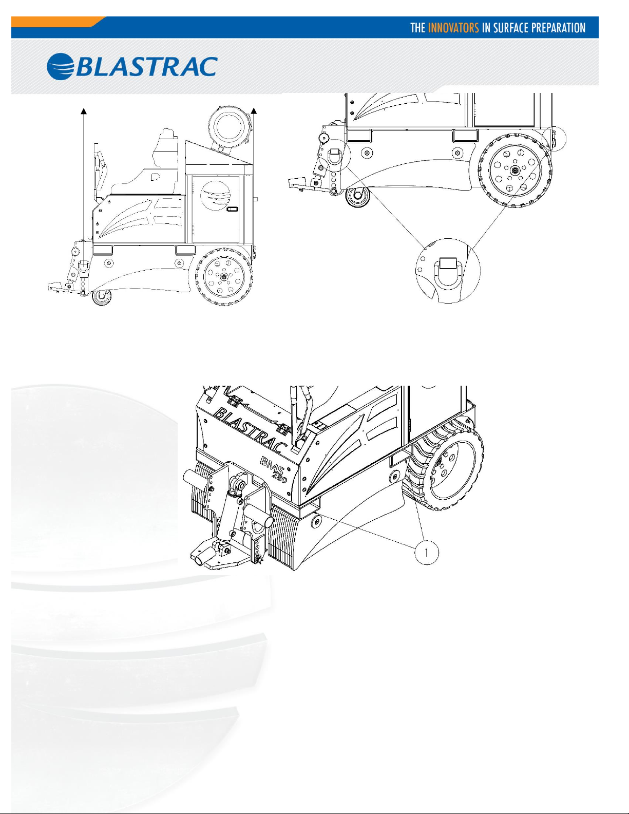
The weight of the BMS-280 is 2900 pounds. Only use an appropriately sized lift or crane to move/hoist the
BMS-280. The lift points are as shown below.
4
Page 5
Chock wheels for transport and keep control handles in neutral position.
Don’t leave the machine unsecured on jobsites.
Machine can be lifted by a forklift. For this use forklift pockets (1) in the middle of the machine:
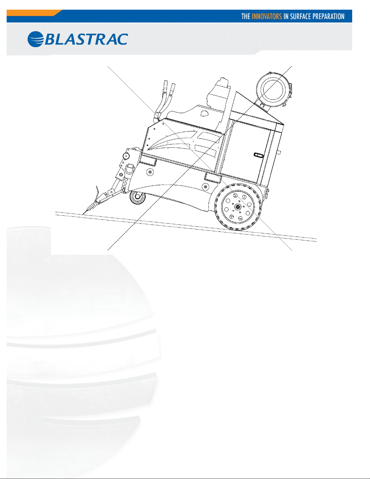
Be aware of your surroundings and machine operating level. Do not run across hill, do not run on steep
incline, this could cause machine to tip over.
Always drive backwards when driving up to a ramp or grade, and forwards when driving down the ramp.
Do not run the machine in unsafe environments.
5
Page 6
6
Page 7
DANGER: Engine exhaust gases contain poisonous carbon monoxide. Carbon monoxide
is odorless and colorless and can cause injury or death if inhaled. Do not use equipment
indoors without adequate ventilation. Refer to OSHA guidelines and regulations
concerning maximum levels of exposure to carbon monoxide gases and other hazards
associated with using internal combustion engines. It is highly recommended that a CO
(carbon monoxide) detector be used to warn the user if levels become unsafe.
Warning: Engine, exhaust system and hydraulic component temperatures could be in
excess of 200F causing severe burns if touched.
Engine Safety
7
Page 8

4. Initial Operation
Befor each use it is essential to inspect the machine.
It is not permitted to use the machine if it does not pass all of the checkpoints below.
Checkpoints of Gas Cylinder Safety:
Check the bottle for any damage before use.
Ensure hose to gas cylinder is fully seated and sealed before turning on the bottle.
Always turn the bottle completely on before starting the engine.
Always turn the bottle completely off after using the machine.
Checkpoints of Machine Safety:
Control levers should be in neutral position.
All hydraulic hose connections are tightened and there is no leakage of oil.
The safety functions and operating functions work correct.
There are not any loose nuts or bolts.
8
Page 9
5. Operation
During the operation of the BMS-280, the following additional safety instructions must be followed closely.
Switching on the Machine:
Turn the valve on the propane tank CCW until it stops.
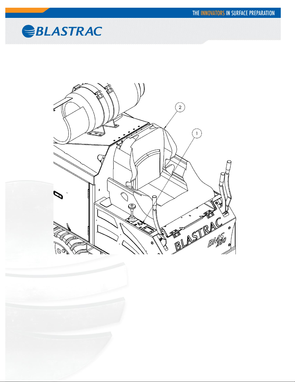
Take place on the seat (2) and put feet on the footrests. Operating the machine without being seated is
not possible because of the safety switch of the seat.
Turn the key contact switch (1) to the right.
9
Page 10
Driving the Machine
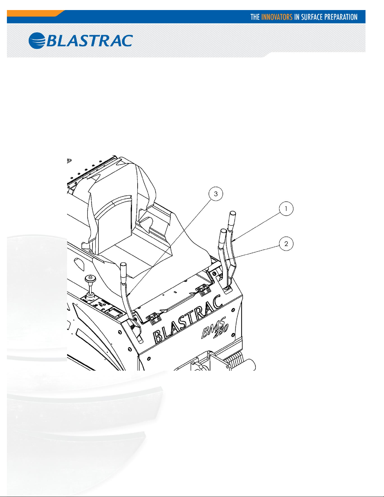
The wheels of the machine are controlled by the two outside handles (1 and 3). Pushing both handles forwards,
the machine drives forwards. Pulling both handles backwards, the machine drives backwards. The driving speed
depends on the position of the handles. Pushing the right handle forwards the machine turn to the left. Pushing
one handle forwards and pulling another handle backwards the machine will turns around its axis. Correcting
direction while moving is accomplished by slightly reducing pressure on one handle or the other while moving.
1) Left wheel control handle.
2) Tool positioning control handle.
3) Right wheel control handle.
10
Page 11
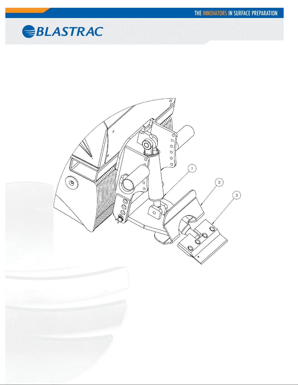
Controlling Tool Position Cylinder
The tool position cylinder is controlled by the left inner handle. Push the handle to lower the tool and pull the
handle to lift the tool to the proper cutting angle. Continuing to push the handle will lift the front of the machine.
This will need to be done when doing maintenance on the machine. When lifting the machine like this, immediately
place blocks under the machine. Never use the cutting head only.
1) Hydraulic cylinder
2) Debris deflector
3) Cutting head - set
11
Page 12
Warning: Engine, exhaust system and hydraulic component temperatures could
be in excess of 200 F causing severe burns if touched.
Operating hours/
time period
Inspection points, maintenance instructions
12 h after repairing
Check all accessible screw connections for tight seat.
Daily and prior to
starting work
Check all safety devices working adequate.
Check the function of the residual current operated device.
Check the hose connections for tightness and fixed seat.
Check the electric connections for sediments of dirt or foreign bodies.
Check the electric motors for dirt and other contaminants.
Annually
Full overhaul and cleaning of the complete machine.
6. Maintenance
Pay attention to Chapter 3 "Safety" during maintenance and repair works.
Failures due to inadequate or incorrect maintenance may generate very high repair costs and long downtimes of
the scraper. Regular maintenance, therefore, is imperative.
Operational safety and service life of the scraper depend, among other things, on proper maintenance.
The following table shows recommendations about time, inspection, and maintenance for the normal use of the
scraper.
The time indications are based on uninterrupted operation. When the indicated number of working hours is not
achieved during the corresponding period, the period can be extended. However a full overhaul must be carried out
at least once a year.
Due to different working conditions it can’t be foreseen how frequently inspections for wear checks, inspection,
maintenance, and repair work ought to be carried out. Prepare a suitable inspection schedule considering your own
working conditions and experience.
Our specialists will be happy to assist you with more advice.
12
Page 13

Follow additional operating and maintenance of OEM if included during
your service and maintenance work.
Store the cleaned and dry machine in a dry and humid free room. Protect the components from moisture, heat,
dust and shocks.
All repair work must to be done by qualified Blastrac personnel, this is to guarantee a safe and reliable machine.
Any guarantee on the machine is expired when:
Non original Blastrac parts have been used
Repair work is not done by qualified Blastrac personnel
Changes or conversions without the express written consent of Blastrac NA
13
Page 14
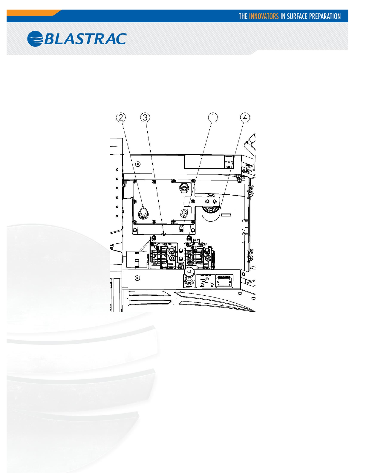
Hydraulic System Instruction
To check the oil level on the side of the tank is an installed indicator. The level shouldn’t be lower than half the
range of the indicator. On top of the reservoit is a plug which can be removed to fill the reservoir.
1) Oil level indicator
2) Plug to refill oil tank
3) Drain Plug
4)Oil Filter
At least one time during the year the oil from system and filter should be replaced. For this operation disconnect
the battery as well as remove the LPG tank. The oil drain plug is located on the side of the machine near the
indicator.
Before doing any maintenance, disconnect the power and block machine in stable position. Because most of
fittings in machine are O-ring style, it is important is to know how to solve O-ring leaks. Fittings should be
tightened with the proper wrench size. Over tightening could damage O-rings. If a leak still persists, remove fitting
and replace O-ring.
14
Page 15

7. Cutting Head & Blades
Weight vs. Sharpness
The most common way to compensate for a dull blade is to add more weight and raise the blade angle (see rescrape setting). Weight allows dull blades to be used to a point. Weight also causes blades to dull and break
easier. Blades of any thickness tend to catch cracks and expansion joints and will bend or break the blade if set at
a high angle. For best results, run a small ditching blade at a low angle to identify as many cracks and joints as
possible. If blades are breaking, you are misunderstanding the conditions.
Cutting Head Angle
Set the cutting head angle to where the material comes up the easiest. The lowest is usually the best.
Steep Cutting Head Angle
A steep angle is only used for re-scraping. The slide plate has to be raised so the bottom of the slide plate is
higher or even with the bottom of the guide channels. Not raising the slide plate when operating the machine at a
steep angle will cause the machine to jump and buck. It does not give the operator a clear vision of the cutting
head and it causes the machine to operate at an unsafe operating height. Failure to raise the slide plate could
cause machine damage and/or bodily injury.
00
Swivel Head
The swivel head keeps the blade in contact with the floor even when the floor is uneven. When using a flat blade
with no bevel, flipping the blade to the other side after it dulls is one of the fastest methods to keep the machine
running as much as possible.
Saving Time With Extra Cutting Heads
The machine is supplied with one cutting head. Having additional cutting heads will save time on the job. Insert
blades into the extra cutting heads before starting a job. When the blade is dull, instead of taking the time to
replace it or sharpen it on the job, take out the cutting head and replace it with another. When a different type or
size of blade is needed, you can already have them ready in additional cutting heads.
15
Page 16
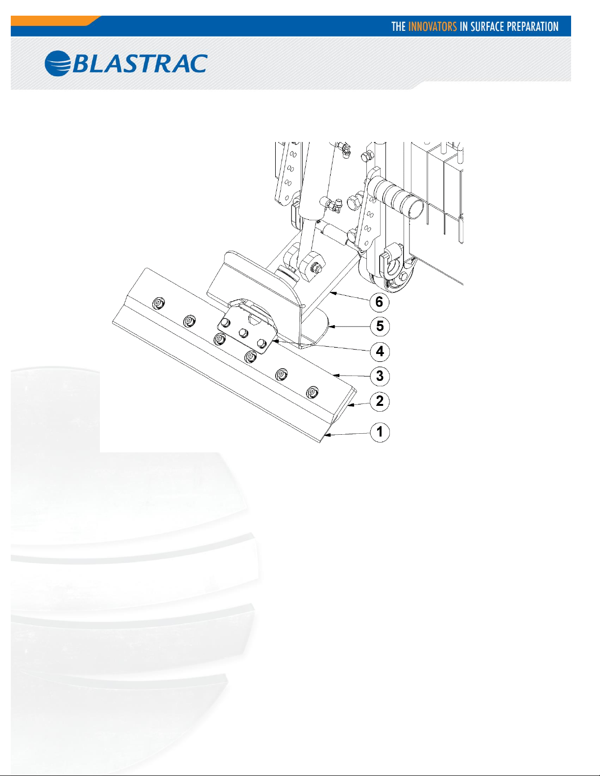
1) Tool – depending of the needs
2) Tool holder – lower part
3) Tool holder – upper part
4) Tool holder
5) Debris deflector – new holder shape
6) Universal lower cutting head support
Cutting Head Insertion
With machine off, insert desired cutting head into cutting head holder. Secure with cutting head clip.
Shank Blade Insertion
Shank blades do not require a cutting head. Insert desired shank blade into cutting head holder. Secure with
cutting head clip.
16
Page 17
Blade Setting
• Dull blades greatly reduce cutting ability. Re-sharpen or replace as needed.
• Proper blade size and placement, depending on material and sub-floor type, affects performance.
• If the material isn’t coming up easily, use a smaller blade for best results.
• Start with a narrow blade, then increase blade size to optimize cutting pass. Narrower blades work
easier than wider blades and usually clean the floor better. Wider is not always better or faster.
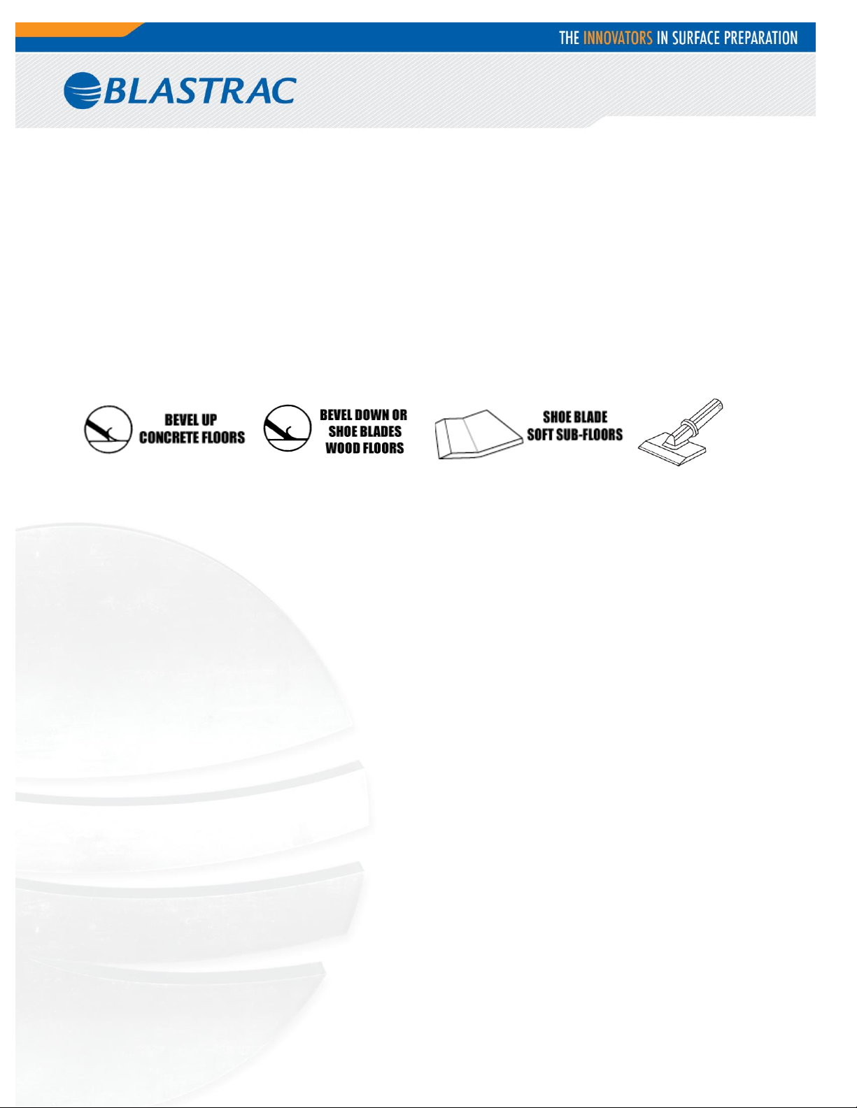
• Normally bevel on blade is up for concrete. Bevel down for wood and shoe blades for soft sub-floors.
• KEEP BLADES SHARP.
• Dull blades greatly affect the performance of the machine and reduce cutting ability, re-sharpen or replace as
needed.
• Keep your work area clean and clear of debris.
• After you have removed a portion of material, remove it out of the way. This will give the machine maximum
performance and help to keep the work area safe.
• Always wear gloves when handling blades.
• Everyone in work area should wear eye protection.
17
Page 18
8. Blade Application
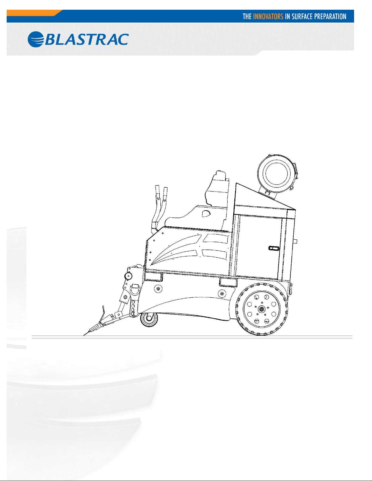
A great deal of work can be accomplished in a short amount of time using the scraper. To do this however, the
operator must use the correct blade type and correct blade angle. Often when the blade begins to dull, it is
tempting to raise the angle of the blade. This method can be used for small amounts of time to ensure the same
quality of cut; however, too high of an angle can result in broken blades. When the angle of the blade to the floor
is too great, the machine can also buck and jump resulting in a tip over, and grave injury to the operator. Never
operate the machine at an angle is that unsafe for the working conditions of the job.
When the blade is dull it is necessary to immediately sharpen or replace. In that operation a second cutting head
can be immediately swapped on to save time. When the machine is running on the second set of tooling the first
set can be serviced to ensure constantly ready tooling.
18
Page 19
Concrete Floor
Wood Floor
Many different floor conditions exist but the hard and fast rule for scraping is that the tougher the material being
removed, the skinnier the blade. The best course of action is to start small and the move to wider blades as per
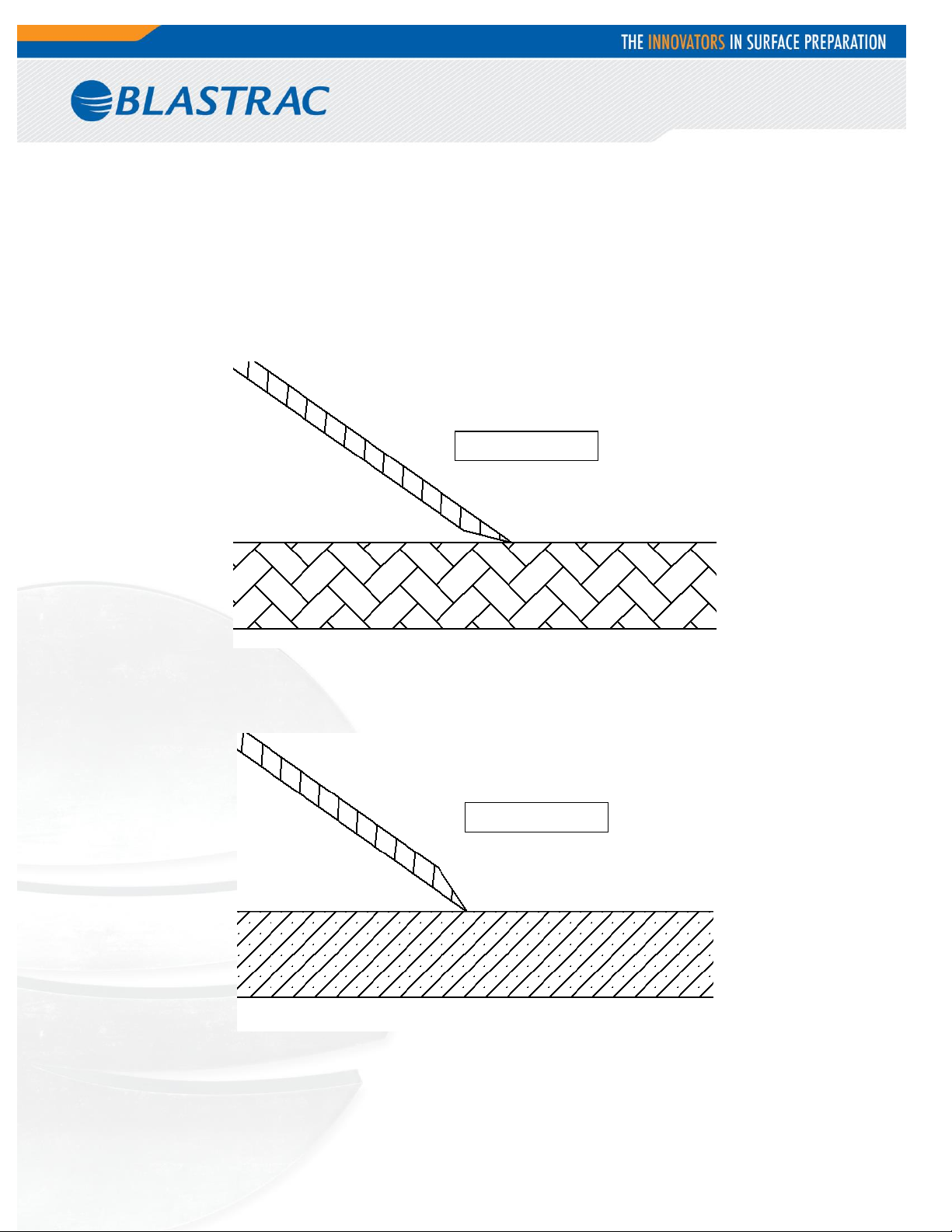
the conditions of the job. Generally speaking, wood floors require the bevel to be faced down, as shown below:
On concrete the bevel must be faced upwards:
Working place should be keep clean. Furthermore; ensure the floor is cleaned before crosshatching to ensure the
best possible material removal. Excess debris and dirt can make the blade dull quickly.
19
Page 20
Wings
Dull blades can be sharpening by using electric grinder with disc of 120 grit or finer. Also a tooth hand file can be
used. Caution is required during sharpening.
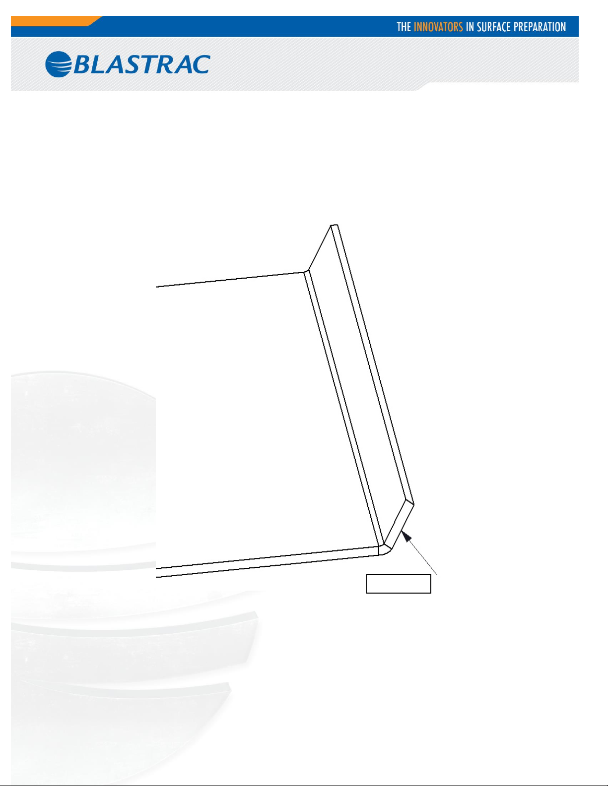
For soft materials like carpet, vinyl, and membranes it is possible to use self-scoring blades:
It’s important to keep the “wings” sharp. They can be sharpened by the same way as the other blades.
20
Page 21

Types of Blades
Different blades are required for different materials and different sub-straights. Although the choice is situation
dependent, below are describe a few examples of common industry practice:
- Self-scoring blades used to vinyl, carpet tiles, soft to medium PVC, soft cork, linoleum,
enhancer and unibond hot melts. Scoring is made automatically by the “wings” of the blades.
- Heavy duty blades are prepared to work on wood, thin ceramic, tile, VCT, VAT, re-scraping
thin set, glued ceramic, elastomeric coating, or rubber epoxy. After some work period the
blades need to be sharpened.
- Shoe blades/angle shank blades for ceramic, thin set, wood, decorative concrete, mud set.
- Extra heavy duty blades for wood, VCT, VAT, thin ceramic, re-scraping, all carpets,
elastomeric coatings, cork, rubber, and urethane coatings.
- Premium tempered blades for VCT, VAT, rubber tile, cork, all glued carpets, and elastomeric
coatings.
- Razor/scraper blades for thin mil coatings (urethane paint), thin epoxies, poured
elastomeric, and hard to remove adhesive.
- Shoe blades/angle shank blades with carbide tips for wood, ceramic, elastomeric
coatings and epoxy.
Using correct blades is only half of being successful. Second is to put the tool in optimal geometry to the ground.
Listed below is a basic guideline to the most popular angles for specific materials:
- VCT tiles: slide plate with distance between 1/4” to 1/2" from floor. It’s better to start with
narrow cutting head.
- Foam back carpet set-up: slide plate with distance from 1/4” to 1/2” to the floor. Is possible
to use cutting head from 10” to 14”. In some situations however wider blades can be used.
- Ceramic set-up: slide plate from 1/4” to 1/2”. Best working blades are Shank Blade or Shank
Blade with a carbide tip.
- Secondary backing carpet set-up: slide plate with distance from 1/4” to 1/2” to the floor.
Proposed settings are cutting head from 10” to 26” with Heavy Duty Blades or a cutting head
(10” to 14”) with Self Scoring Blade.
- Double stick carpet set-up: slide plate with distance from 1/4” to 1/2” from floor. In this
case it good to start with cutting head (10” to 14”) with Self Scoring Blade. It is important to
have very sharp blades.
- Wood set-up: slide plate with distance from 1/4” to 1/2” to the floor. Preferred are Shank
Blades, Shank Blades with carbide tips or a cutting head (6” to 8”) with Shoe Blades, Bent
Shoe Blades or Heavy Duty Blades. Machine needs to have angle 45⁰ to the grain of the wood.
21
Page 22

- Thin coating set-up: slide plate with distance from 6” to 8” to the floor or from 1/4” to 1/2”
off the wood. Correct distance need to be set after tests. Preferred application is cutting head
(8” to 26”) with Razor Blades. But it is possible also to work with cutting head (8” to 14”) with
standard blade.
- Re- scraping set-up: slide plate with distance from 6” to 8”. Cutting head (8” to 26”) with
Scraper Blades can be used. Good to remember that the blade should be one step bigger than
the cutting head.
- Working over concrete: it is imperative to orient the bevel upwards. Starting small and then
moving to wider blades is also the normal course of action.
- Working over soft sub-floor: slide plate with distance from 1/4” to 1/2” from floor. Preferred
are Extra Heavy Duty Blade or regular blade. Blades need to be installed bevel up and the
position needs to be flat as is possible. On a regular blade the operator can try to bend up the
corners if the blade is gouging the sub-straight. This should help to mitigate digging into the
floor.
- Working over wood: First ensure that the floor is strong enough to handle to full weight of
the machine plus the operator. Start with none of the weights on the machine. Distance
between slide plate and floor should be from 1/4” to 1/2”. Preferred are Extra Heavy Duty
Blades, shoe blades or regular, always mounted bevel up. It is also important to always keep
the blades as flat as possible to the floor.
22
Page 23
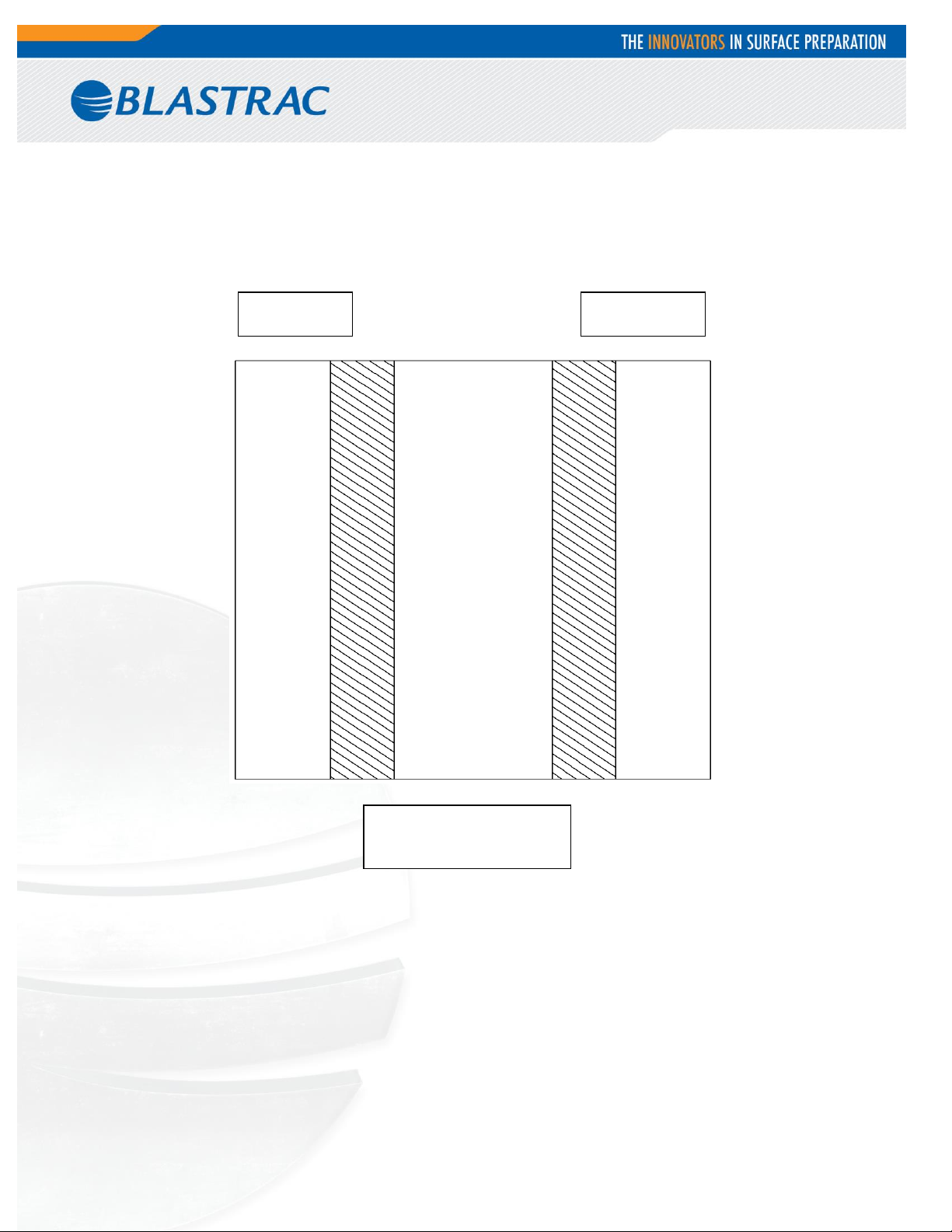
Ditch 2”
To 6”
Tile 12”
To 24”
Run the machine the
same direction that the
ditches are made
9. Ditching
Cross room ditching
When removing hard to remove ceramic, VCT or VAT, cross-room ditching will help to make the removal easier.
Using a blade 2” to 6” in width, make ditches 12” to 24” apart in the same direction the machine will be removing
the material. This “relieves” the pressure holding the tiles together. If ditching helps and the material is coming up
easy, try using a wider blade to ditch with.
23
Page 24
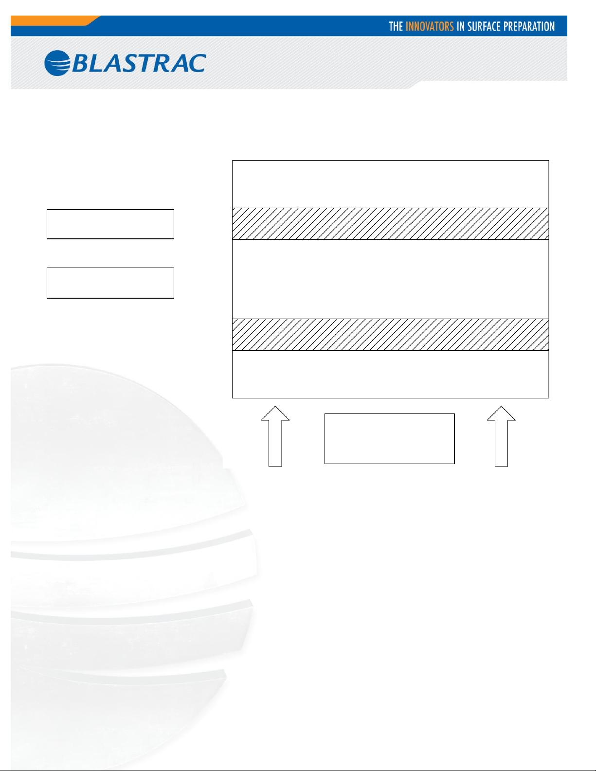
Ditch should be as
wide as possible
Carpet should be from
48” to 72”
Run the machine
crossways from the
directions that the
ditches are made
Checker Board Ditching
To make carpet removal and debris cleanup easier, checker board ditching is very helpful. Using as wide of a selfscoring blade as possible, make ditches apart crossways from the way the machine will be removing the materials.
Running the machine crossways from the ditches will make smaller pieces of debris to be hauled away. Instead of
large gummy rolls of carpet, there are small squares that can be rolled, palletized, put on a dolly or folded with the
sticky side in. This makes removing the debris easier and reduces the amount of debris that can block the
machines movement.
24
Page 25
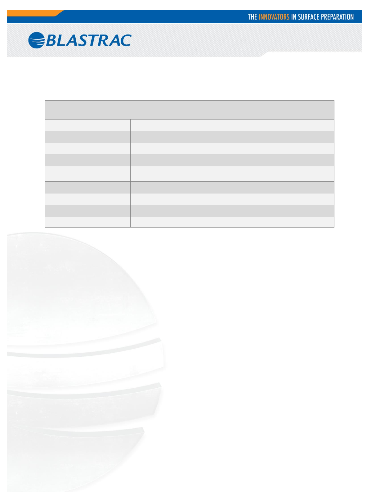
BMS-280LP
Working width
Up to 22”
Motor power
25hp
Drive system/ Speed
Propane- up to 400ft/min
Machine type
Ride-on
Application
Hard Wood Parquet, Ceramics, Linoleum, Vinyl, Carpet, Adhesives,
Glue, Tiles etc…
Length
67”
Width
29”
Height
63”
Weight
2900 lbs.
10. Technical Data
25
Page 26

11. Contact
Blastrac NA
13201 North Santa Fe Avenue
Oklahoma City, OK 73114
Tel: 800-256-3440
Fax: 405-478-8608
www.blastrac.com
26
Page 27
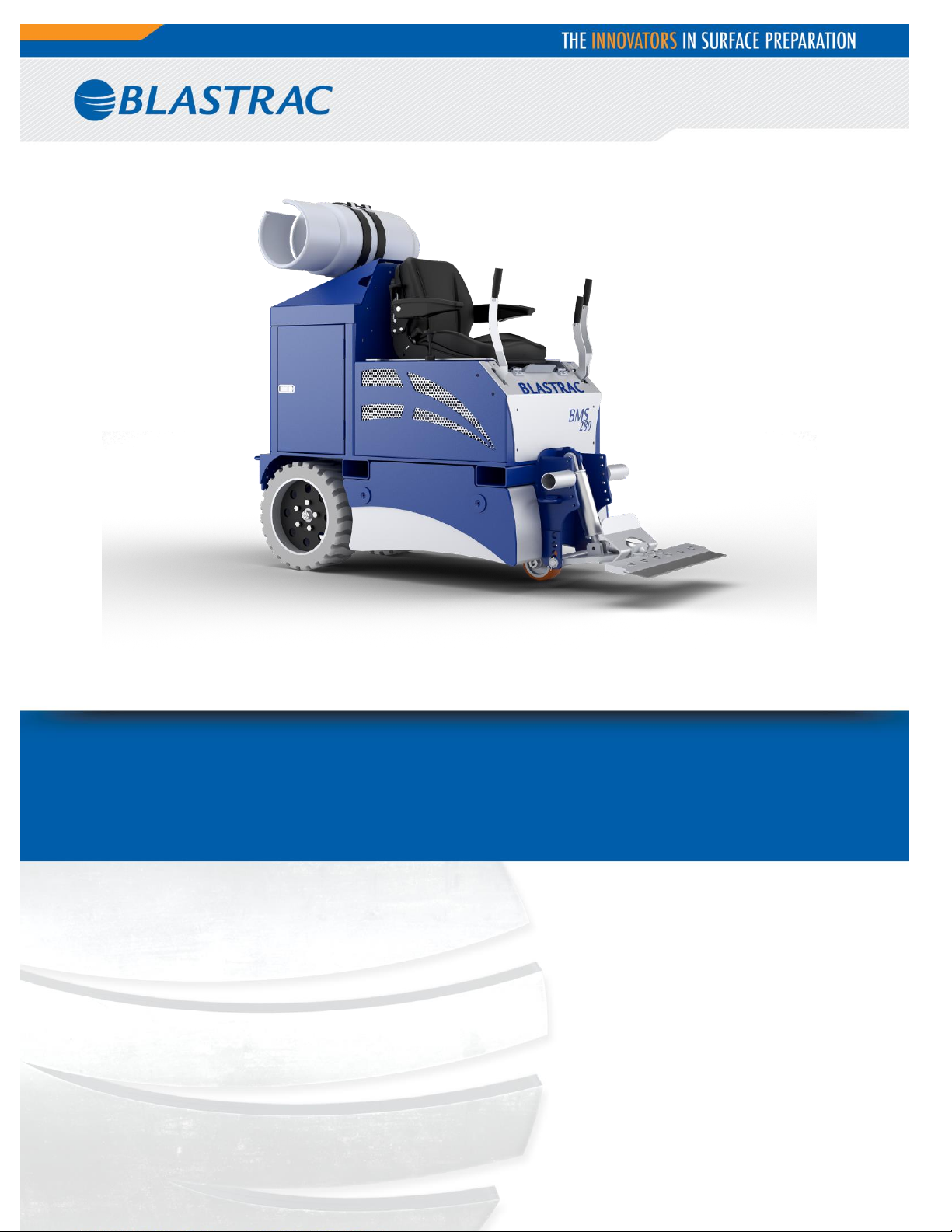
SERVICE MANUAL BMS-280LP
VERSION 1.0
Page 28
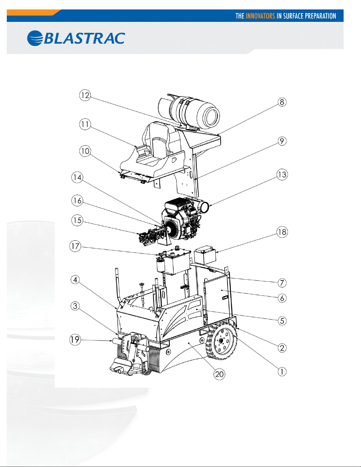
1. Spare parts
Fig. 01
2
Page 29
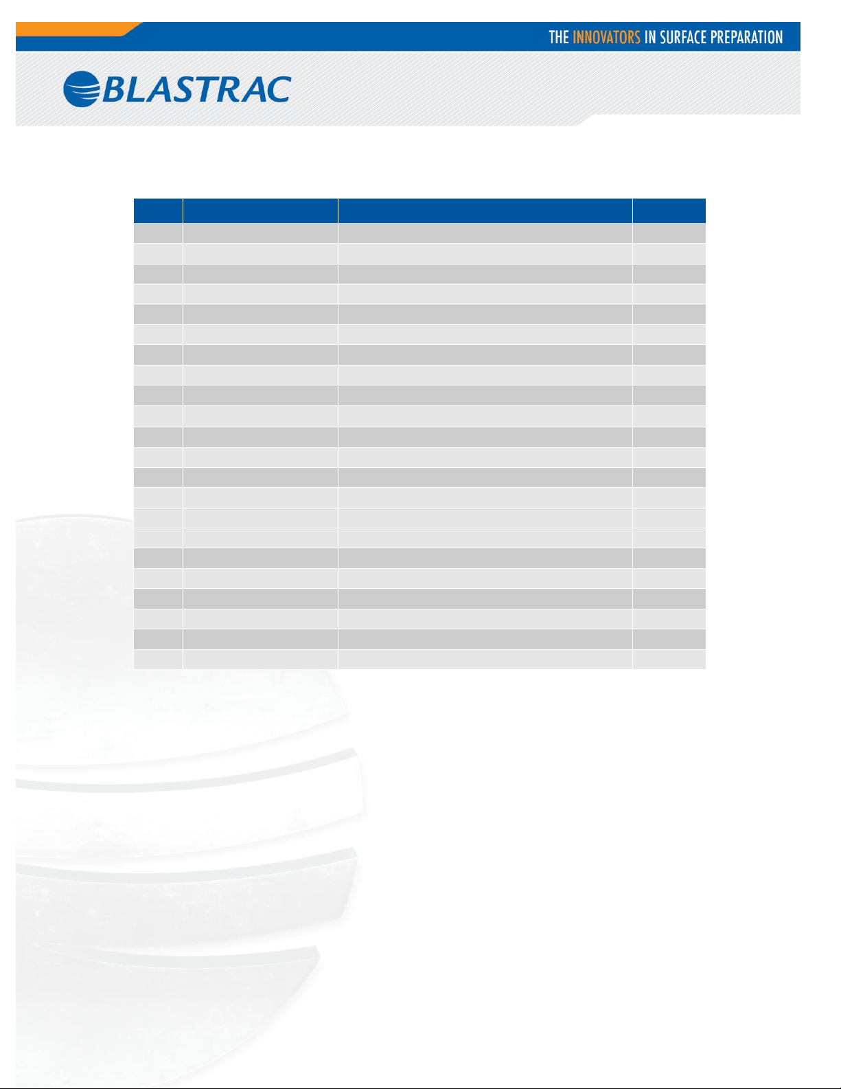
Item
Part number
Description
Qty.
1
PG-10532
Wheel Weldment
2
2
E09716
Tire Scraper
2
3
PG-10530
Frame Weldment
1
4
PA-11214
Front Panel
1
5
PG-10535
Side Panel Left Side
1
6
PG-10547
Door Weldment
2
7
PG-10549
Back Panel
1
8
PG-10545
Hood Weldment
1
9
PG-10548
Middle Panel
1
10
PG-10537
Seat Pan
1
11
CP-10918
Seat / Uni Pro
1
12
07510005
Bracket/Propane
1
13
CP-10735
Engine/Kohler 25hp - BMS-220LP
1
14
CP-10921
Flexible Coupling Hub
1
CP-10922
Jaw Coupling Hub
1
CP-10923
Spider Hytrel Solid Center
1
15
CP-10919
Hydro-Gear Tandem Pumps
1
16
PG-10550
Hydraulic Pump Mount
1
17
CP-10320
Hydraulic Tank 2.6 Gal
1
18
CP-10927
Battery
1
19
E08622
Foot Support
2
20
PG-10533
Weight Cover Left Side
1
Fig. 01
3
Page 30
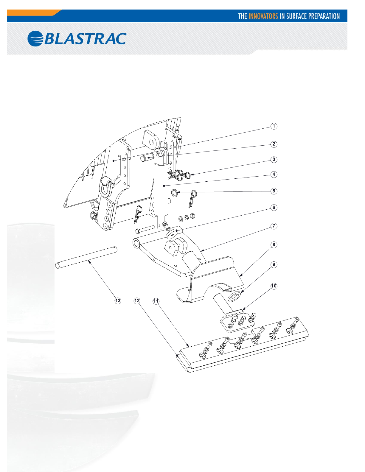
Fig. 02
4
Page 31
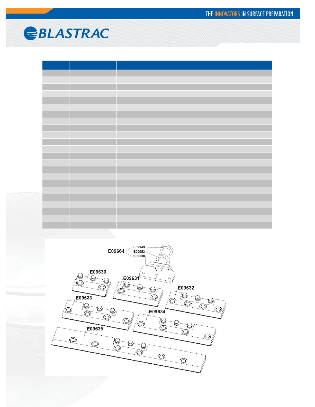
Item
Part number
Description
Qty.
1
PG-10530
Main Frame BMS-280
1 2 E09711
Cylinder Connecting Rod
1 3 BE0234
Locking Clip Double 4,5mm
4
4
E09171
Hydraulic Cylinder
1
5
E11510
Locking Washer
2
6
E09949
Tool Holder Plate
1
7
E12246
Lower Cutting Head
1
8
E09950
Debris Deflector – New Holder Shape
1
9
E09953
Tool Holder Washer
1
10
E09538
Tool Holder
1
6+8+10
E09664
Tool Holder Complete
1
11+12
E09635
Blade Holder 686mm(27”)
1
BE0037
M12x30 Hexagon Bolt
3
BE0027
M12 Spring Lock Washer
3
BE0026
M12 Plain Washer
3
E09630
Blade Holder 152mm(6“)
1
E09631
Blade Holder 203mm(8“)
1
E09632
Blade Holder 254mm(10“)
1
E09633
Blade Holder 305mm(12“)
1
E09634
Blade Holder 355mm(14“)
1
13
E12247
Cutting Head Axle
1
Fig. 02
5
Page 32
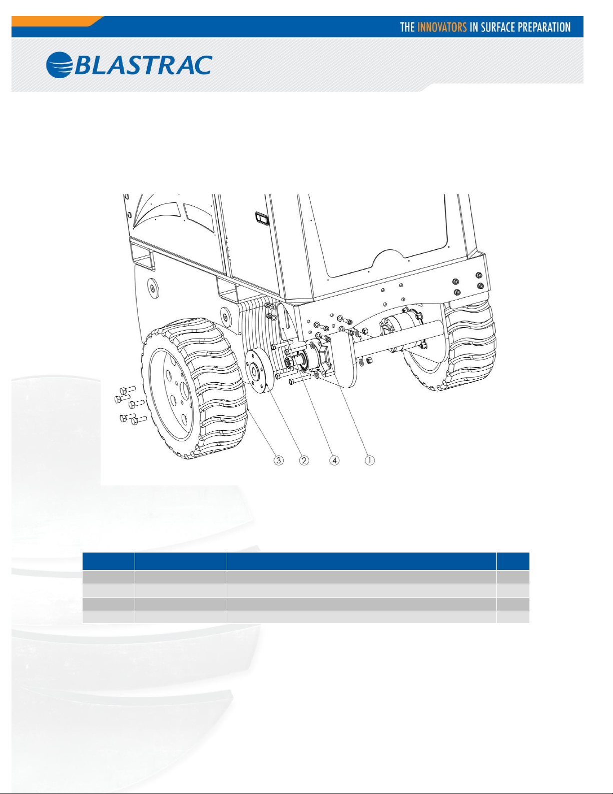
Item
Part number
Description
Qty.
1
CP-10929
Hydraulic Drive Wheel Motor
2
2
CP-10342
Hub/Rear Wheel
2
3
PG-10532
Wheel Weldment
2
4
E09716
Tire Scraper
2
Fig. 03
Fig. 03
6
Page 33
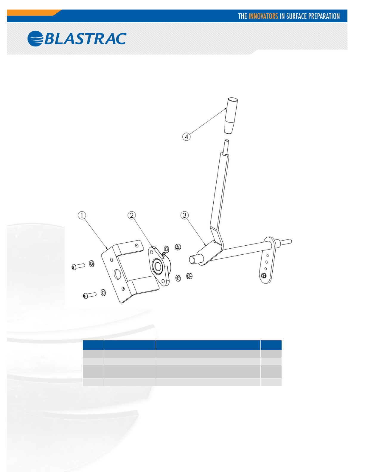
Item
Part number
Description
Qty.
1
PG-10554
Handle Stop Right Side
1
2
CP-10938
Control Bearing/Ball Bearing
1
3
PG-10552
Controls/Handles Weldment
Right Side
1
4
E09701
Handle Grip
1
Fig. 04
Fig. 04
7
Page 34
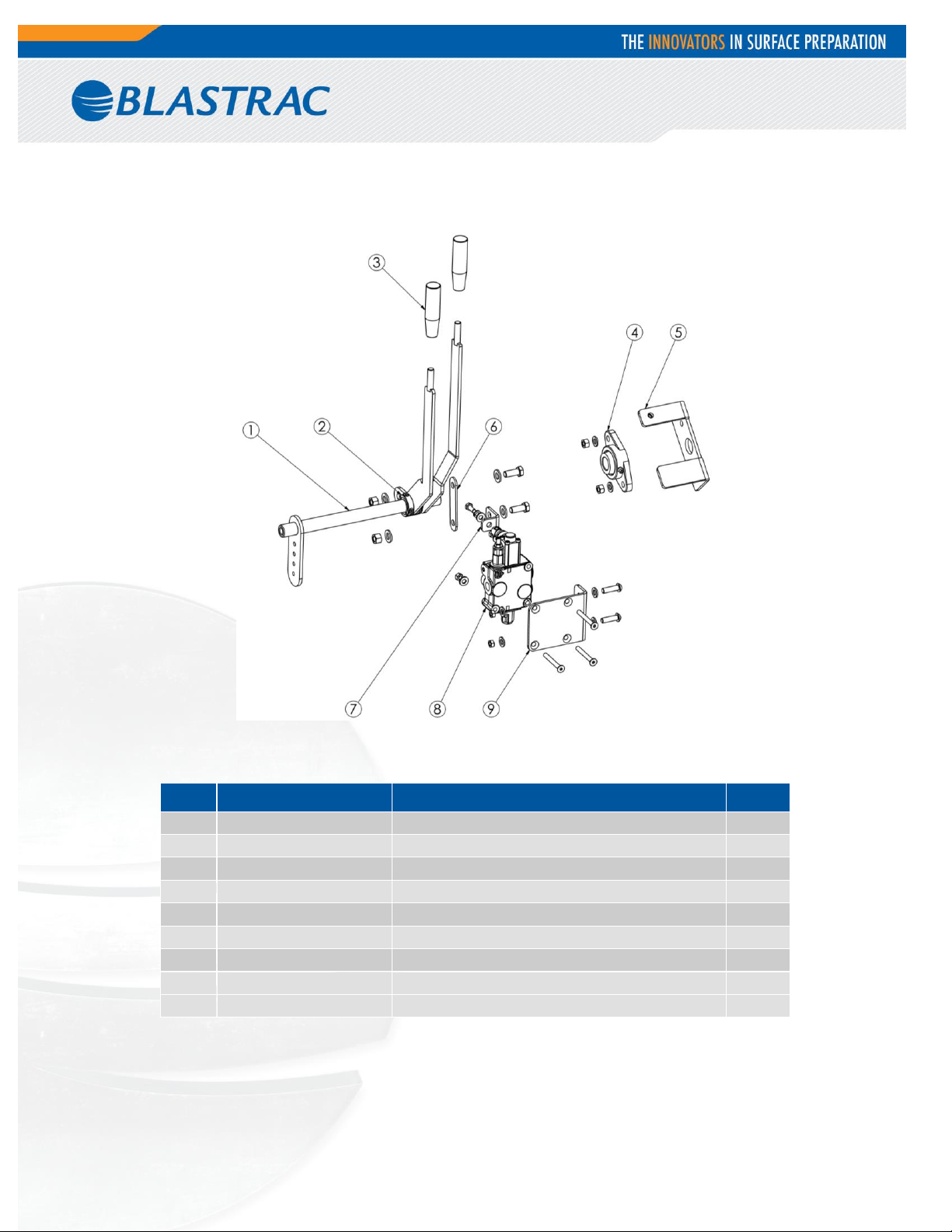
Item
Part number
Description
Qty.
1
PG-10538
Controls/Handles Weldment Left Side
1
2
CP-10939
Shaft Collar
2
3
E09701
Handle Grip
2
4
CP-10938
Control Bearing/Ball Bearing
1
5
PG-10546
Handle Stop Left Side
1
6
PA-11219
Linkage/Link To Handle
1
7
PA-11218
Linkage/Valve To Link
1
8
CP-10920
Spool Directional Control Valve
1
9
PG-10551
Hydraulic Valve Mount
1
Fig. 05
Fig. 05
8
Page 35
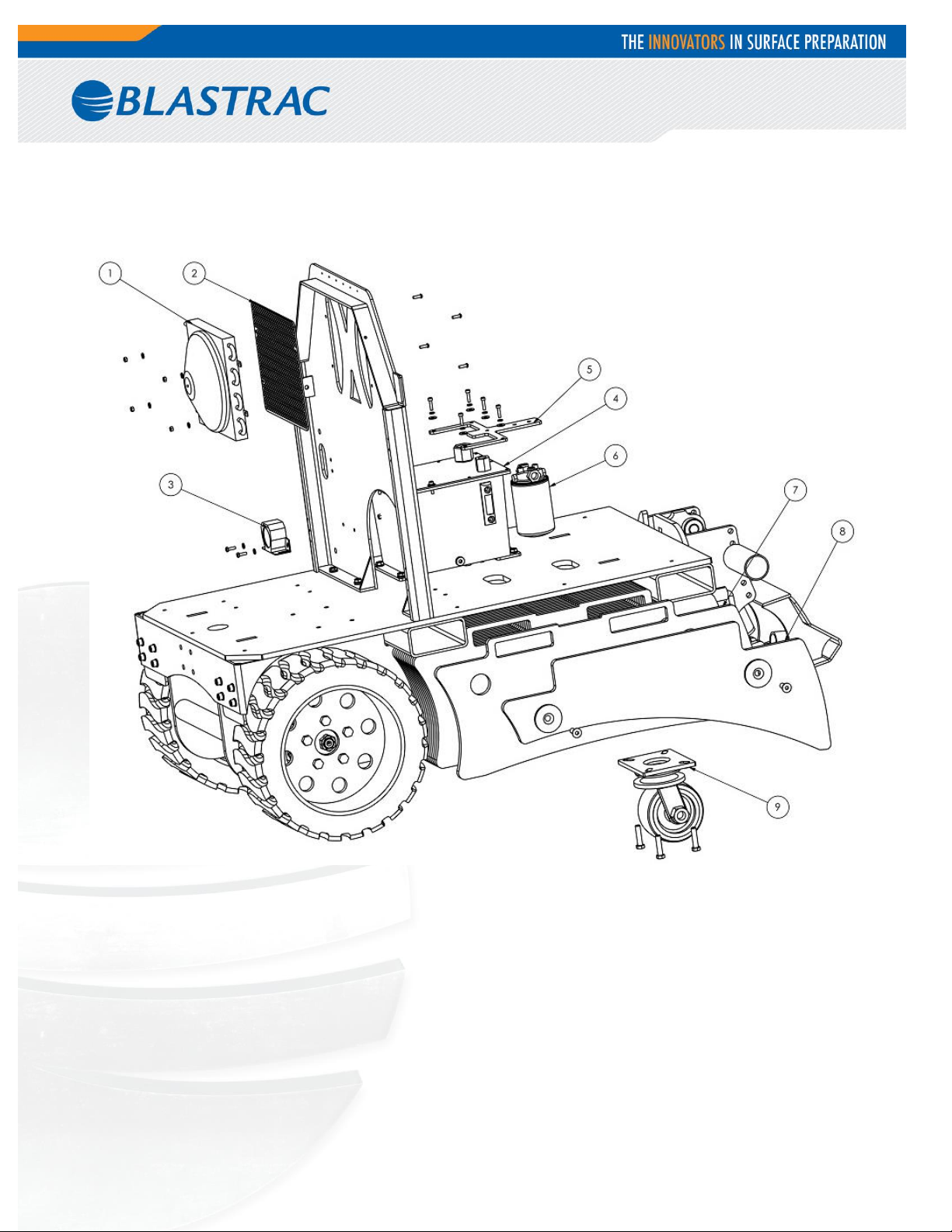
Fig. 06
9
Page 36
Item
Part number
Description
Qty.
1
CP-10746
Dyno-Cooled Remote Fluid Cooler
1
2
PA-11183
Screen/Hydraulic Cooler
1
3
CP-10940
Back Up Beeper
1
4
CP-10320
Hydraulic Tank 2.6 Gal
1
5
PA-11217
Hydraulic Filter Mount
1
6
04210012
Filter/Hydraulic
1
7
PA-11216
Removeable Weights
26
8
PG-10534
Weight Cover Right Side
1
9
P000257
Caster / Swivel
1
Fig. 06
10
Page 37
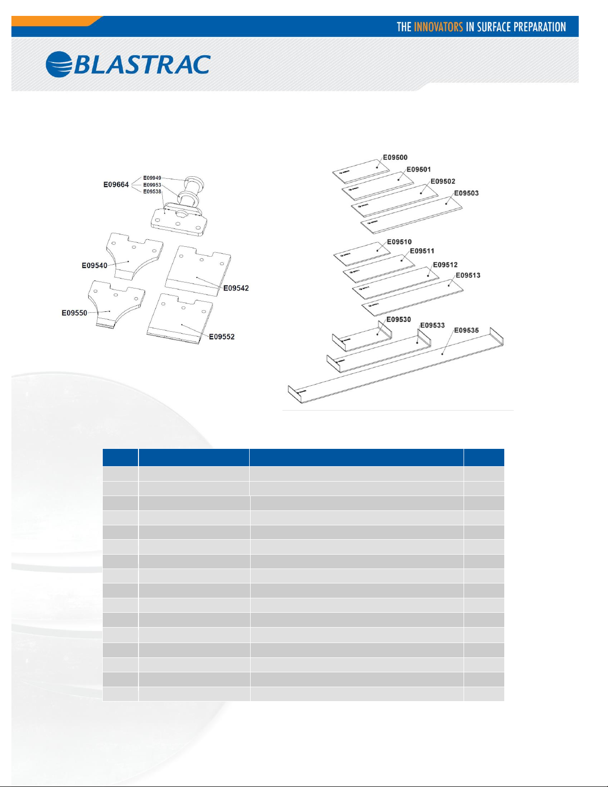
Item
Part number
Description
Qty.
E09664
Tool Holder Complete
1
E09540
Premium Chisel 51x12 (2”)
1
E09542
Premium Chisel 152x12 (6”)
1
E09550
Heavy Duty Chisel 51x12 (2”)
1
E09552
Heavy Duty Chisel 152x12 (6”)
1
E09500
Heavy Duty Blade 152x76x2.5 (6“)
1
E09501
Heavy Duty Blade 203x76x2.5 (8“)
1
E09502
Heavy Duty Blade 254x76x2.5 (10“)
1
E09503
Heavy Duty Blade 305x76x2.5 (12“)
1
E09510
Premium Blade 152x76x1.6 (6“)
1
E09511
Premium Blade 203x76x1.6 (8“)
1
E09512
Premium Blade 254x76x1.6 (10“)
1
E09513
Premium Blade 305x76x1.6 (12“)
1
E09530
Self-Scoring Blade 152x76x1.5 (6“)
1
E09533
Self-Scoring Blade 305x76x1.5 (12“)
1
E09535
Self-Scoring Blade 686x76x1.5 (27“)
1
Fig. 07
Fig. 07
11
Page 38
Date
Findings
Repairs / Cleaning
Test
on
By
(competent person)
Maintenance log
12
Page 39

Warranty Registration Notification
IMPORTANT!
TO THE DELIVERING DISTRIBUTOR OR END USER
To ensure the proper warranty coverage is extended to the owner of this machine, fill
in the necessary information below COMPLETELY and ACCURATELY and retain for
your records. Go to www.blastrac.com and register online. Click on the Register icon
in the left column of the homepage, and fill out the product registration form with the
same information that will be recorded here.
The warranty period will start upon the delivery date of the machine.
The distributor or the end user must provide the machine warranty information when
the machine is delivered. Registration of the machine will extend the warranty period
from the recorded delivery date entered with product registration. Failure to comply
will make any and all warranties on the equipment void after 6 months.
OWNER/END USER’S REFERENCE INFORMATION
Delivery Date _________________________
Delivering Distributor’s Name and Address
_____________________________________
_____________________________________
_____________________________________
Machine Model No._____________________
Machine Serial No. _____________________
Modifications__________________________
_____________________________________
_____________________________________
_____________________________________
_____________________________________
Signature of Delivering Distributor’s Representative
Blastrac is a registered trademark of Blastrac,NA
Fold and Detach Here if Mailing
Warranty Registration
IMPORTANT! To ensure that your Blastrac
the information recorded here by registering online at blastrac.com, or complete this page and fax
to 866-485-1046, or if you prefer, detach and mail to:
Blastrac, 13201 North Santa Fe Avenue, Oklahoma City, OK 73114-9901
(Please print legibly)
_____________________________________
_____________________________________
®
machine is covered under warranty, please provide
Company _____________________________________________________________________
Address ______________________________________________________________________
City, State, & Zip _______________________________________________________________
Telephone No._____________________ Contact Person ______________________________
Date of Purchase___________________ Date Received ______________________________
Machine Model No. __________________________ Serial No. _________________________
Distributor Name _______________________________________________________________
End User Name _______________________________________________________________
End User E-mail _______________________________________________________________
 Loading...