

Page 1

MODEL
BMP-G/E250-X
February 2006
Page 2

Operating Instructions BMP-(G/E)250-X
Section 1 - Safety Precautions February 2006
Section 1
1.1 Warnings and Symbols
1.2 Statutory Safety Considerations
1.3 Primary Safety Considerations
1.4 Safety – Selecting Personnel and Their Qualifications
1.5 Safety – Consideration Under Normal Operating Conditions
1.6 Electrical Safety
1.7 Maintenance Mode
© Blastrac February 2006
1
Page 3
Operating Instructions BMP-(G/E)250-X
Section 1 - Safety Precautions February 2006
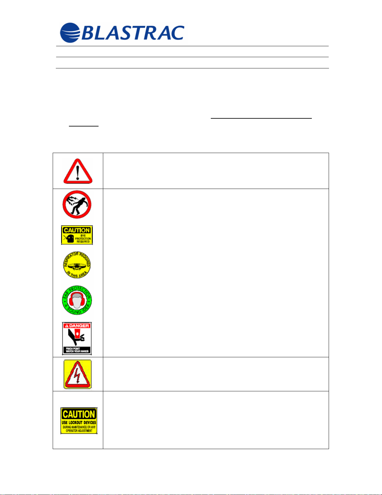
1.1 Warnings and Symbols
This Instruction Manual uses the following symbols to draw your attention to certain
information. Please note that these symbols
machine.
Symbols Used:
Warning of a potential danger to life and limb. Always comply with the
instructions and act with extra care in these cases. Along with these
instructions, you should be familiar with and comply with statutory
OSHA, local government, and site safety and accident
prevention regulations.
may or may not be used on the
Information, directions, and cautions to help prevent injury to persons or
damage to property.
Warning of dangerous voltages or potentially dangerous voltages
Suggestions regarding Lock Out/Tag Out (LO/TO) conditions for this
equipment are also referred to as the “Maintenance Mode”. Many
industrial and commercial facilities have developed their own conditions
and rules for LO/TO with which the operator may be required to comply.
It is the responsibility of the owner/operator of this equipment to develop
a LO/TO procedure that will provide the intended element of safety. One
LO/TO system will not work in all situations. Management must give
© Blastrac February 2006
2
Page 4
Operating Instructions BMP-(G/E)250-X
Section 1 - Safety Precautions February 2006
consideration to personnel training levels.
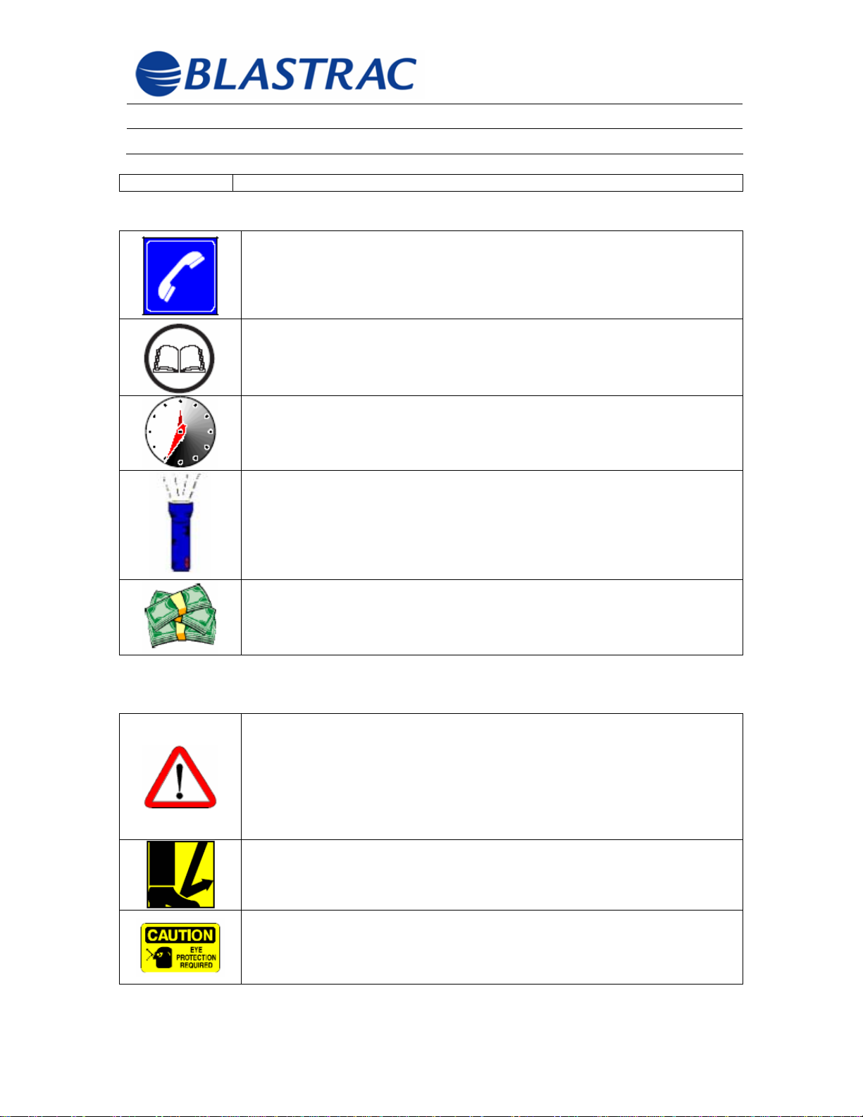
1.1 Warnings and Symbols (cont’d)
Information requiring advice or input from Blastrac.
Details of important information in this Instruction Manual.
Indication of necessary regular or scheduled checks pertaining to
safety, maintenance, and/or operation efficiency.
Troubleshooting tips and suggestions
Special information concerning the economic use of the machine
1.2 Statutory Safety Considerations
In addition to these Manual instructions and cautions, all
statutory and other binding (law) accident prevention regulations
such as OSHA, state and/or local entity articles should be a part
of operator training. This type of obligation may govern, i.e.
handling of hazardous materials or wearing personal safety
equipment. Some of these are listed in the remainder of this
Section 1.2 “Statutory Safety Considerations”.
Safety shoes are required. Observe all applicable local, state and
federal safety regulations. Wear OSHA-approved foot protection.
Eye protection is required. Observe all applicable local, state and
federal safety regulations. Wear OSHA-approved safety glasses
with side shields.
© Blastrac February 2006
3
Page 5
Operating Instructions BMP-(G/E)250-X
Section 1 - Safety Precautions February 2006
1.2 Statutory Safety Considerations (cont’d)
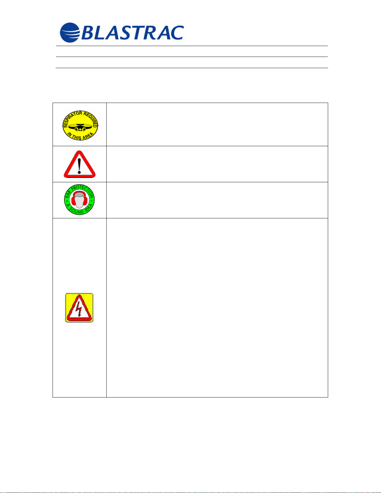
Wear respirator while operating equipment. Avoid air contaminants
including concrete dust. Grinding and cutting concrete produces
airborne crystalline silica. Exposure to airborne crystalline silica can
lead to severe repertory distress, silicosis and even death. Observe all
applicable local, state and federal safety regulations. Wear OSHA
approved respirator when operating this equipment.
Obtain Material Safety Data Sheets (MSDS) for all work surface
materials. This includes primers, all coatings, adhesives, tile materials,
etc. Do not attempt to remove material without MSDS information.
Consult MSDS for hazards information. Keep these MSDS with the
machine.
Wear ear protection when operating equipment. Noise levels of
operating equipment may exceed 85 db (A). Observe all applicable local,
state, and federal safety regulations. Wear OSHA-approved hearing
protection.
Dangerous voltages power this equipment. Operation can be safe if
rules and good practices are observed.
1. It should be standard practice that if damage to an electrical element of the
machine occurs i.e. control panel, cable, etc the repair must be immediate
and factory replacement parts must be used.
2. Particular attention must be given to laws pertaining to equipment
grounding. The following is an excerpt from OSHA 29CFR 1926.404(b)(1)(iii)
and should be considered a minimum guideline for inspection/repair policy for
the owner/operator.
This same verbiage is also present in the National Electric Code.
The employer shall establish and implement an ensured equipment
grounding conductor program on construction sites covering all cord
sets, receptacles which are not a part of the building or structure, and
equipment connected by cord and plug which are available for use or
used by employees. This program
shall comply with the following minimum requirements:
(A) A written description of the program, including the specific
procedures adopted by the employer, shall be available at the jobsite for
inspection and copying by the Assistant Secretary and any affected
employee.
(B) The employer shall designate one or more competent persons . . . . .
The balance of this article may be found at www.osha.gov
© Blastrac February 2006
4
Page 6
Operating Instructions BMP-(G/E)250-X
Section 1 - Safety Precautions February 2006
1.3 Primary Safety Considerations
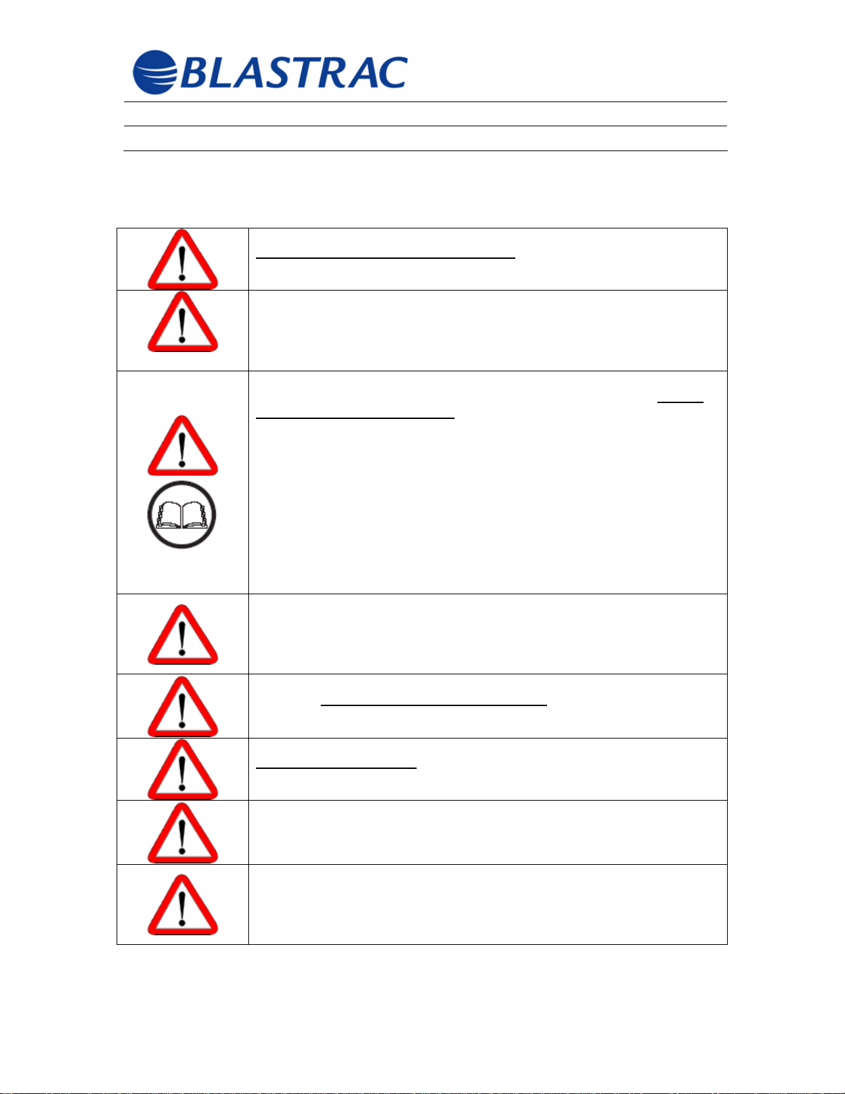
USE COMMON SENSE and BE AWARE!
NEVER leave the machine while it is running. Do not remove hands
from the handle until the machine has come to a complete stop. Turn
power off and place the machine into the “Maintenance Mode”. See
Section 1.5 “Safety – Under Normal Operating Conditions”.
Before starting any work with or on the machine, all authorized
personnel must read and understand the Instruction Manual.
work has started is TOO LATE. This applies in particular to those
persons who only work on the machine occasionally, i.e. setting-up,
maintenance, changing filters, etc.
The Instruction Manual must be supplemented by management
developed rules, including supervisory and personnel levels with
notifying duties, taking special operational features into account, i.e.
regarding work organization, operational sequences, personnel used,
training, etc. Always keep the Instruction Manual in good condition
and with the machine.
Only personnel trained in this manner should operate this equipment.
Alterations, extensions and conversions of the Blastrac® equipment
requires the approval of Blastrac! This applies in particular to the
installation and settings of safety devices,
cabling and to welding work on any supporting parts. Use ONLY
Blastrac® replacement parts!
If changes affecting safety occur to the machine or its operational
behavior,
the fault and correct it immediately!
DO NOT attempt to operate the machine until it has been repaired.
shut the machine off immediately. Determine the cause of
AFTER
Under no circumstances should anyone ever operate these machines
while under the influence of drugs, alcohol, or any medication.
Personnel must not have unprotected long hair, loose clothing or
jewelry, including rings. There is a risk of injury i.e. through hair,
fingers, arms or clothing getting stuck or being pulled into the
machine.
Emphasis should be provided and checks conducted at regular
intervals to ensure personnel are safety conscious and aware of all
the risks and cautions in this Instruction Manual as well as operational
information.
© Blastrac February 2006
5
Page 7
Operating Instructions BMP-(G/E)250-X
Section 1 - Safety Precautions February 2006
1.3 Primary Safety Considerations (cont’d)
The periodic checks and inspections listed in this Manual should be
performed
Blastrac® equipment will continue to operate efficiently, economically
and safely. Failure to perform these checks and inspections will
potentially foster inefficient and unsafe equipment.
Never use the machine unless all safety devices and equipment
affecting safety, e.g. guards, detachable safety equipment, emergency
switches and dust collector is in place and
1.4 Selecting Personnel and Their Qualifications
Stipulate to the machine operators their responsibility and authorize
them to refuse instructions from third parties that contravene safety
regulations! Personnel in training or under instruction may only
operate the machine under the supervision of an experienced person!
Both supervisory and operating personnel should be familiar with the
location and proper use of fire suppression and extinguishing
equipment on site.
Before starting any work with or on the machine, all authorized
personnel must read and understand the Instruction Manual. AFTER
work has started is TOO LATE. This applies in particular to those
persons who only work on the machine occasionally, i.e. setting-up,
maintenance, changing filters, etc.
The Instruction Manual must be supplemented by management
developed rules, including supervisory and personnel levels with
notifying duties, taking special operational features into account, i.e.
regarding work organization, operational sequences, personnel used,
training, etc. Always keep the Instruction Manual in good condition
and with the machine. Only properly trained personnel should be
allowed to operate this equipment.
thoroughly and on time. This will help ensure that the
working!
© Blastrac February 2006
6
Page 8
Operating Instructions BMP-(G/E)250-X
Section 1 - Safety Precautions February 2006
1.5 Safety – Considerations Under Normal Operation
Work on electrical parts of the machine must be preformed by a
qualified electrician or
by experienced persons under the supervision of a qualified
electrician.
ALWAYS INFORM OPERATING PERSONNEL before starting any
special work or maintenance work! When work is carried out that
affects the machine's operations or settings and/or the settings of the
safety devices, complete compliance with this instruction manual is
necessary! This is an important part of the Lock Out/Tag Out
procedure mentioned below.
LOCK OUT/TAG OUT or “Maintenance Mode” of a machine.
The machine must be in a “safe” mode when troubleshooting,
adjusting or maintaining the equipment. The machine state is "safe” to
work on when it is unable to endanger anyone, i.e. no stored energy
that might be released is present. Examples would include:
Electrically the Main switch is disconnected, locked out and tagged
out.
Mechanically the machine and all parts of it are secure i.e. lids
cannot fall, wheels cannot roll, etc.
Any other “stored energy”, such as a spring under tension has been
neutralized.
Before switching the machine ON, ensure no one can be endangered
when the machine starts up!
Check to ensure that the machine power switch is in the off position
before attempting to plug the machine into the main power source!
Make sure that the power plug and receptacle are compatible and that
they fit securely together. If they do not securely fit together, do not
operate the machine!
The machine MUST be connected to an approved dust collector such
as a Blastrac® 4-54DC99, 6-54DC99 or 8-54DC99 when in operation.
NEVER turn off or disconnect the dust collector when the machine is
running!
Always empty the dust container of the dust collector properly.
Comply with waste disposal regulations. If you are unsure of current
regulations contact your local authority. Always dispose of materials
and supplies safely to protect the environment.
© Blastrac February 2006
7
Page 9
Operating Instructions BMP-(G/E)250-X
Section 1 - Safety Precautions February 2006
1.5 Safety – Considerations Under Normal Operation (cont’d)
AVOID DANGEROUS SITUATIONS
• Survey the work area before starting the machine for hidden
obstructions and uneven cracks or joints.
• Do not expose the machine to rain.
How to Execute an Emergency Stop:
9 Operate the Emergency Stop Pushbutton located on the control panel of
the scarifier or, for those machines equipped with a gasoline motor,
activate the dead-man safety switch by pulling the rope. This will remove
all power from the machine.
9 Operate the mechanical quick lift actuator on the scarifier. This will remove
the scarifier drum from the work surface.
9 Switch the dust collector to the off position.
9 Wait until all drives come to a complete stop!
9 Disconnect the main power plugs or lock out the main disconnect switches
of both machines to ensure that no power is being fed to the scarifier or
the dust collector.
• Do not use the machine in standing water conditions.
• Keep work area well lit.
• Do not allow the machine to cross over the edge of the
concrete slab or work surface.
• When working on uneven surfaces, pay attention not to cross
over embedded floor anchors, ledges, or heaved slab joints as
this may lead to machine damage, personal injury, or both.
Check the system thoroughly after each transport and at least once a
day for external damage and defects. As defects or problems are
found qualified personnel MUST correct them immediately.
In the event of an emergency, the operator should execute an
Emergency Stop! A Lock Out/Tag Out or “Maintenance Mode” is
necessary in the event of an emergency!
© Blastrac February 2006
8
Page 10
Operating Instructions BMP-(G/E)250-X
Section 1 - Safety Precautions February 2006
1.6 Electrical Safety
When extending the main cable, use only extension cables that
are dimensioned in accordance with the machine's total output
and with current regulations.
DO NOT ABUSE THE POWER CORD! Never pull the machine by
the cord! Never allow the cord to be run over by a forklift truck
or any other vehicle! Connect the power cord to the power
source and power cable extensions with approved plugs only
and with the machine power switch turned off.
To protect against unnecessary damage, ensure that no
vehicles, such as forklift trucks, can drive over the electrical
cable or the dust hose!
Electrical components must be checked on an ongoing basis.
Electrical cables, enclosures, and safety devices should be
inspected prior to every shift, EVERY day. Always inspect after
transport. A thorough check of the internal terminations should
be accomplished every 3 months.
If defects are found or suspected, contact a qualified electrician
or your Blastrac representative. Defects such as loose
connections or scorched cables must be corrected immediately.
Ensure reliability of voltmeters used for troubleshooting.
© Blastrac February 2006
9
Page 11

Operating Instructions BMP-(G/E)250-X
Section 1 - Safety Precautions February 2006
1.7 Maintenance Mode
Prior to inspecting BMP-G/E250-X components and attached components, verify
that the machine is placed in Maintenance Mode as described below.
Maintenance Mode
Maintenance mode is defined as the state or condition of the BMP-G/E250-X,
which minimizes mechanical and electrical hazards.
The BMP-G/E250-X should be put into Maintenance Mode prior to making
adjustments or attempting any maintenance. The steps for placing the BMP-
G/E250-X in maintenance mode are listed below.
1. Move the BMP-G/E250-X to level ground.
2. For E350-X: Press Off Button located in control panel.
For G250-X: Turn switch on front of motor to Off.
3. Verify all moving parts have stopped.
4. Secure the BMP-G/E250-X against movement due to gravity.
5. For E250-X: Utilize Lock-Out/Tag-Out procedures to verify machine will
not be inadvertently energized during maintenance.
© Blastrac February 2006
10
Page 12

Operating Instructions BMP-(G/E)250-X
Section 2 – Technical Data February 2006
Section 2
2.1 Machine Specifications
2.2 Motor Specifications
2.3 Applications and Proper Use
2.4 Power Requirements for Electric Machine
©Blastrac February 2006
11
Page 13
Operating Instructions BMP-(G/E)250-X
Section 2 – Technical Data February 2006
2.1 Machine Specifications
Manufacturer: Blastrac®, 13201 North Santa Fe, Oklahoma City, OK 73114
Equipment / Code Word: Blastrac Scarifier
Machine Contents upon Delivery: Scarifier (BMP G/E250-X)
Manual (1x)
Dust Collector (option)
Dust Container (option)
Machine Type: BMP = Model
E/G = Motor type
250-X = Working width in millimeters
Machine Dimensions
Length 38.5”
Width 17.5”
Height 44”
Weight 235 lbs.
Weight (with cutters) 255 lbs.
Working Width: 10”
Drive: Manual
2.2 Motor Specifications
BMP-G250-X Gasoline Power: 9hp
BMP-E250-X Electric Power: 5hp, 230V, 3Ø, 60 HZ, 12.4 A
2.3 Applications and Proper Use
All proper applications of these machines have been listed in Section 3.1 “Description
of Machine“.
This machine has been designed for the scarifying of horizontal
concrete, asphalt, and steel surfaces ONLY. All other applications are
deemed to be of incorrect use! Blastrac shall not be liable for any
damage resulting from incorrect use. The user is solely responsible for
any risk.
©Blastrac February 2006
12
Page 14
Operating Instructions BMP-(G/E)250-X
Section 2 – Technical Data February 2006
2.4
Applications and Proper Use (cont’d)
A dust collector system MUST be used with this scarifier. The
minimum requirement of the dust collector is 200 CFM with primary
filter efficiency of 99.9% @ 0.5 Microns
2.5 Power Requirements for Electric Machine
If the machine is to be operated with a generator, the generator must
be connected in accordance with the National Electric Code (NEC).
Particular attention must be given to the equipment grounding
conductor in the system. See Section 1.2, Page 4 “Dangerous voltages
power this equipment. Etc” for explicit information. Only by doing this
are you ensured that all safety devices will function properly and
exclude the possibility of injury of personnel or of damage to electrical
components.
Maximum branch circuit protection for the BMP-E250-X is 15 amp @
230 volt.
Minimum extension cord conductor size is 12 AWG up to 100 feet and
10 AWG to 200 feet.
©Blastrac February 2006
13
Page 15

Operating Instructions BMP-(G/E)250-X
Section 3 - General Information February 2006
Section 3
3.1 Description of Machine
3.2 Electrical Control Operating Elements
3.3 Mechanical Operating Elements
3.4 Scarifier Drum Details
3.5 Scarifier Cutter Details
©Blastrac February 2006
14
Page 16

Operating Instructions BMP-(G/E)250-X
Section 3 - General Information February 2006
3.1 Description of Machine
Blastrac BMP-G/E250-X scarifiers are available with either a 230 V electric motor
or a combustion engine.
BMP-G/E250-X scarifiers with a working width of 10 inches are sturdy and
powerful machines that can be used only on horizontal surfaces.
The depth setting adjustment handle of the machine assures that the subsurface
is protected. Fitted with the appropriate scarifier cutters, the BMP-G/E250-X
scarifiers can be used for various applications, for example:
• Scarifying concrete
• Cleaning only on horizontal surfaces
• Removing coatings and adhesives
• Scoring concrete surfaces
• De-rusting metal surfaces, e.g. ship decks and tanks
• Grinding-away
• De-scaling
• Preparing surfaces for new coatings
The depth setting adjustment handle enables the efficiency of the appropriate
scarifier cutters to be maximized according to the material being removed.
©Blastrac February 2006
15
Page 17
Operating Instructions BMP-(G/E)250-X
Section 3 - General Information February 2006
2
4
1
3
Fig. 3.1
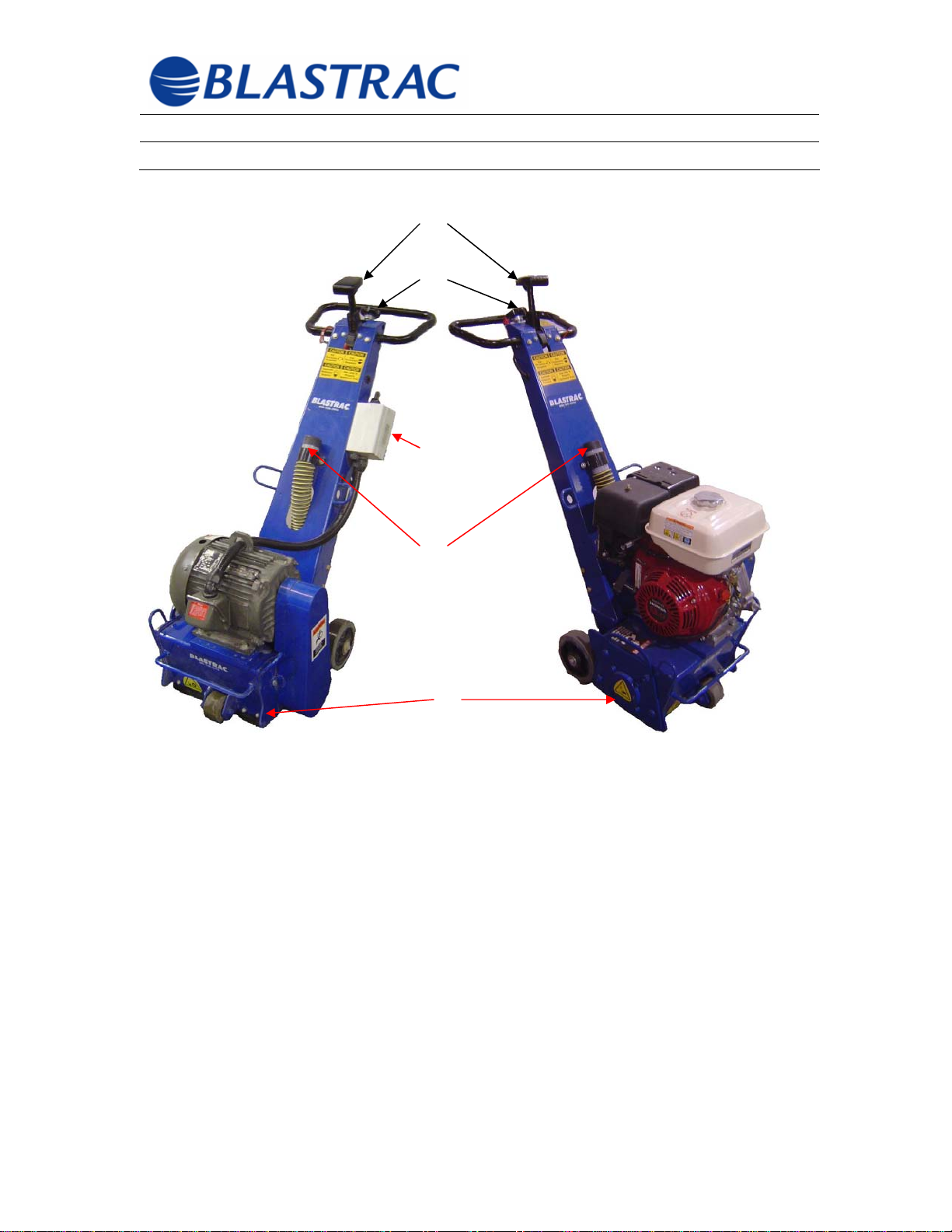
1) Control panel (E250-X only)
2) Quick Lift Actuator
3) Dust Collector Connection
4) Depth Setting Adjustment Wheel
5) Machine Housing
5
©Blastrac February 2006
16
Page 18
Operating Instructions BMP-(G/E)250-X
Section 3 - General Information February 2006
3.2 Electric Control Operating Elements
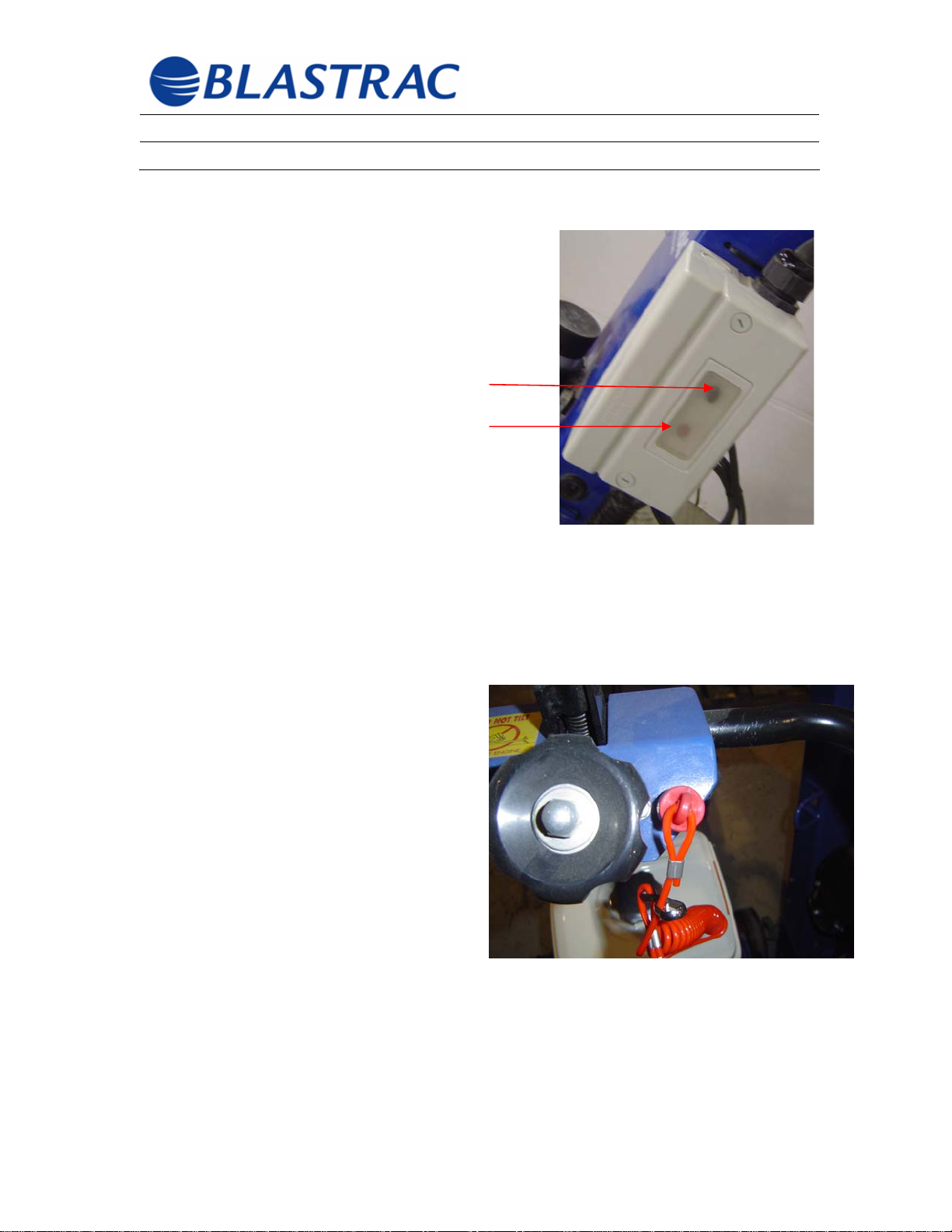
The electrical switchbox shown in Figure 3.2 for
the BMP-E250-X has and Green On button and
a Red Off button.
1) On Button
2) Off Button
1
2
On Button: This button is provided to turn the
machine on. Before switching the machine on,
use the quick lift actuator to lift the scarifier drum
off of the work surface in order to prevent the
motor from starting or coasting under a full load.
Off Button: This button is provided to turn the machine off. Prior to turning the
machine off use the quick lift actuator to lift the scarifier drum off of the work
surface in order to prevent excessive wear to cutters when no actual work is
being accomplished.
In addition to the On and Off buttons,
there is a deadman kill switch with a
lanyard located near the handle. This
should be secured to the operator
during operations. This switch will stop
all machine functions if the operator
should come out of contact with the
machine. See Figure 3.3.
Fig 3.2
Fig 3.3
©Blastrac February 2006
17
Page 19

Operating Instructions BMP-(G/E)250-X
Section 3 - General Information February 2006
3.3 Mechanical Operating Elements
Quick Lift Actuator:
The BMP-G/E250-X scarifiers have a quick lift actuator for the scarifier drum
(See Figure 3.1, Item 2).
The quick lift actuator can be used to lift the scarifier drum without altering the
scarifier depth setting, to transport or move the scarifier or in an emergency
situation.
Depth Setting Adjustment:
Turn the depth setting adjustment wheel or hand wheel to set the scarifier depth
so that the individual scarifier cutters bit correctly (scratch) and the desired
surface profile is obtained. The depth setting adjustment enables the scarier
cutters to be set as deep as required on the surface to be treated.
The scarifier depth should only be set “deep” enough so that the scarifier cutters
are thrown up without obstruction through centrifugal force and can turn freely on
their individual shaft. If the depth setting has been set correctly, the scarifier will
run smoothly and evenly.
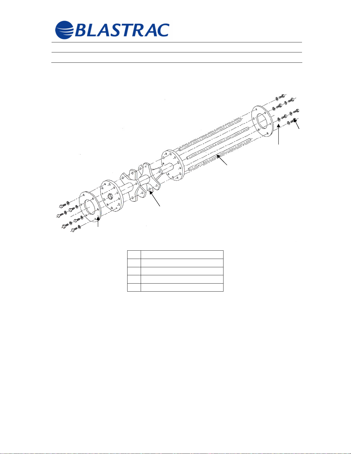
3.4 Scarifier Drum Details
The scarifier drum is the heart of the scarifier. The scarifier drum has a very
simple structure. The individual scarifier cutters are slid onto their individual shaft
with spacer washers as shown in the enclosed assembly plan. The washers
ensure that there is sufficient clearance between the scarifier cutters.
The enclosed component-mounting diagram takes into account a required lateral
play of approximately 1-3mm for the scarifier cutters.
©Blastrac February 2006
18
Page 20
Operating Instructions BMP-(G/E)250-X
Section 3 - General Information February 2006
3.4 Scarifier Drum Details (cont’d)
5
2
4
1
3
1 Drum
2 Shaft
3 Shaft Retainer
4 Screw
5 Lockwasher
©Blastrac February 2006
19
Page 21

Operating Instructions BMP-(G/E)250-X
Section 4 - Transport February 2006
Section 4
4.1 Transporting the Machine
4.2 Moving the Machine by Hand
4.3 Transporting with Lifting Gear
4.4 Procedure for Moving the Machine During Scarifying
©Blastrac February 2006
20
Page 22

Operating Instructions BMP-(G/E)250-X
Section 4 - Transport February 2006
4.1 Transporting the Machine
When transporting the machine make sure that impact damage is avoided. Use
straps to secure the machine on the vehicle. Use at least two straps and secure
the machine firmly. Secure the straps over the housing at the base of the motor
on the rear of the machine and trough the lugs on the front of the machine.
Never secure the straps over the motor. Make sure that the belts being used
are rated to withstand the weight of the machine.
4.2 Moving the Machine by Hand
Before moving the machine the quick lift actuator must be actuated to remove the
scarifier drum from the work surface. See Section 3.1 “Description of
Machine”. With the scarifier drum raised, the machine can be moved easily by
hand.
The machine is transported in parts:
• Scarifier
• Dust Collector
• General Accessories
4.3 Transporting with Lifting Gear
To move the machine with lifting gear such as a crane or elevator, note the
maximum permitted weights. Use only approved and tested slings.
For the machine weight see Section 2.1 “Machine Specifications” or check the
ratings plate.
4.4 Procedure for Moving the Machine During Scarifying
Refer to Section 5.2 “Starting” for all procedure related to starting the machine
and moving the machine during scarifying.
©Blastrac February 2006
21
Page 23

Operating Instructions BMP-(G/E)250-X
Section 5 – Preparation and
Starting
Section 5
5.1 Preparations for Starting
5.2 Starting
5.3 Stopping/Switching Off
February 2006
©Blastrac February 2006
22
Page 24
Operating Instructions BMP-(G/E)250-X
Section 5 – Preparation and
February 2006
Starting
5.1 Preparations for Starting
Regular inspections are important to prevent unscheduled downtime
of the scarifier. Before starting carry out the following tests.
ASSURE THE MACHINE IS IN “MAINTENANCE MODE” WHEN
DORING THESE CHECKS. See Section 1.7 for “Maintenance
Mode” details.
a) Verify that all machine components have been correctly assembled.
b) Verify that all screws and other fasteners are tight.
c) Check the scarifier drum for foreign material and remove.
d) Check the scarifier drum, housing and fastening screws for damage
and wear.
e) Check the flexible dust collector tubing and connections for leaks and
repair or replace when necessary.
f) Verify that the dust container of the dust collector is empty
g) Check the electrical connections for dirt and deposits of foreign
material.
h) Check the electric motor for dirt and other contaminants.
i) Bring the scarifier and the dust collector to the surface to be scarified.
To move the machine by hand, actuate the quick lift actuator. See
Section 3.3 “Mechanical Operating Elements”.
j) Check the main electrical cable for damage. Replace an d repair all
damaged parts before starting the machine.
k) Connect the dust hose to the scarifier and the dust collector. Use hose
clamps at the connections.
l) Connect the electrical cable for the dust collector to site power
connection.
Before starting make sure that all safety guards and housings are in
place and that the dust collector has been correctly connected
Handle all plugs, cable and operating elements with care. Avoid
contact with live conductors.
If problems occur with the power supply during assembly and/or
starting, contact a qualified electrician. Any work performed on
electrical parts may only be carried out by qualified personnel.
©Blastrac February 2006
23
Page 25
Operating Instructions BMP-(G/E)250-X
Section 5 – Preparation and
Starting
5.2 Starting
If problems occur with the power supply during assembly and/or
starting, contact a qualified electrician. Any work performed on
electrical parts may only be carried out by qualified personnel.
All persons in the vicinity of the machine when it is operating must
wear protective goggle with side protectors, ear protection and
safety shoes. The operator must wear close-fitting protective
clothing. All persons in the vicinity of the machine when it is
operating must wear a respirator.
February 2006
Before starting the machine, operating personnel must familiarize
themselves with all the safety instructions in the Manual, specifically
Section1 “Safety Precautions”
If the machine has a Gas Motor, check all fluid levels such as oil
before starting the machine. For further details read the enclosed
owners manual for the motor.
The scarifier and the dust collector are now started in the following
sequence:
a) Switch the dust collector on
b) Verify that the scarifier drum is in the “Up” position, i.e. lifted by means
of the quick lift actuator.
c) Using the depth setting adjustment wheel, turn the depth setting
completely back (counter-clockwise) so that the scarifier drum cannot
touch the ground when the machine is lowered.
©Blastrac February 2006
24
Page 26
Operating Instructions BMP-(G/E)250-X
Section 5 – Preparation and
February 2006
Starting
5.2 Starting (cont’d)
d) Verify that the deadman lanyard secured in place.
Connect the power cord to site power. Assure the fuse or circuit
breaker protecting this branch motor circuit does not exceed the
parameters set out in Section 2.5.
e) NOW, check the direction of rotation of the motor with the direction
marking (arrow) on the motor. This can be accomplished by quickly
turning the motor on and then back off (not applicable with gas motor).
f) Start the motor by pressing the “On” switch. (If the scarifier is
equipped with a gasoline motor, please refer to the enclosed owner’s
manual for the motor.)
g) Now lower the scarifier drum slowly by means of the quick lift actuator.
h) The scarifying depth can now be set by means of the depth setting
adjustment wheel. Slowly increase the depth setting until the desire
surface profile is being obtained.
If excessive dust is generated, verify that the dust container of the dust
collector is empty and check the dust collector hose and connections.
If the scarifying depth is too deep it will have a negative effect on the
machine. Instead of more surface removal or scarifying, the
machine will run unevenly and may begin to “jump”.
By slight pushing or allowing the machine to “pull itself along the
surface can now be worked with very minimal effort. The operating
speed, or the feed rate, will depend on the characteristics of the
surface and the desired surface profile to be obtained.
©Blastrac February 2006
25
Page 27
Operating Instructions BMP-(G/E)250-X
Section 5 – Preparation and
February 2006
Starting
5.3 Stopping/Switching Off
a) Lift the scarifier drum from the surface by actuating the quick lift
actuator.
b) Press the Off button to remove power from the scarifier. (If the
scarifier is equipped with a gasoline motor, please refer to the
enclosed owner’s manual for the motor).
c) Turn the dust collector to the Off position.
d) If the BMP-G/E250-X scarifier is to be switched off for a long period of
time cover the scarifier with a plastic sheet or tarp.
Make sure that all rotating parts have come to a complete
standstill and that all electrical power has been cut off or
disconnected before starting any inspection or maintenance work.
For further details concerning the “Maintenance Mode” see
Section 1.7.
©Blastrac February 2006
26
Page 28

Operating Instructions BMP-(G/E)250-X
Section 6 – Operation February 2006
Section 6
6.1 Normal Operation
6.2 Information on the Drive Speed
6.3 Recommended Scarifying Direction
6.4 What to do When Faults Occur – Emergency Stop
6.5 Restarting After Breakdowns
6.6 Measure to be Taken Before and After Storage
©Blastrac February 2006
27
Page 29
Operating Instructions BMP-(G/E)250-X
Section 6 – Operation February 2006
6.1 Normal Operation
Normally, starting and operating the scarifier is the same procedure as described
in Section 5 “Preparation/Starting”.
Scarifying should be carried out in parallel tracks and in such a way that the dust
hose and the electric cable do not become twisted. For further details, see
Section 6.3 “Recommended Scarifying Directions”.
To protect against unnecessary damage, ensure that no
vehicles, such as forklifts, can drive over the electrical cable or
the dust hose.
6.2 Information on the Drive Speed
Choosing the correct drive speed is crucial in order to obtain the desired surface
profile. If the surface is uneven (e.g. different degrees of hardness or coatings
with different thickness) the drive speed can be varied during scarifying to obtain
a uniform surface profile.
The correct drive speed will depend on the material of the surface being scarified
and the desired surface profile.
To select the correct drive speed:
1. Set the desired penetration depth by means of the depth setting
adjustment wheel.
2. Inspect the surface, and begin scarifying with a relatively fast drive
speed.
3. Begin to slow the drive speed until the desired surface profile is being
obtained.
©Blastrac February 2006
28
Page 30
Operating Instructions BMP-(G/E)250-X
Section 6 – Operation February 2006
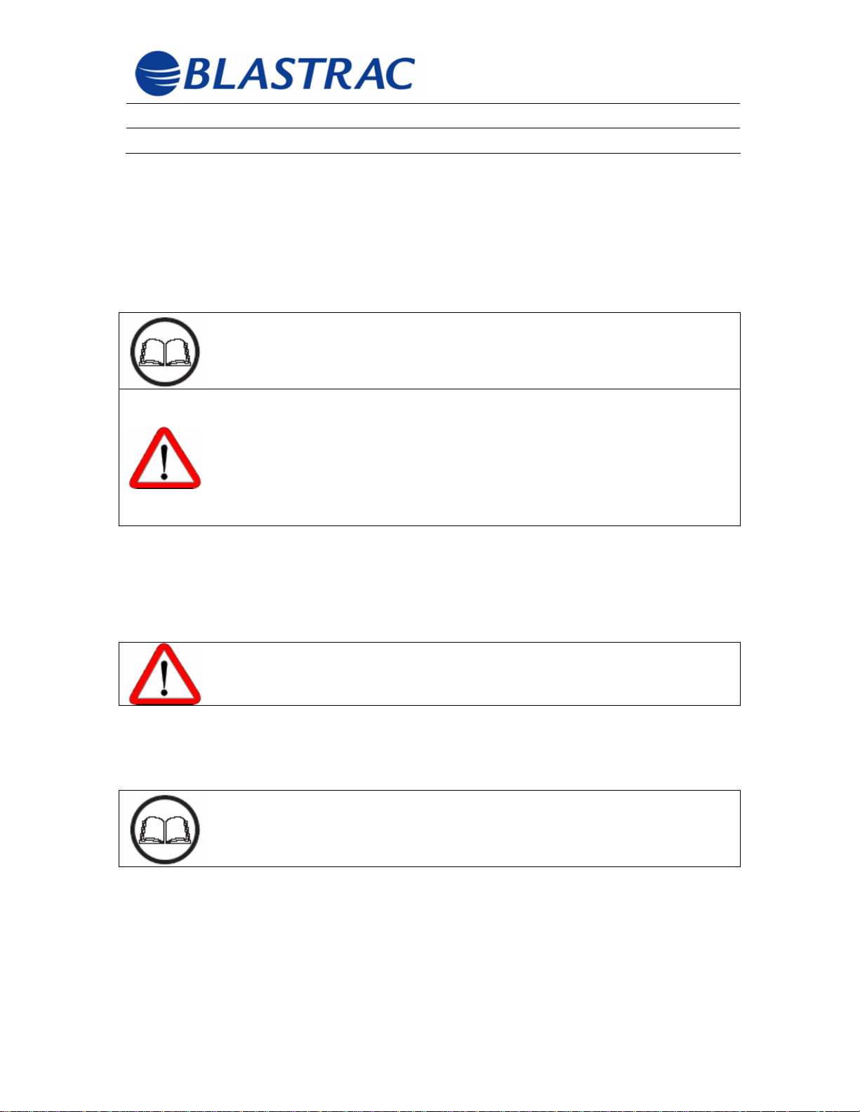
6.3 Recommended Scarifying Direction
1. Place the dust collector near the site power connection and place the
scarifier near the dust collector.
2. Unroll the dust collector hose and connect one end to the scarifier and
the other end to the dust collector.
3. Start both machines. For further details, see Section 5
“Preparation/Starting”
4. The scarifier should be driven in a “back-and-forth” direction, away
from the dust collector, as depicted in Figure 6.1.
To avoid damage to the dust collector hose, be aware of the
hose length and do not drive the scarifier out of the hose’s
range.
5. Finish by moving the dust collector and scarifying that area where the
dust collector was stationed.
1
2
3
Fig 6.1
1) Dust Collector
2) Dust Hose
3) Scarifier
©Blastrac February 2006
29
Page 31
Operating Instructions BMP-(G/E)250-X
Section 6 – Operation February 2006
6.4 What To Do When Faults Occur – Emergency Stop
In the event that any fault occurs, to the scarifier or the dust collector, an
emergency stop should be executed by pulling the Deadman Lanyard (See
Figure 3.3) away from the machine and both machines should be placed in
“Maintenance Mode”. See Section 1.7 “Maintenance Mode”.
All safety issues, instruction and cautions contained within this
manual should be complied with at all times. See Section 1
“Safety Precautions”.
In addition to these Manual instructions and cautions, all
statutory and other binding (law) accident prevention
regulations such as OSHA, state and/or local entity articles
should be a part of operator training. This type of obligation
may govern, i.e. handling of hazardous materials or wearing
personal safety equipment. Some of these are listed in the
Section 1.2 “Statutory Safety Considerations”.
Once an emergency stop has been executed and the machine is in the
“Maintenance Mode”, personnel may begin troubleshooting to determine the
cause of the fault. Both machines should stay in the “Maintenance Mode” until
the cause of the fault has been determined and corrected.
Important: Warning for Gasoline Machines! Prevent accidental
starting by removing spark plug wire when servicing, parking
or transporting equipment.
6.5 Restarting After Breakdowns
All safety issues, instructions and cautions contained within
this manual should be complied with at all times. See Section 1
“Safety Precautions”.
For restarting the machine after a breakdown or after any maintenance work,
See Section 5 “Preparation/Starting”
©Blastrac February 2006
30
Page 32

Operating Instructions BMP-(G/E)250-X
Section 6 – Operation February 2006
6.6 Measure to be Taken Before and After Storage
All safety issues, instruction and cautions contained with this manual
should be complied with at all time. See Section 1 “Safety
Precautions”.
Before Storing:
1. Switch the machine off. See Section 5.3 “Stopping/Switching Off”.
2. Protect electric motors against moisture, heat, dust and impact. If the
scarifier is equipped with a gasoline motor, please refer to the
enclosed owner’s manual for the motor).
3. Clean the machine and cover it with a plastic sheet or tarp.
After Storage:
1. Uncover machine and move the machine to an open area.
2. Clean the machine if necessary and perform all necessary regular
maintenance. See Section 7 “Maintenance).
3. For starting the machine see Section 5 “Preparation/Starting”.
©Blastrac February 2006
31
Page 33

Operating Instructions BMP-(G/E)250-X
Section 7 – Maintenance February 2006
Section 7
7.1 Information
7.2 Maintenance and Inspection List
7.3 Repairs
7.4 Scarifier Drum
7.5 Equipment for the Scarifier Drum
7.6 Replacing the Scarifier Drum
7.7 Influencing the Scarifying Pattern
7.8 Gear Belt
7.9 Motor
©Blastrac February 2006
32
Page 34
Operating Instructions BMP-(G/E)250-X
Section 7 – Maintenance February 2006
7.1 Information
Before beginning any repair or maintenance work on the
machine or its drive, ensue that it cannot be switched on
accidentally. Set the machine into “Maintenance Mode”. See
Section 1.7 “Maintenance Mode.
Breakdowns caused by insufficient and unprofessional
maintenance can lead to very high repair costs and long
downtimes. Regular maintenance and quality-trained
personnel are essential.
The machine’s service life, operational efficiency and safety depend on several
factors including proper and regularly scheduled maintenance.
The Maintenance and Inspection List I Section 7.2 contains
information on schedules, inspections, and maintenance for
normal operation. The schedule is based on daily use of the
machine. If the number of working hours shown here is not
reached in the corresponding period, the period may be
extended. However, a complete inspection must take place
every year.
Because operating conditions can vary considerably, it is not possible to state in
advance how often checks for wear, inspections, maintenance, and/or repairs are
necessary. A practical inspection schedule should be drawn up, taking the
operating conditions into account. Blastrac technicians are available to provide
more assistance in creating a practical schedule.
This manual’s operating, maintenance and safety instructions
must be complied with during maintenance and repair work. In
particular, instructions provided with electrical and gasoline engine
components must be complied with.
©Blastrac February 2006
33
Page 35
Operating Instructions BMP-(G/E)250-X
Section 7 – Maintenance February 2006
7.2 Maintenance and Inspection List
The following maintenance schedule should be strictly
followed to insure personnel safety, as well as proper
operation and efficiency.
12 hours after repairs:
• Check all safety devices for effectiveness.
• Check all accessible screw connections for correct fit and tightness.
Daily and before starting work:
• Check all power supply cable for damage.
• Check dust collector hose for damage.
• Verify that there is no foreign material in the scarifier drum.
• Verify that the dust container of the dust collector is empty.
• Check the scarifier durm, lateral axle, scarifier cutters and housing for
wear.
• Check the tension of the gear belt; tighten if necessary. See Section 7.8
“Gear Belt”.
Yearly:
• Full overhaul and cleaning of the complete machine.
If using a scarifying machine with a gasoline motor, always comply with the
enclosed owner’s manual for the motor.
7.3 Repairs
This Manual only describes repairs that occur during maintenance work or those
repairs that are required when replacing worn parts.
As with starting for the first time, we recommend that our
Blastrac personnel carry out the first repairs of all Blastrac
machines. This allows the equipment users operating and
maintaining the machine the opportunity to become extensively
familiar with the proper repair procedures.
©Blastrac February 2006
34
Page 36
Operating Instructions BMP-(G/E)250-X
Section 7 – Maintenance February 2006
7.3 Repairs (cont’d)
If for any reason the decision is made to replace parts, please
comply with the following instructions in this manual and
perform all work in the sequence shown.
Production losses are often more expensive than stocking
critical high wear parts. Consider maintaining an inventory of
critical high wear parts.
Any screws, nuts, or bolts removed must be replaced with the
same quality (strength, material) and design.
Before beginning any repair or maintenance work on the
machine or its drives, ensure that it cannot be switched on
accidentally. Set the machine into the “Maintenance Mode”.
See Section 1.7 “Maintenance Mode”
Use original Blastrac replacement parts only.
7.4 Scarifier Drum
The scarifier drum is a highly stressed component of the machine and special
attention should be paid to the drum during maintenance and repairs.
If the scarifier drum is replaced always clean and lubricate the drive shaft so that
the next time the drum is replaced rust or deposits of dirt do not make the
replacement more difficult. Reassemble using Dynatex Anti-Seize PN 49560 or
Loctite Anti-Seize PN 767.
If the scarifier drum must be dismantled for new parts to be installed or
components replaced, make sure that the arrangement of the scarifier cutters
and spacers is maintained as shown in the enclosed components drawings found
in Section 10 “Spare Parts”. In addition, make sure that the holes in the
covering plate for the lateral axles are not worn out and that the screws are tight.
©Blastrac February 2006
35
Page 37

Operating Instructions BMP-(G/E)250-X
Section 7 – Maintenance February 2006
7.5 Scarifier Drum (cont’d)
To obtain an even, clean surface profile on the surface to be scarified:
• Ensure that the correct scarifying depth is set.
• Ensure that the machine is being driven at the correct drive speed.
• Ensure that the correct components for the scarifier drum are being used.
• Ensure that the correct scarifier cutters for that specific surface are being
used.
Incorrectly installed scarifier drum will cause unbalanced
machine operation and excessive wear.
Incorrect assembly of OEM machine parts and components voids the
equipment warranty.
Use of non-OEM parts and cutters voids the equipment warranty.
7.6 Equipment for the Scarifier Drum
The examples of scarifier cutters enclosed within this manual have been
extensively tested by Blastrac technicians and display an even scarified pattern.
The selection of cutter types and the component arrangement are among the
most important factors for proper operation and efficiency of these machines.
An incorrect component arrangement for the scarifier drum
leads to extreme wear rates and reduces machine performance.
See Section 10 “Spare Part” for component mounting
diagrams.
©Blastrac February 2006
36
Page 38
Operating Instructions BMP-(G/E)250-X
Section 7 – Maintenance February 2006
7.6 Replacing the Scarifier Drum
Before beginning any repair or maintenance work on the
machine or its drives, ensure that it cannot be switched on
accidentally. Set the machine into the “Maintenance Mode”.
See Section 1.7 “Maintenance Mode”.
HOT! Friction caused by running this machine over any floor
causes heat to build up in the scarifier tools and the scarifier
drum. Use gloves when removing the scarifier drum to
prevent a burn injury.
Removal:
1) Unscrew the fastening screws from the side panel and remove panel
by pulling it away from the machine housing.
2) Pull the scarifier drum off of the drive shaft.
Installation
1) Clean the drive shaft and grease it evenly.
2) Slide the scarifier drum onto the drive shaft until it comes to a stop.
When fitting the side panel back on, make sure that the bearing unit is correctly
fitted into the side panel.
Never use any of these machines without the side panel and
protective guards correctly fitted and installed.
7.7 Influencing the Scarifying Pattern
The appropriate scarifying pattern depends o the surface being worked on and
can be influenced by varying the scarifying depth and the drive speed.
Depending on the surface to be scarified, selection of scarifier cutters, scarifying
depth and drive speed will vary. A correct selection can be obtained through trial
and error, preferably on an area of the surface that is not highly visible or
extremely important.
©Blastrac February 2006
37
Page 39
Operating Instructions BMP-(G/E)250-X
Section 7 – Maintenance February 2006
7.7 Influencing the Scarifying Pattern (cont’d)
After fitting new or different scarifier cutters onto the
machine, always check the scarifying pattern. This is the
only way to ensure operational efficiency and to protect
against unnecessary repair costs.
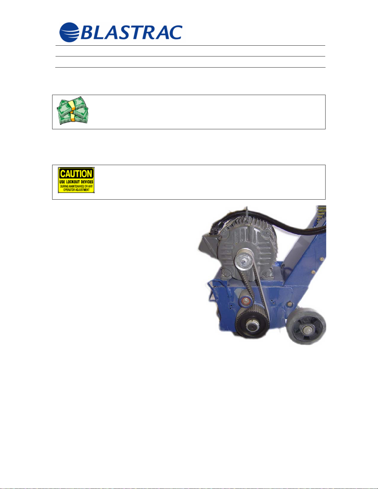
7.8 Gear Belt
Before beginning any repair or maintenance work on the
machine or its drives, ensure that it cannot be switched on
accidentally. Set the machine into the “Maintenance Mode”.
See Section 1.7 “Maintenance Mode”.
Removal:
• Remove the screws for the belt
guard and remove guard.
• If necessary, slacken the belt
tension by loosening the belt
tensioner (See Figure 7.1, item
#C) and remove the belt.
The gear belt is tensioned by means of
a tensioner, which can be loosened and
slid left or right.
Installation:
• Place the gear belt over the
motor pulley and drum pulley,
then move tensioner right to
tension the belt.
• Make sure that the gear belt is parallel and has the correct initial tension.
Depth of displacement should be about 3/16” when squeezing the belt by
hand as indicated by the double arrow “B” in Figure 7.1.
C
©Blastrac February 2006
38
Page 40

Operating Instructions BMP-(G/E)250-X
Section 8 - Electrical February 2006
Section 8
8.1 Circuit Diagrams
©Blastrac February 2006
39
Page 41
Operating Instructions BMP-(G/E)250-X
Section 8 - Electrical February 2006
8.1 Circuit Diagrams
To ensure operator and personnel safety, electrical power should
be completely removed or disconnected from the machine. Set the
machine into the “Maintenance Mode”. See Section 1.7
“Maintenance Mode”.
Work on the machine’s electrical equipment must only be carried
out by a qualified electrician or by trained personnel under the
guidance and supervision of a qualified electrician.
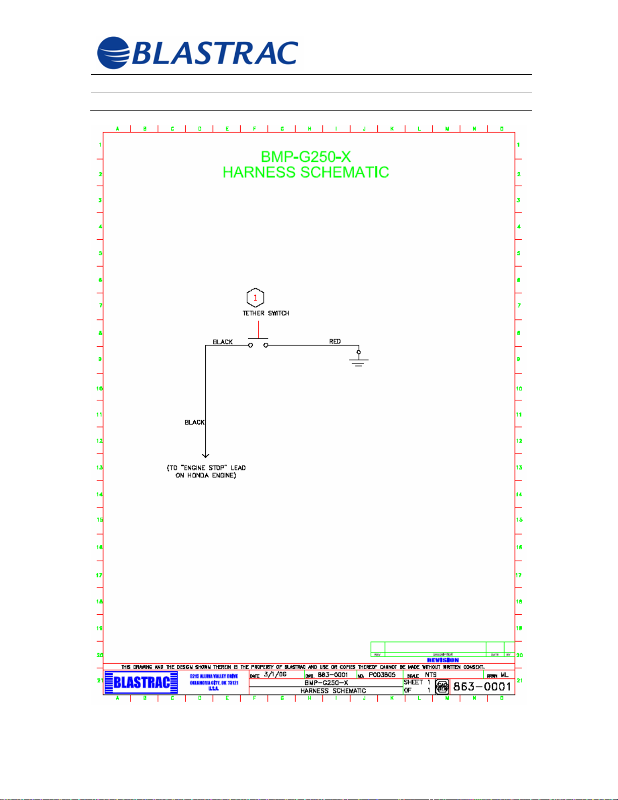
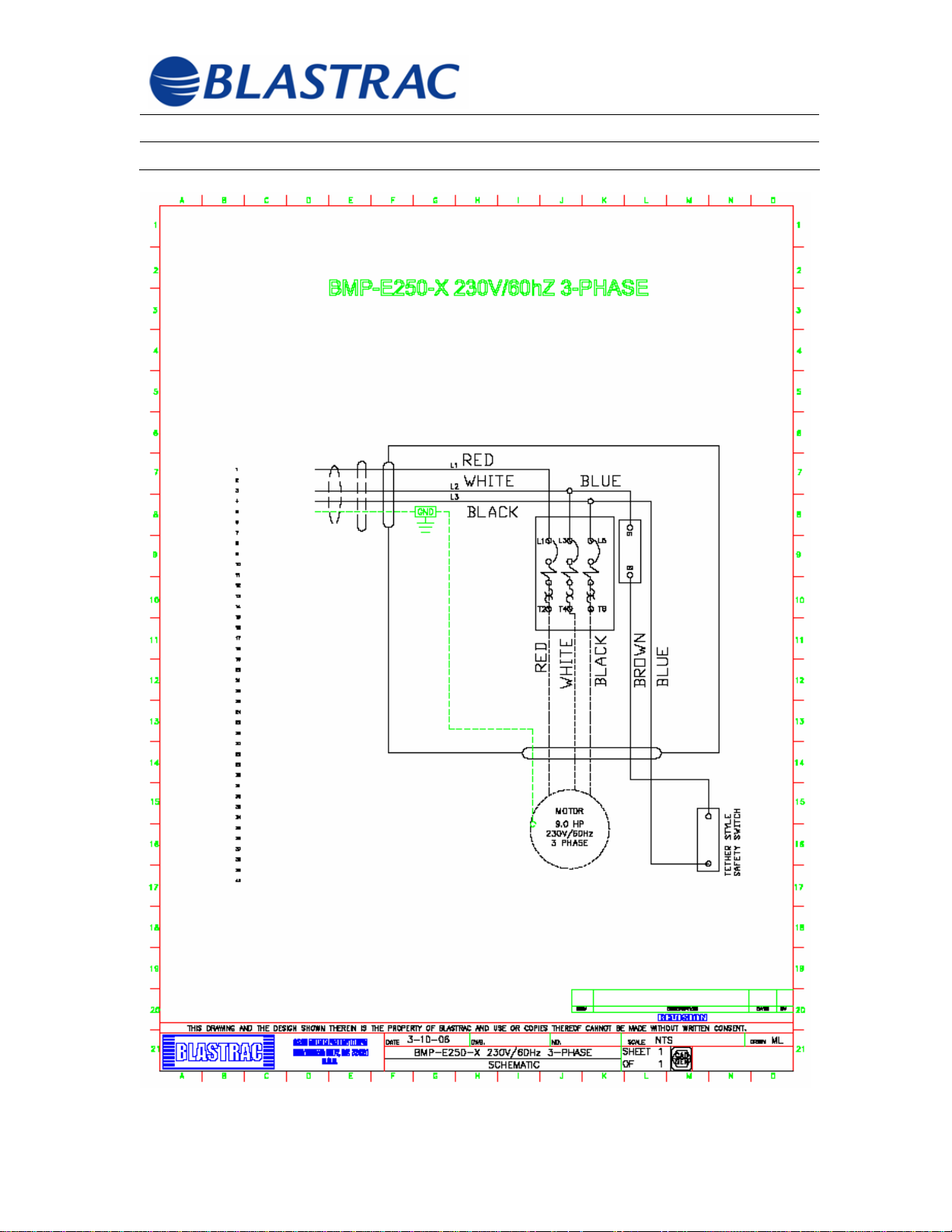
Order electrical items by referring to the circuit diagrams or by
contacting you Blastrac representative.
©Blastrac February 2006
40
Page 42
Operating Instructions BMP-(G/E)250-X
Section 8 - Electrical February 2006
©Blastrac February 2006
41
Page 43
Operating Instructions BMP-(G/E)250-X
Section 8 - Electrical February 2006
©Blastrac February 2006
42
Page 44

Operating Instructions BMP-(G/E)250-X
Section 9 - Troubleshooting February 2006
Section 9
9.1 Troubleshooting
©Blastrac February 2006
43
Page 45

Operating Instructions BMP-(G/E)250-X
Section 9 - Troubleshooting February 2006
Before beginning any repair or maintenance work on the
machine or its drives, ensure that it cannot be switched on
accidentally. Set the machine into the “Maintenance Mode”.
See Section 1.7 “Maintenance Mode”.
FAULT POSSIBLE CASUE REMEDIES
Excessive Vibration
Unusual noise Defective bearing
Controller cannot be
switched on
NOTE: Only a qualified
electrician should
troubleshoot the
machine
Motor does not start
NOTE: Only a qualified
electrician should
troubleshoot the
machine
Unbalanced drum
Defective bearing
Incorrect tension of gear
belt
Defective motor
Main power connection
not properly connected
Deadman lanyard not
correctly attached
Supply voltage under
voltage threshold
Electric – Motor fault
Internal Combustion
Motor
Replace worn and/or
broken scarifier cutters
Check drive shaft bearing
and replace if necessary
Check drive shaft bearing
and replace if necessary
Check gear belt tension
and alter if necessary
Replace motor
Check main connection
and switch on again
Check for proper
connection and switch on
again
Correct low voltage
problem or find alternate
power supply
If proper power is being
presented to the motor,
the motor windings are
open, shorted or
grounded and the motor
must be repaired or
replaced. Use only an
authorized motor shop to
repair motor
Refer to the enclosed
owner’s manual for motor
©Blastrac February 2006
44
Page 46

Operating Instructions BMP-(G/E)250-X
Section 10 – Spare Parts February 2006
Section 10
10.1 Spare Parts List
10.2 Assembly Plans
©Blastrac February 2006
45
Page 47

Operating Instructions BMP-(G/E)250-X
Section 10 – Spare Parts February 2006
3.1 Spare Parts List
Refer to the remainder of this section
3.2 Assembly Plans
Refer to the remainder of this section
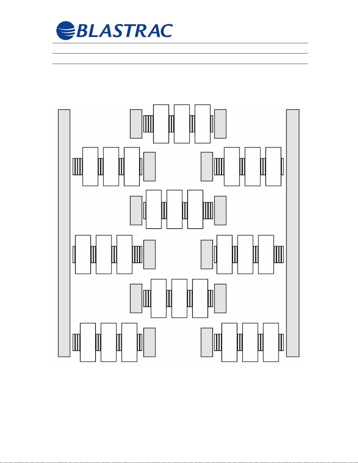
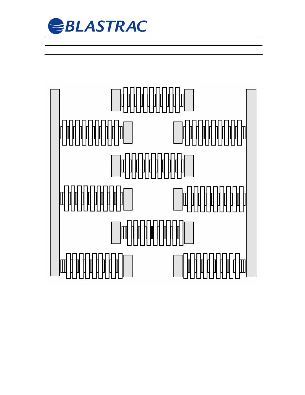
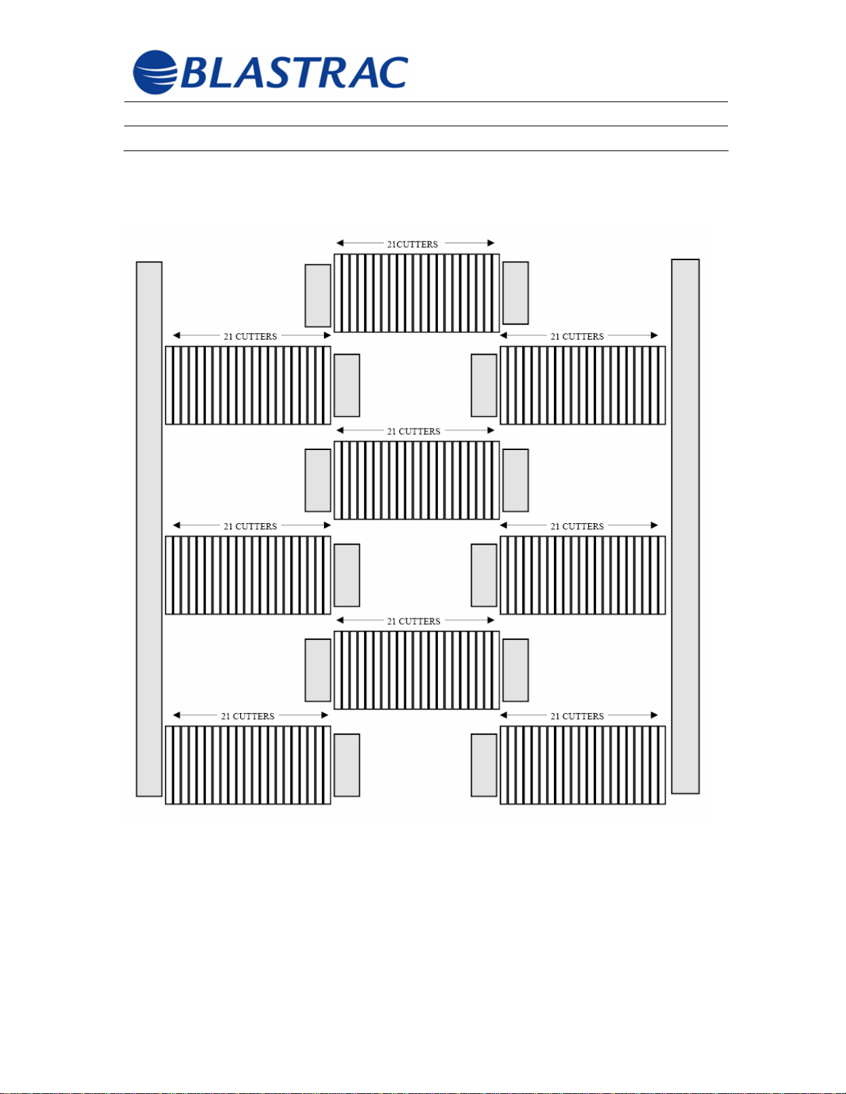
Use only sufficient scarifier cutters and spacers so that the
tools can still move freely (axial plan min. 1-3mm). To avoid an
unbalanced scarifier drum each shaft must have the same
number of cutters and spacers.
©Blastrac February 2006
46
Page 48
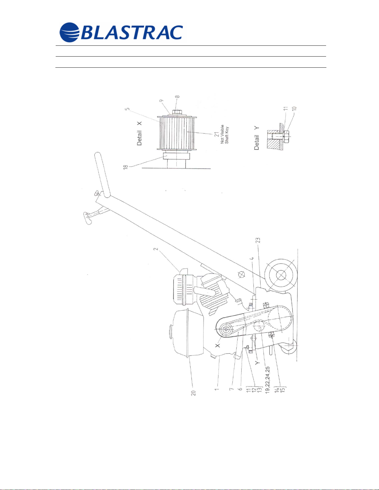
Operating Instructions BMP-(G/E)250-X
Section 10 – Spare Parts February 2006
PARTS FOR GAS ENGINE
©Blastrac February 2006
47
Page 49
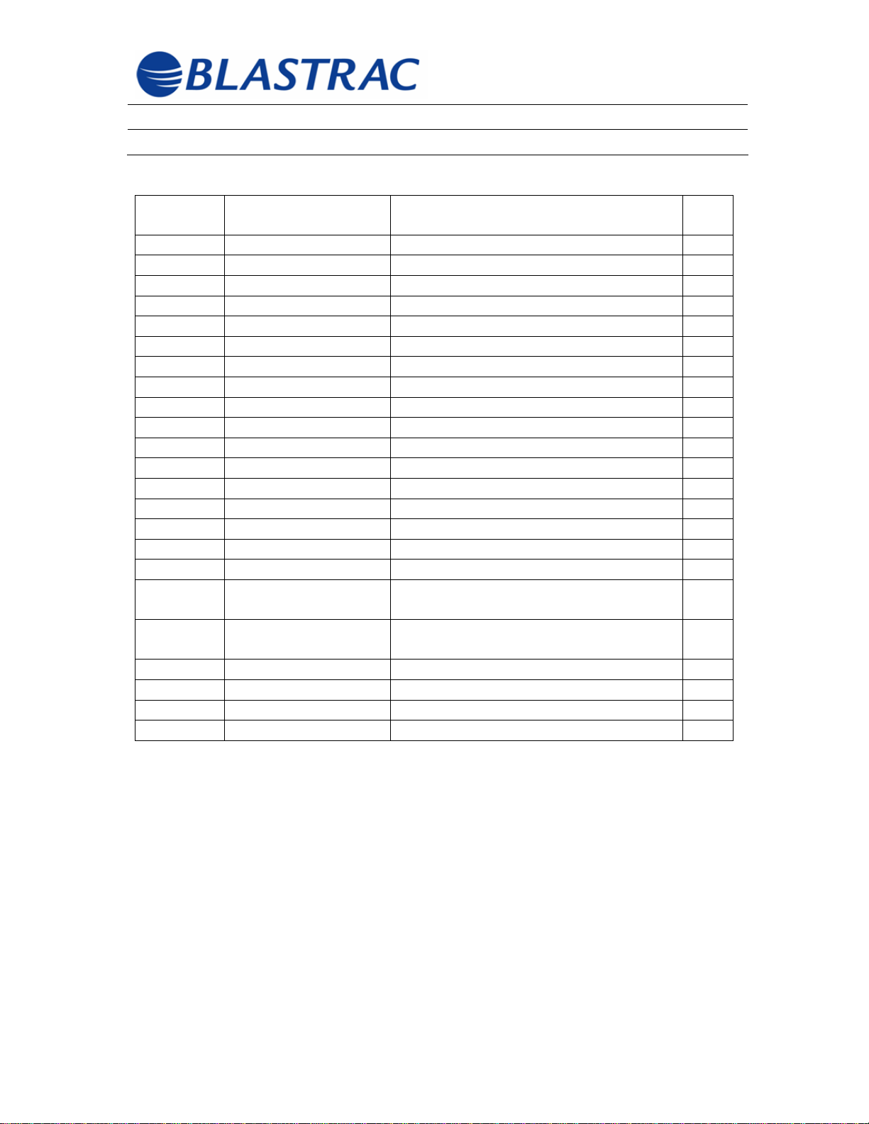
Operating Instructions BMP-(G/E)250-X
Section 10 – Spare Parts February 2006
PARTS FOR GAS ENGINE
ITEM
NUMBER
1 SS-999-702556 ENGINE, 9HP HONDA GX270 1
2 SS-999-701790 DEFLECTOR, MUFFLER 1
4 SS-999-795.00.75 PLATE/SOLID ENGINE MOUNT 1
5 SS-999-701534 PULLEY/UPPER TOOTED 1
6 SS-999-109376 BELT/TOOTHED 880 1
7 SS-999-706111 GUARD/BELT 1
8 SS-999-110370 SCREW/HEX 7/16UNF X 1 ¼” 1
9 SS-999-108552 WASHER/FLAT 13/30 X 1.6 1
10 SS-999-100614 SCREW/HEX M10 X 20 4
11 SS-999-104715 WASHER/LOCK M10 8
12 SS-999-108541 WASHER/FLAT 10.5/20 X 2 4
13 SS-999-101609 SCREW/HEX M10 X 35 4
14 SS-999-101599 SCREW/HEX M8 X 16 2
15 SS-999-100618 WASHER/LOCK M8 3
16 SS-999-706364 SWITCH/DEADMAN 1
18 SS-999-701532 SPACER/DISTANCE 1
19 SS-999-702473 PULLEY/TENSIONING 1
20 SS-999-
21 SS-99922 SS-999-702468 SPACER/TENSIONING PULLEY 1
23 SS-999-702346 HOUSING 1
24 SS-999-702469 BAR/RETAINING 1
25 SS-999-107870 SCREW/HEX M12 X 90 1
PART NUMBER DESCRIPTION QTY
TANK/FUEL GX270 1
HON.3690070
KEY/DRIVE SHAFT 1
HON.2027167
©Blastrac February 2006
48
Page 50
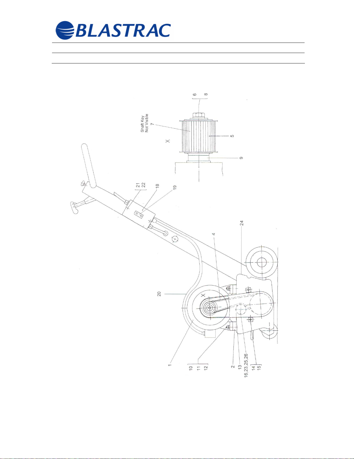
Operating Instructions BMP-(G/E)250-X
Section 10 – Spare Parts February 2006
PARTS FOR ELECTRIC MOTOR
230V, 3-PHASE, 60 Hz
©Blastrac February 2006
49
Page 51

Operating Instructions BMP-(G/E)250-X
Section 10 – Spare Parts February 2006
PARTS FOR ELECTRIC MOTOR
230V, 3-PHASE, 60 Hz
ITEM
NUMBER
1 SS-999-109446 MOTOR/ELECTRIC 3-PHASE 1
2 SS-999-795.00.75 PLATE/SOLID ENGINE MOUNT 1
4 SS-999-702559 BELT/TOOTHED 840 1
5 SS-999-701535 PULLEY/UPPER TOOTHED 1
6 SS-999-110370 SCREW/HEX 7/16 UNT X 1 ½” 1
7 KEY/SHAFT ¼” X ¼” X 1.75” 1
8 SS-999-108551 WASHER/FLAT 13.0/30 X 3 1
9 SS-999-628.00.52 SPACER/DISTANCE 1
10 SS-999-101608 SCREW/HEX M10 X 30 1
11 SS-999-104715 WASHER/LOCK M10 1
12 SS-999-108541 WASHER/FLAT 10.5/21 X 2 1
13 SS-999-702377 GUARD/BELT 1
14 SS-999-101598 SCREW/HEX M8 X 12 1
15 SS-999-100618 WASHER/LOCK M8 1
16 SS-999-702473 PULLEY/TIGHTENING 1
17 SS-999-706364 SWITCH/DEADMAN 1
18 SS-999-MCC.25.KAZ BOX/SWITCH ENCLOSURE 1
19 SS-999-MCC.25.10A SWITCH/10AMP 1
20 SS-999-
21 SS-99922 SS-99923 SS-999-702468 SPACER/BELT TENSIONING
24 SS-999-702346 HOUSING 1
25 SS-999-702469 BAR/RETAINING 1
26 SS-999-107870 SCREW/HEX M12 X 90 1
PART NUMBER DESCRIPTION QTY
COR/12/4 POWER 6
AIW.12X4CRD
MODULE/SHUNT RELAY 440V 1
MCC.25AA440
MODULE/SHUNT RELAY 220V 1
MCC.25AA220
1
PULLEY
©Blastrac February 2006
50
Page 52
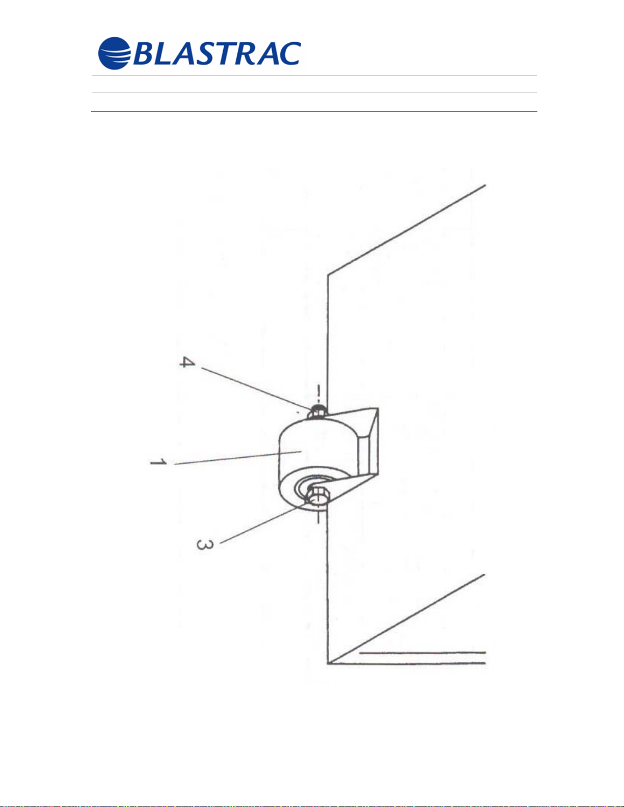
Operating Instructions BMP-(G/E)250-X
Section 10 – Spare Parts February 2006
FRONT CASTER ASSEMBLY
©Blastrac February 2006
51
Page 53
Operating Instructions BMP-(G/E)250-X
Section 10 – Spare Parts February 2006
FRONT CASTER ASSEMBLY
ITEM
NUMBER
1 SS-999-109377 WHEE/FRONT COMPLETE 1
2 N/A BUSHING/FLANGED 2pc 2
3 SS-999-107870 SCREW/HEX M12 X 90 1
4 N/A NUT/HEX SELF LOCKING M12 1
PART NUMBER DESCRIPTION QTY
©Blastrac February 2006
52
Page 54
Operating Instructions BMP-(G/E)250-X
Section 10 – Spare Parts February 2006
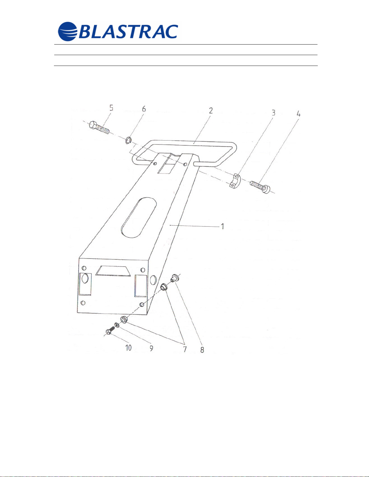
CHASSIS ASSEMBLY
©Blastrac February 2006
53
Page 55
Operating Instructions BMP-(G/E)250-X
Section 10 – Spare Parts February 2006
CHASSIS ASSEMBLY
ITEM
NUMBER
1 SS-999-706106 CHASSIS 1
2 SS-999-703006 HANDLE/BOW 1
3 SS-999-702636 RING/CLAMPING 2
4 SS-999-103175 SCREW/ALLEN M8 X 25 2
5 SS-999-107938 SCREW/HEX M8 X 40 2
6 SS-999-100618 WASHER/LOCK M8 2
7 SS-999-702624 MOUNT/RUBBER 8
8 SS-999-702625 SLEEVE/CLAMPING 4
9 SS-999-104715 WASHER/LOCK M10 4
10 SS-999-100614 SCREW/HEX M10 X 20 4
PART NUMBER DESCRIPTION QTY
©Blastrac February 2006
54
Page 56
Operating Instructions BMP-(G/E)250-X
Section 10 – Spare Parts February 2006
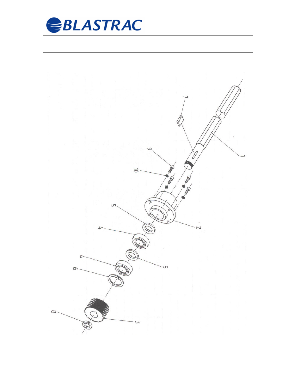
DRIVE SHAFT ASSEMBLY
©Blastrac February 2006
55
Page 57
Operating Instructions BMP-(G/E)250-X
Section 10 – Spare Parts February 2006
DRIVE SHAFT ASSEMBLY
ITEM
NUMBER
SS-999-706130 SHAFT/HEX DRIVE ASSEMBLED
1 SS-999-702451 SHAFT/HEX DRIVE 1
2 SS-999-702452 HOUSING/BEARING 1
3 SS-999-702347 PULLEY/LOWER TOOTHED 1
4 SS-999-108265 BEARING/DRIVESIDE 6207 RS1 2
5 SS-999-702456 RING/SPACER 2
6 SS-999-108727 RING/RETAINING 72 X 2.5 1
7 SS-999-107974 KEY/HEX SHAFT 10 X 8 X 45 1
8 SS-999-108750 NUT/SHAFT M35 X 1.5 1
9 SS-999-100598 SCREW/ALLEN M8 X 20 4
10 SS-999-102286 WASHER/SAFETY M8 4
PART NUMBER DESCRIPTION QTY
©Blastrac February 2006
56
Page 58
Operating Instructions BMP-(G/E)250-X
Section 10 – Spare Parts February 2006
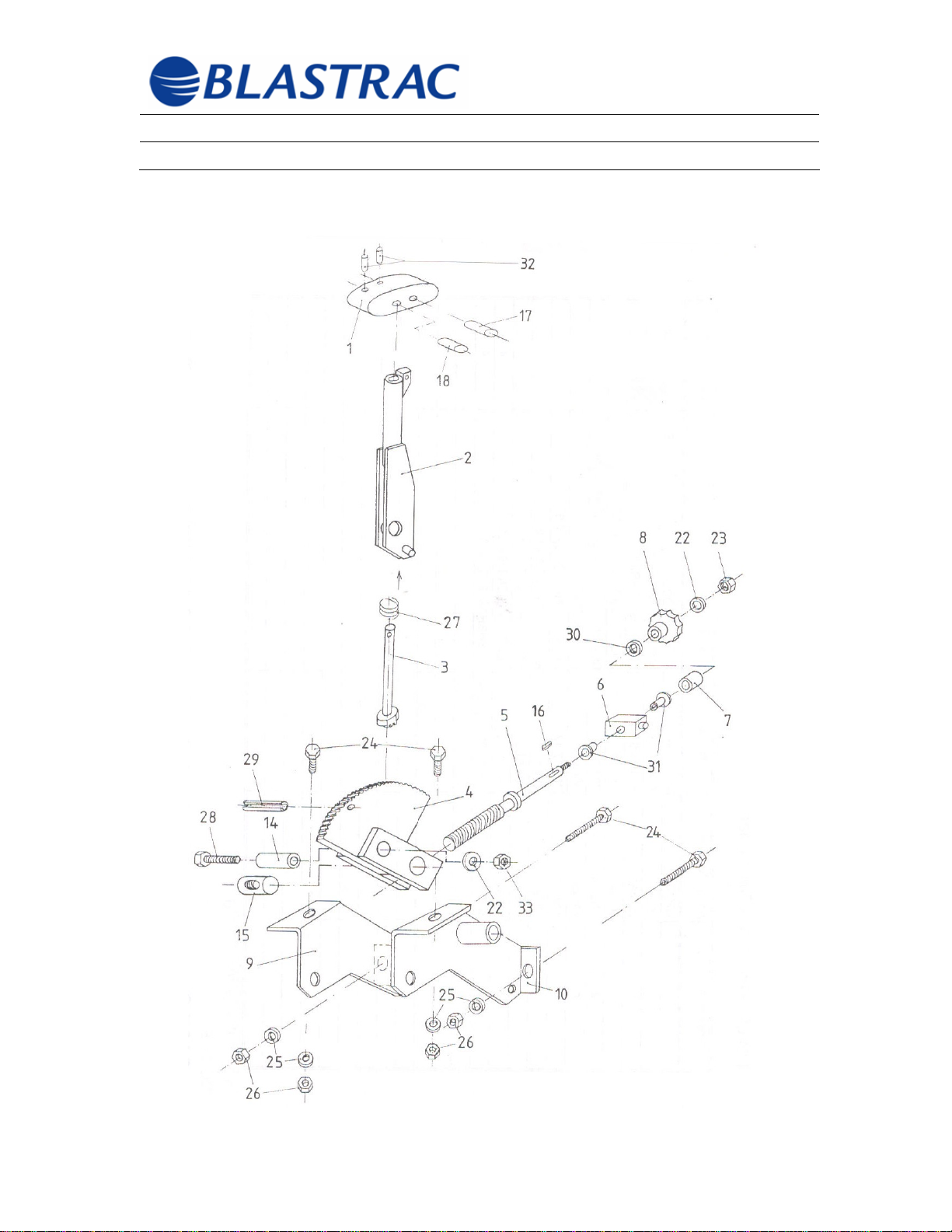
DEPTH ADJUSTER ASSEMBLY
©Blastrac February 2006
57
Page 59

Operating Instructions BMP-(G/E)250-X
Section 10 – Spare Parts February 2006
DEPTH ADJUSTER ASSEMBLY
ITEM
NUMBER
ASSEMBLY/DEPTH CONTROL
1 SS-999-706114 HANDLE/DEPTH CONTROL 1
2 SS-999-702360 LEVER/ADJUSTING 1
3 SS-999-703012 ROD/DEPTH ADJUSTING LEVER 1
4 SS-999-702359 ELEMENT/TOOTHED 1
5 SS-999-702361 SPINDLE/ADJUSING 1
6 SS-999-702355 PART/SQUARE 1
7 SS-999-703016 BUSHING 1
8 SS-999-703017 GRIP/ADJUSMENT STAR 1
9 SS-999-706109 PROFILE/BEVELED RIGHT 1
10 SS-999-706108 PROFILE/BEVELED LEFT 1
14 SS-999-702354 BUSHING BRASS 1
15 SS-999-702356 DRIVER 1
16 SS-999-107990 KEY/DEPTH ADJUST SPINDLE 4 X 4
17 SS-999-113453 PIN/CYLINDER M8 X 40 1
18 SS-999-114626 PIN/CYLINDER M6 X 40 1
22 SS-999-101670 WASHER/FLAT 8.4/16 X 1.6 2
23 SS-999-100263 NUT/ACORN M8 1
24 SS-999-102332 SCREW/HEX M6 X 16 4
25 SS-999-100302 WASHER/LOCK M6
26 SS-999-102334 NUT/HEX M8 X 50
27 SS-999-701637 SPRING/PRESSURE 1
28 SS-999-107940 SCREW/HEX M8 X 50 1
29 SS-999-110455 ROOPIN/M6 X 28 1
30 SS-999-110537 SPRING/SAUCER 28 X 10.2 X 1.25 1
31 SS-999-110386 BEARIN/GLACIER MB 2215 DU 2
32 SS-999-107973 PIN/ROLL 2
33 SS-999-792.61.27 NUT/NYLON LOCK M8 1
PART NUMBER DESCRIPTION QTY
COMPLETE
1
16
©Blastrac February 2006
58
Page 60
Operating Instructions BMP-(G/E)250-X
Section 10 – Spare Parts February 2006
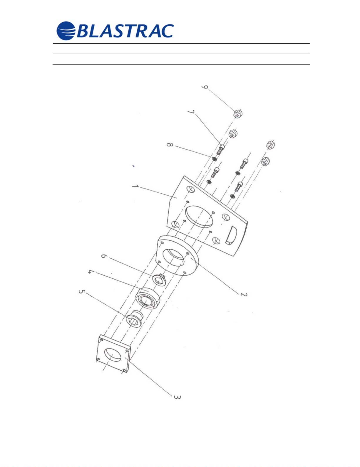
HOUSING ENDPLATE ASSEMBLY
©Blastrac February 2006
59
Page 61
Operating Instructions BMP-(G/E)250-X
Section 10 – Spare Parts February 2006
HOUSING ENDPLATE ASSEMBLY
ITEM
NUMBER
SS-999-706131 COVER/ASSEMBLED HOUSING
1 SS-999-706112 COVER/HOUSING 1
2 SS-999-702454 FLANGE/BEARING 1
3 SS-999-702453 WASHER/CLAMP 1
4 SS-999-108268 BEARING/SEALED 6210 2 RS 1
5 SS-999-701569 BUSH/DRIVING 1
6 SS-999-108721 RING/SAFETY M50 X 2 1
7 SS-999-105942 SCREW/ALLEN M8 X 30 4
8 SS-999-100618 WASHER/LOCK M8 4
9 SS-999-702466 NUT/TAPERED HEX M10 4
PART NUMBER DESCRIPTION QTY
©Blastrac February 2006
60
Page 62
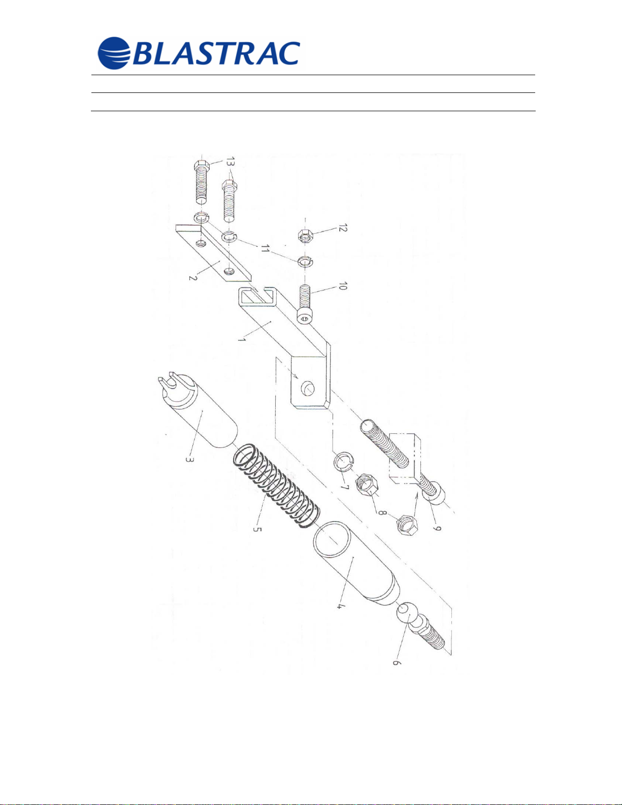
Operating Instructions BMP-(G/E)250-X
Section 10 – Spare Parts February 2006
SPRING ASSEMBLY
©Blastrac February 2006
61
Page 63
Operating Instructions BMP-(G/E)250-X
Section 10 – Spare Parts February 2006
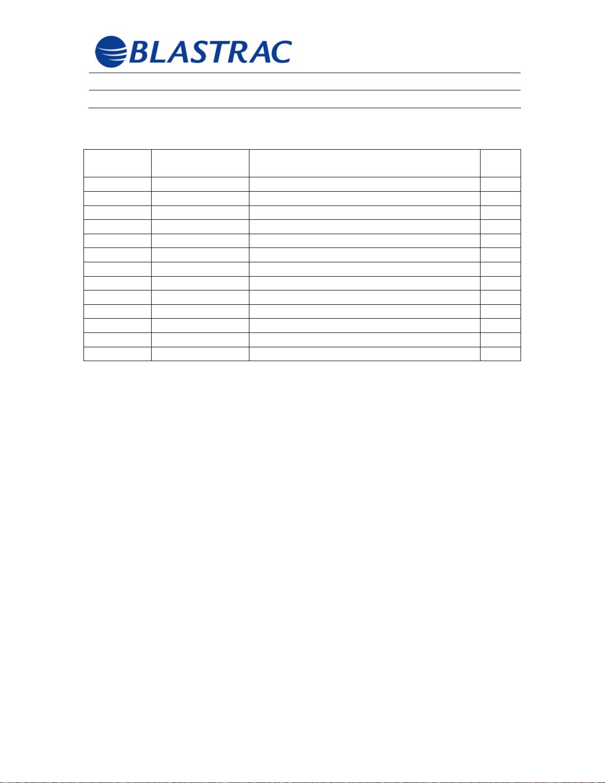
SPRING ASSEMBLY
ITEM
NUMBER
1 SS-999-702364 PROFILE/ADJUSTMEN 2
2 SS-999-703025 BRACKET 2
3 SS-999-702363 TUBE/LOWER SPRING 2
4 SS-999-702362 TUBE/UPPER SPRING 2
5 SS-999-706110 SPRING/COMPRESSION 2
6 SS-999-110390 PIVOT/BALL M16 2
7 SS-999-104715 WASHER/LOCK M10 2
8 SS-999-102287 NUT/HEX M10 4
9 SS-999-110284 SCREW/ALLEN M10 X 100 2
10 SS-999-101595 SCREW/ALLEN M8 X 10 2
11 SS-999-100618 WASHER/LOCK M8 6
12 SS-999-101822 NUT/HEX M8 2
13 SS-999-101599 SCREW/HEX M8 X 16 4
PART NUMBER DESCRIPTION QTY
©Blastrac February 2006
62
Page 64
Operating Instructions BMP-(G/E)250-X
Section 10 – Spare Parts February 2006
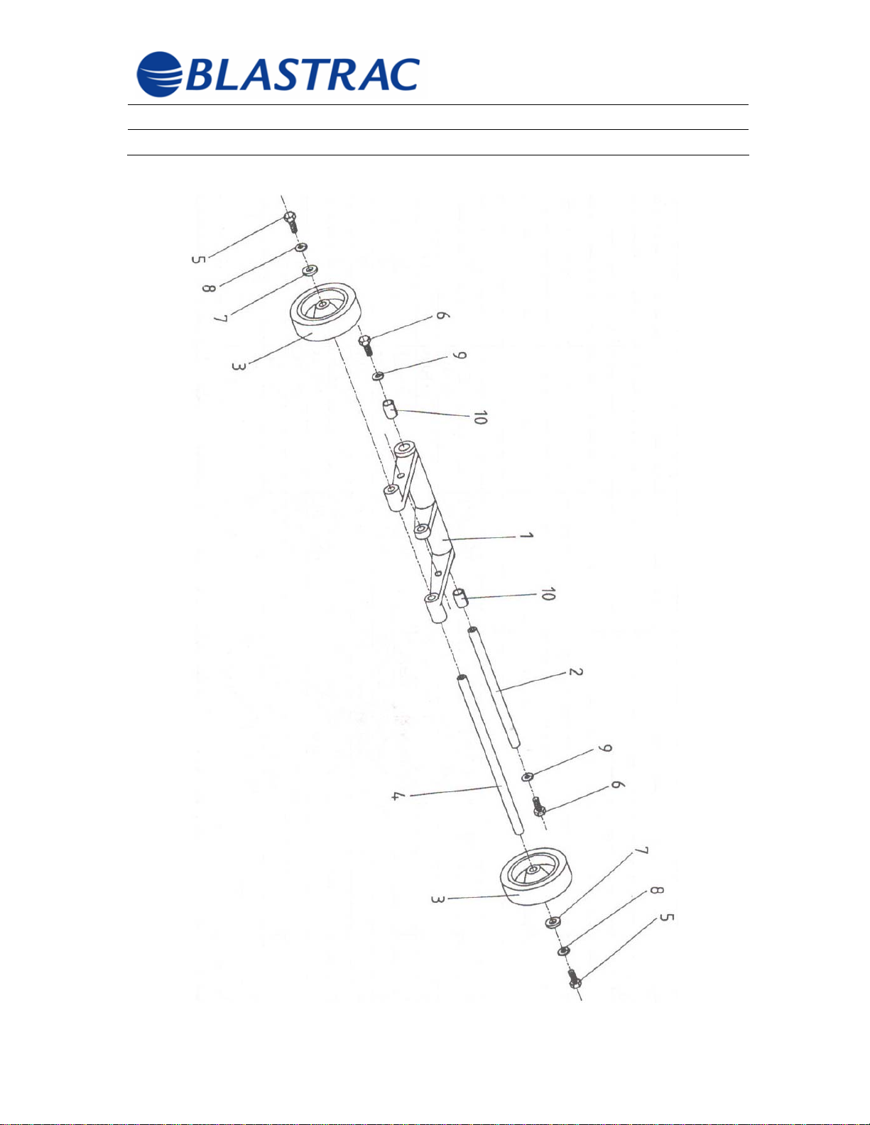
REAR CASTER ASSEMBLY
©Blastrac February 2006
63
Page 65
Operating Instructions BMP-(G/E)250-X
Section 10 – Spare Parts February 2006
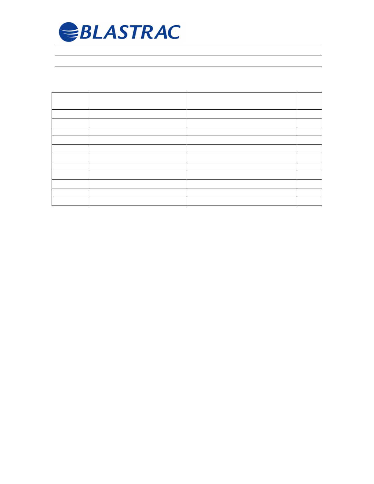
REAR CASTER ASSEMBLY
ITEM
NUMBER
SS-999-702521 BRACKET/AXLE ASSEMBLED
1 SS-999-702457 BRACKET/AXLE 1
2 SS-999-702458 AXLE 1
3 SS-999-109452 WHEEL/ELASTIC 2
4 SS-999-702459 AXLE/WHEEL 1
5 SS-999-101600 SCREW/HEX M8 X 20 2
6 SS-999-101608 SCREW/HEX M10 X 30 2
7 SS-999-108581 WASHER M8.4 X 35 X 2.5 2
8 SS-999-100618 WASHER/LOCK M8 2
9 SS-999-104715 WASHER/LOCK M10 2
10 SS-999-108481 BUSHING/MB 1620 DU 2
PART NUMBER DESCRIPTION QTY
©Blastrac February 2006
64
Page 66
Operating Instructions BMP-(G/E)250-X
Section 10 – Spare Parts February 2006
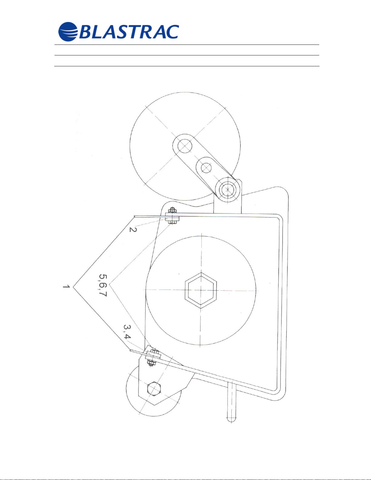
DUST SHIELD ASSEMBLY
©Blastrac February 2006
65
Page 67

Operating Instructions BMP-(G/E)250-X
Section 10 – Spare Parts February 2006
DUST SHIELD ASSEMBLY
ITEM
NUMBER
1 SS-999-706756 SHIELD/DUST SET 1
2 SS-999-702460 BAR/REAR DUST SHIELD CLAMPING 1
3 SS-999-702462 BAR/FRONT DUST SHIELD CLAMPING
4 SS-999-702463 BAR/FRONT DUST SHIELD CLAMPING
5 SS-999-104267 SCREW/HEX M6 X 20 8
6 SS-999-102334 WASHER/LOCK M6 X .8 8
7 SS-999-100302 NUT/HEX M6 8
PART NUMBER DESCRIPTION QTY
(RIGHT)
(LEFT)
1
1
©Blastrac February 2006
66
Page 68
Operating Instructions BMP-(G/E)250-X
Section 10 – Spare Parts February 2006
6 Point Medium Milling Cutters
Theoretical Assembly
27 cutters, 81 spacers
©Blastrac February 2006
67
Page 69
Operating Instructions BMP-(G/E)250-X
Section 10 – Spare Parts February 2006
8 Point Medium Tungsten Cutters
Theoretical Assembly
81 cutters, 108 spacers
©Blastrac February 2006
68
Page 70
Operating Instructions BMP-(G/E)250-X
Section 10 – Spare Parts February 2006
18 Point Large Star Cutters
Theoretical Assembly
189 cutters
©Blastrac February 2006
69
 Loading...