

Page 1
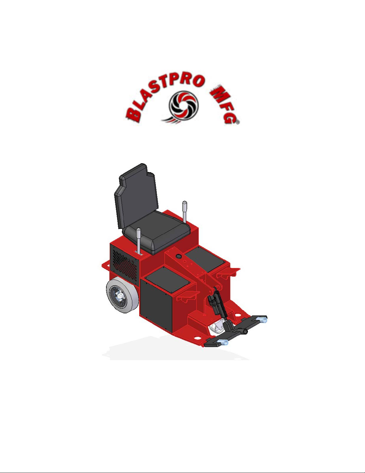
BRB-1500
MACHINE MANUAL
Page 2

Table of Contents
SECTION 1.1: APPLICATIONS...........................................................................4
SECTION 1.2: SPECIFICATIONS.......................................................................4
SECTION 1.3: MANUFACTURER.......................................................................4
SECTION 2.1: GENERAL....................................................................................6
SECTION 2.2: MAINTENANCE AND WEAR PART REPLACEMENT MODES ..6
SECTION 2.3: WORK SITE ASSESSMENT AND INSPECTION........................7
SECTION 2.4: PERSONAL PROTECTIVE EQUIPMENT (PPE).........................9
SECTION 2.5: OPERATIONAL SAFETY.............................................................9
SECTION 3.1: START-UP.................................................................................11
FIGURE 3.1.1..............................................................................................12
SECTION 3.2: SHUT DOWN.............................................................................12
SECTION 3.3: BLADE SELECTION..................................................................13
FIGURE 3.3.1..............................................................................................13
FIGURE 3.3.2..............................................................................................13
FIGURE 3.3.3..............................................................................................14
SECTION 3.4: TRANSPORT.............................................................................14
FIGURE 3.4.1..............................................................................................14
SECTION 4.1: MAINTENANCE INTERVALS....................................................17
SECTION 4.2: TROUBLESHOOTING...............................................................18
SECTION 4.3: MOTOR CONTROLLER FAULT CODES..................................19
SECTION 4.4: BATTERY CHARGING..............................................................20
SECTION 4.5: RECOMMENDED SPARE PARTS............................................21
SECTION 4.6: RECOMMENDED TOOLS.........................................................21
SECTION 4.7: PARTS LIST ..............................................................................22
Page 3

MACHINE MANUAL BRB-1500
SPECIFICATIONS
SECTION 1.1: APPLICATIONS
SECTION 1.2: SPECIFICATIONS
SECTION 1.3: MANUFACTURER
3
© 2013 Blastpro Manufacturing Inc. ®
Page 4

MACHINE MANUAL BRB-1500
SPECIFICATIONS
SECTION 1.1: APPLICATIONS
The BRB-1500 is specifically designed to remove coatings and coverings from
horizontal surfaces. Coatings may include glue, epoxies and cementitious
overlays. Coverings may include carpet, ceramic tile, and VCT.
A wide variety of tools are available from Blastpro® for your specific application.
In general, the BRB-1500 uses sharpened spring steel blades along with the
weight of the machine itself to perform the scraping function. The variable angle
of attack allows for a great deal of flexibility when dealing with different floor
coatings.
SECTION 1.2: SPECIFICATIONS
Dimensions (L x W x H) 30.25” x 31.75” x 52”
Weight 1580 lbs
Charge capacity Up to 8 hour run time
Electrical System 48 VDC, 48 VAC and 12 VDC
Blade Actuation Electric-over-hydraulic
Steering Electric
Ground Drive Electric
Blade Widths 2” through 24”
SECTION 1.3: MANUFACTURER
Blastpro Manufacturing
6021 Melrose Lane
Oklahoma City, OK 73127
Toll free: 877-495-6464
Phone: 405-491-6464
Fax: 405-495-4994
Website: www.BlastProMfg.com
4
© 2013 Blastpro Manufacturing Inc. ®
Page 5

MACHINE MANUAL BRB-1500
SAFETY
SECTION 2.1: GENERAL
SECTION 2.2: MAINTENANCE AND WEAR PARTS REPLACEMENT MODES
SECTION 2.3: WORK SITE ASSESSMENT AND INSPECTION
SECTION 2.4: PERSONAL PROTECTIVE EQUIPMENT
SECTION 2.5: OPERATIONAL SAFETY
5
© 2013 Blastpro Manufacturing Inc. ®
Page 6

MACHINE MANUAL BRB-1500
SAFETY
SECTION 2.1: GENERAL
Read and understand this Machine Manual prior to operating or performing
maintenance on the BRB-1500.
This Machine Manual has been developed as a guideline for machine operation.
It is not a substitute for proper organizational training and management.
All machine operators and maintenance personnel should be properly trained in
operation and safety features of the BRB-1500.
Make these operating instructions accessible to all operating and maintenance
personnel.
Never weld, modify, cut or grind components of the BRB-1500 without prior
written consent from the manufacturer.
Never use aggressive cleaning chemicals to clean the machine.
SECTION 2.2: MAINTENANCE AND WEAR PART REPLACEMENT MODES
Maintenance mode is defined as placing the machine in a configuration, which
minimizes potential electric, hydraulic or stored energy hazards.
In general, the machine should be placed in Maintenance Mode prior to
performing any maintenance and/or troubleshooting activities.
MAINTENANCE MODE:
1. Move the machine to a level surface.
2. Lower blade.
3. Move brake switch to “ON” position.
4. Depress E-stop button.
5. Block wheels to prevent the machine from moving.
6. Allow all components to cool prior to carrying out any maintenance work.
6
© 2013 Blastpro Manufacturing Inc. ®
Page 7

MACHINE MANUAL BRB-1500
SAFETY
In general, the machine should be placed in Wear Parts Replacement Mode prior
to changing the blade(s).
WEAR PARTS REPLACEMENT MODE:
1. Move the machine to a level surface.
2. Raise the blade holder so the blade is off of the ground.
3. Move brake switch to “ON” position.
4. Depress E-stop button
5. Loosen appropriate bolts and replace blade(s).
After performing any maintenance or repair work verify that all safety labels,
guards, lids and bolted connections are properly and securely installed on the
machine.
SECTION 2.3: WORK SITE ASSESSMENT AND INSPECTION
Before starting scraping operations, a site assessment must be performed.
During the site assessment verify the following:
Work area is flat, clean, and dry, free of debris, frost-free, and has no
flammable liquids nearby. Also, make sure that the machine will be able
to clear all obstructions. NEVER SCRAPE OVER BOLTS, NUTS,
SCREWS, NAILS, OR OTHER DEBRIS AS THIS MAY RESULT IN
SIGNIFICANT DAMAGE TO THE MACHINE AND SERIOUS INJURY TO
THE OPERATOR.
FLOORS HAVE BEEN THOROUGLY INSPECTED. SOME FLOOR OR
DECK SURFACES MAY BE COATED WITH, OR CONTAMINATED BY,
DANGEROUS MATERIALS SUCH AS:
o PCBs
o LEAD
o ASBESTOS
o PESTICIDES
o SOLVENTS
o CLEANING FLUIDS
o AND/OR OTHER HARMFUL CHEMICAL S
DISTURBING SUCH SURFACES CAN CREATE A SERIOUS HEALTH
THREAT TO THOSE WHO INHALE OR COME INTO CONTACT WITH
THE DUST. THE WORK AREA MUST BE CHECKED FOR THESE
MATERIALS BEFORE WORK CAN BEGIN. BLASTPRO
MANUFACTURING, INC. DOES NOT WARRANT ITS EQUIPMENT TO
BE SUITABLE FOR, OR APPROVED FOR, REMOVING DANGEROUS
7
© 2013 Blastpro Manufacturing Inc. ®
Page 8

MACHINE MANUAL BRB-1500
SAFETY
MATERIALS. IT IS THEREFORE THE RESPONSIBILITY OF THE
CONTRACTOR TO CONFIRM THE SAFETY OF THE WORK AREA
AND THE EQUIPMENT WITH THE PROPER AUTHORITIES. IT IS
ALSO THE RESPONSIBILITY OF THE CONTRACTOR TO WARN ALL
STAFF MEMBERS OF ALL THE POTENTIAL SHORT-TERM AND
LONG-TERM HEALTH RISKS ASSOCIATED WITH INHALING AND
COMING INTO CONTACT WITH DANGEROUS MATERIALS. THE
CONTRACTOR IS RESPONSIBLE FOR PROTECTING ALL WORKERS
FROM BEING EXPOSED TO DANGEROUS MATERIALS.
Operator and any other personnel in the work area are wearing safety
glasses with side shields, dust masks, ear plugs, hard hats, steel toed
work boots, long sleeved shirts, tight fitting clothing, and gloves. It is also
imperative for staff to tie back long hair and to remove all jewelry.
Work area has been blocked off to pedestrians, unprotected personnel,
and untrained personnel. In the event pedestrians, unprotected
personnel, or untrained personnel enter the work area, scraping
operations are to be stopped immediately.
Fire extinguishers are nearby. Also, take note of the location and the
contact information of fire departments close to the work site.
All guards are properly installed and in good working order prior to using
the machine.
All glass and equipment, including vehicles, are protected from debris.
This can be done by loosely hanging a sheet of visqueen or other
protective material in front of the glass or equipment in a curtain-like
fashion.
The operator must be aware of their surroundings and use common
sense. THE OPERATOR IS NOT TO OPERATE THE EQUIPMENT IF
HE IS TIRED, DISTRACTED, OR UNDER THE INFLUENCE OF
DRUGS, ALCOHOL, OR MEDICATION THAT DECREASES
AWARENESS.
8
© 2013 Blastpro Manufacturing Inc. ®
Page 9

MACHINE MANUAL BRB-1500
SAFETY
SECTION 2.4: PERSONAL PROTECTIVE EQUIPMENT (PPE)
All personnel working with, or in the vicinity of the BRB-1500 should, at a
minimum, utilize the following PPE:
Protective boots or shoes
Eye protection with side shields
Hearing protection
Protective leather gloves for handling blades
All personnel should observe PPE requirements particular to each job site.
SECTION 2.5: OPERATIONAL SAFETY
Support personnel must keep a safe distance from the machine while it is
in operation. Do not stand in front of, or behind, the machine while in
operation.
The blade should only be actuated up and down with the operator properly
seated on the machine.
Do not drive the machine with the scraper blade more than ½” off of the
floor.
The operator must be aware of their surroundings. No personnel should
operate or perform maintenance on the machine if they are tired,
distracted or under the influence of drugs, alcohol or medication that
decreases awareness.
Verify that all protective guards and covers are properly installed and
secured.
Verify that there is sufficient light for the operator to view the work surface.
The machine is equipped with headlights to provide additional lighting.
9
© 2013 Blastpro Manufacturing Inc. ®
Page 10

MACHINE MANUAL BRB-1500
OPERATION
SECTION 3.1: START-UP
SECTION 3.2: SHUT DOWN
SECTION 3.3: BLADE SELECTION
SECTION 3.4: TRANSPORT
10
© 2013 Blastpro Manufacturing Inc. ®
Page 11

MACHINE MANUAL BRB-1500
OPERATION
SECTION 3.1: START-UP
Only trained, authorized personnel should be allowed to run the BRB-1500. If
training is needed, please consult with your Blastpro Manufacturing
representative or authorized distributor.
Prior to start-up, the work surface should be inspected for hidden studs, electrical
boxes, or any other hidden obstructions. These items should be removed or
clearly marked so they can be avoided.
To move machine:
1. Operator should be firmly seated in the operator’s seat.
2. Verify that the left and right control levers are in the center position.
3. Pull e-stop button up to energize the motor controller.
4. Flip the brake switch to the “OFF” position.
5. Push rocker switch on the right control lever to raise the blade.
6. Push lever s forward to move forward; pull backward to reverse. Varying
positions of the left and right control levers will turn the BRB-1500 left and
right.
7. Move machine to desired location.
Normal Operation:
1. Insert selected blade into blade holder (see SECTION 3.3: BLADE
SELECTION). Always wear leather gloves and use caution when
handling the blades.
2. Operator should be firmly seated in the operator’s seat.
3. Verify that the left and right control levers are in the center position.
4. Pull e-stop button up to energize the motor controller.
5. Flip brake switch to “OFF” position.
6. Push rocker switch on right control lever to adjust the blade angle. Some
materials may require more pressure on blade for removal. This can be
accomplished with a higher angle on the blade holder.
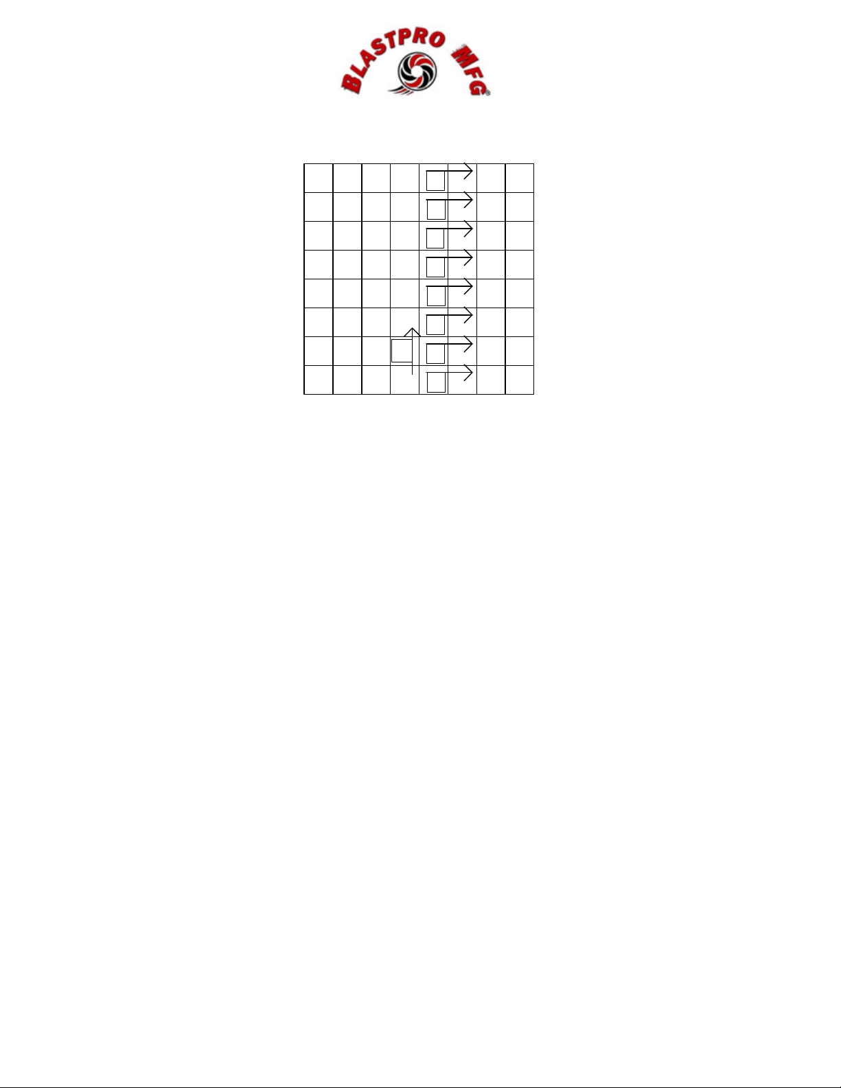
7. Move control levers forward to start removal. It is recommended to make
a single pass in one direction to expose an edge of the material to be
removed. Subsequent passes should be made perpendicular to the initial
pass. See FIGURE 3.1.1.
11
© 2013 Blastpro Manufacturing Inc. ®
Page 12
MACHINE MANUAL BRB-1500
OPERATION
9
8
7
6
5
4
1
3
2
FIGURE 3.1.1
SECTION 3.2: SHUT DOWN
At end of shift or work day:
1. Move machine to level ground for storage.
2. Use the rocker switch in the left control lever to lower the cylinder until the
front caster lifts off of the ground.
3. Flip the brake switch to “ON” position.
4. Depress E-stop.
5. Plug extension cord into machine charging unit.
For long term storage:
1. Move machine to level ground in a secure location for storage.
2. Lift blade to upper-most position.
3. Flip brake switch to “ON” position.
4. Depress E-stop.
5. Remove the blade and/or the blade holder from the front of the machine.
6. Operator should be firmly seated in operator’s seat.
7. Pull E-stop out.
8. Use the rocker switch in the right control lever to lower the cylinders until
the front caster lifts off of the ground.
9. Depress E-stop.
10. Cover the BRB-1500 to protect it from dust and moisture.
CAUTION: Many of the components on the BRB-1500 are not meant to be
exposed to high levels of moisture. It is critical, especially if the machine is
stored in a location exposed to the elements, that it be protected from rain,
splashing or other high levels of water.
12
© 2013 Blastpro Manufacturing Inc. ®
Page 13
MACHINE MANUAL BRB-1500
OPERATION
SECTION 3.3: BLADE SELECTION
Selecting the proper blade for the application will have a dramatic effect on
machine efficiency. If a blade is too wide for the application, there may not be
enough pressure on the blade to stay under the material to be removed. If the
blade is too narrow, the machine may not be removing the maximum material it is
capable of in a single pass.
Based on information about a particular job, start with the widest blade that may
be appropriate for removal. Make a test pass to determine if the blade will stay
under the material. If so, continue with this selected blade. If removal of the
material is relatively easy, consider moving to a larger blade. If it is difficult to
stay under the material, move to a narrower blade.
Always wear leather gloves and use caution when handling blades.
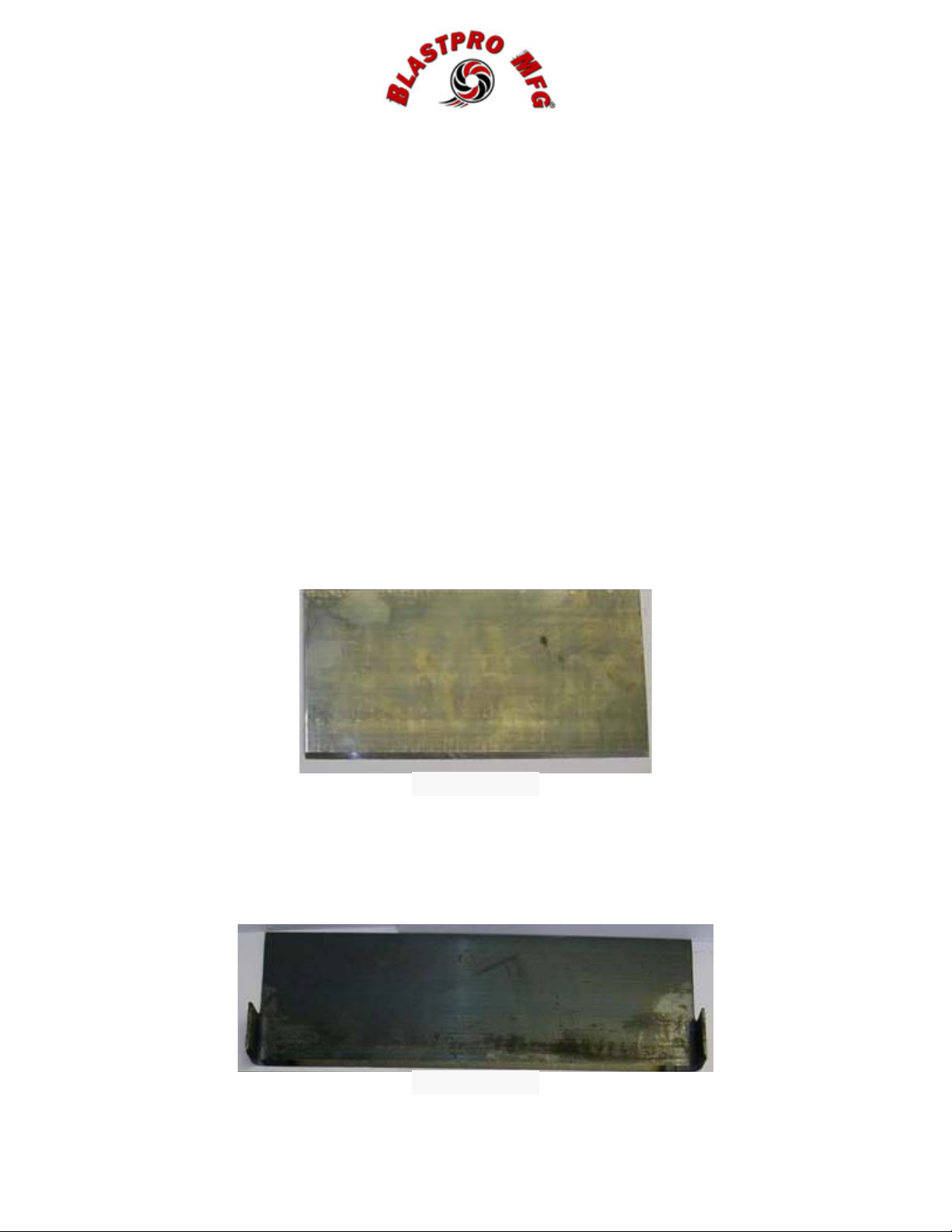
In general, flat blades should be used for scraping glues, mastics, epoxies and
thinsets. SEE FIGURE 3.3.1.
FIGURE 3.3.1
For carpet, rubberized and elastomeric coatings, a carpet blade should be
utilized. The 90° wings on each end of the blade will help keep the removed
material manageable. SEE FIGURE 3.3.2.
FIGURE 3.3.2
13
© 2013 Blastpro Manufacturing Inc. ®
Page 14
MACHINE MANUAL BRB-1500
OPERATION
Blastpro offers a carbide tipped tool for tile removal. This can be inserted into the
3-hole tool adapter on the blade holder. SEE FIGURE 3.3.3
FIGURE 3.3.3
SECTION 3.4: TRANSPORT
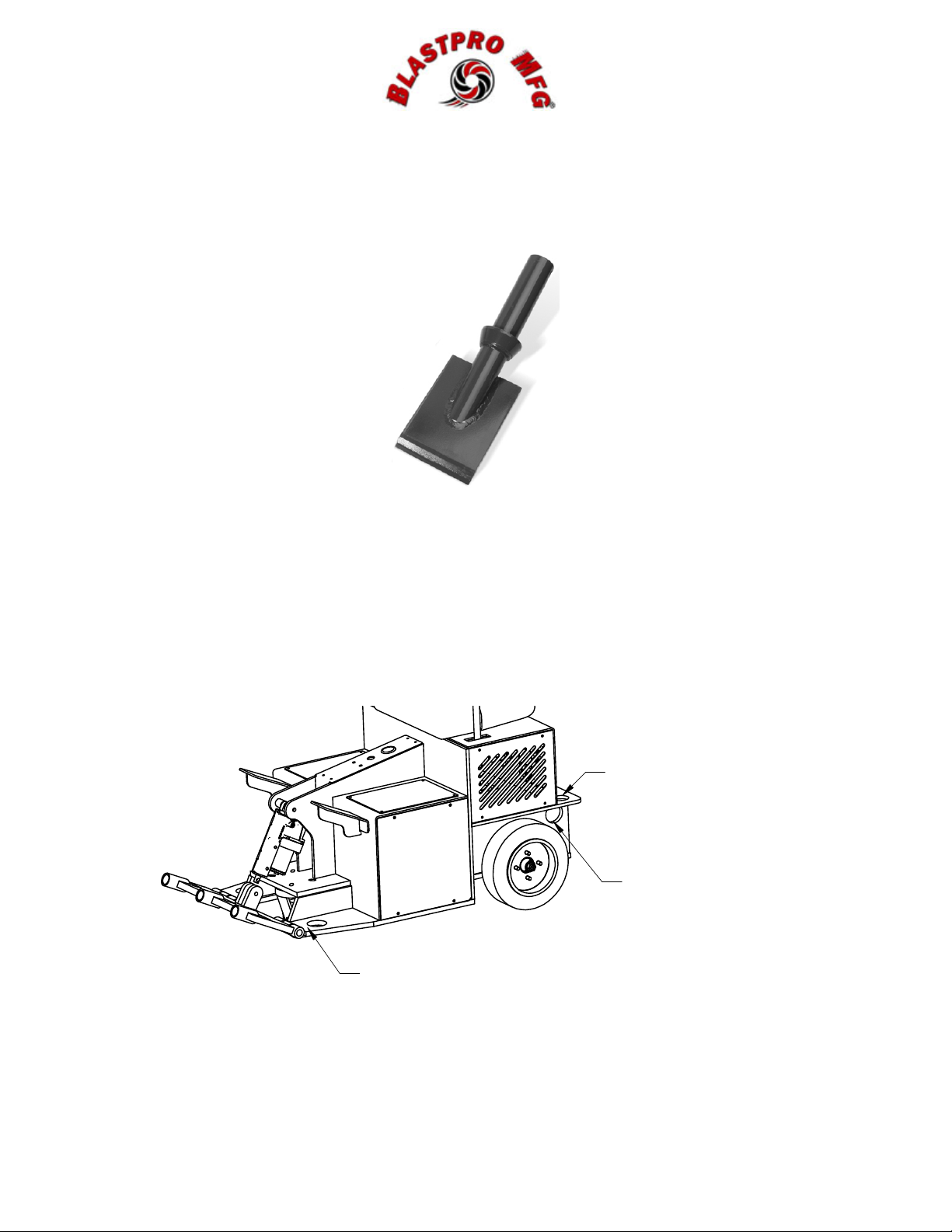
Only use factory installed tie-down/lifting lugs when transporting or moving the
equipment. These are located at the front of the machine, near the blade, and at
the rear of the machine, SEE FIGURE 3.4.1.
TIE DOWN
TYPICAL FAR SIDE
TIE DOWN
TYPICAL FA R SIDE
TIE DOW N
TYPICAL FA R SIDE
FIGURE 3.4.1
14
© 2013 Blastpro Manufacturing Inc. ®
Page 15

MACHINE MANUAL BRB-1500
OPERATION
Never secure the machine with straps or chains across the hydraulic cylinder.
This can result in damage to the cylinder or premature wear.
Verify that lifting straps or chains are rated for the weight of the machine.
Verify that trailer or truck bed is rated for the weight of the machine.
Remove scraper blade and/or pivoting blade holder prior to securing for
transport.
Verify that the blade holder is lowered and that the front swivel caster is off of the
truck or trailer bed.
Never allow personnel to stand under the machine when it is being lifted.
15
© 2013 Blastpro Manufacturing Inc. ®
Page 16

MACHINE MANUAL BRB-1500
MAINTENANCE
SECTION 4.1: MAINTENANCE INTERVALS
SECTION 4.2: TROUBLESHOOTING
SECTION 4.3: MOTOR CONTROLLER FAULT CODES
SECTION 4.4: BATTERY CHARGING
SECTION 4.5: RECOMMENDED SPARE PARTS
SECTION 4.6: RECOMMENDED TOOLS
SECTION 4.7: PARTS LIST AND DRAWINGS
16
© 2013 Blastpro Manufacturing Inc. ®
Page 17

MACHINE MANUAL BRB-1500
MAINTENANCE
SECTION 4.1: MAINTENANCE INTERVALS
Daily, or at the beginning of each shift
If additional assistance is required consult your Blastpro representative,
authorized Blastpro distributor, or qualified electric systems professional.
Always wear leather gloves and use caution when handling blades.
1. Inspect bolted connection for tightness.
2. Inspect wires for damage and abrasion.
3. Inspect blades for excessive wear.
4. Inspect drive wheels for wear.
5. Inspect battery charger outlet for damage and debris.
Every 25 Hours
1. Inspect electrical connections.
2. Grease all blade and cylinder pivot pins.
3. Inspect battery terminals for corrosion.
Every 50 Hours
1. Tighten rear wheel nuts
2. Grease front caster and inspect for wear or damage.
3. Inspect transaxle oil levels
*Perform these maintenance activities more frequently under extremely dusty,
dirty conditions.
17
© 2013 Blastpro Manufacturing Inc. ®
Page 18

MACHINE MANUAL BRB-1500
MAINTENANCE
SECTION 4.2: TROUBLESHOOTING
PROBLEM POSSIBLE CAUSE REMEDY
Electric motor will not
start
Slow coating removal Blade is dull
Battery charger LED
does not come on when
the power is applied to
the battery charger
Battery charger LED
never blinks
No power is present
across the leads from
charger to battery
terminal when
disconnected
Batteries do not receive a
full charge
E-stop is depressed
Fuse is blown
Batteries are dead
Motor controller fault
Blade is too wide
Incorrect blade angle
Not plugged into a live
circuit
Extension cord is
damaged
Leads connecting the
charger to the battery
terminals are damaged or
corroded
Indication of shorted cells
in a battery
The charger will not turn
on until the leads are
connected
Extension cord is too
long or too small
Turn motor switch to
“OFF”, pull out E-stop
button, and try to start
motor.
Replace 10 A fuse
Charge batteries
Remove rear cowling to
retrieve fault code on
controller, and consult
Blastpro Representative
or authorized distributor.
SEE SECTION 4.3
“FAULT CODES”
Flip or replace blade
Replace with narrower
blade
Adjust blade angle up or
down with hydraulic
cylinders
Verify that the circuit you
are plugged into is live
Replace extension cord
Repair/replace/clean the
leads
Replace damaged
battery
Connect leads to battery
terminal with proper
polarity
Use a shorter or bigger
extension cord. Always
use the shortest
possible cord.
18
© 2013 Blastpro Manufacturing Inc. ®
Page 19

MACHINE MANUAL BRB-1500
MAINTENANCE
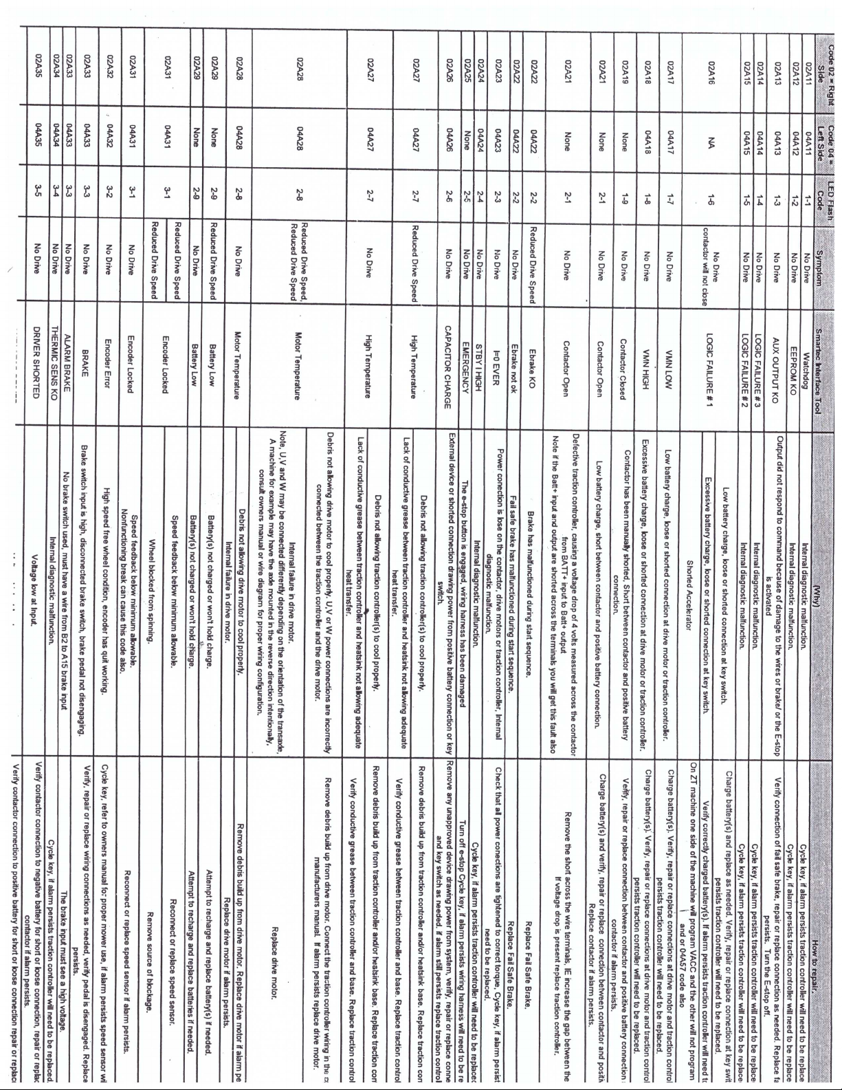
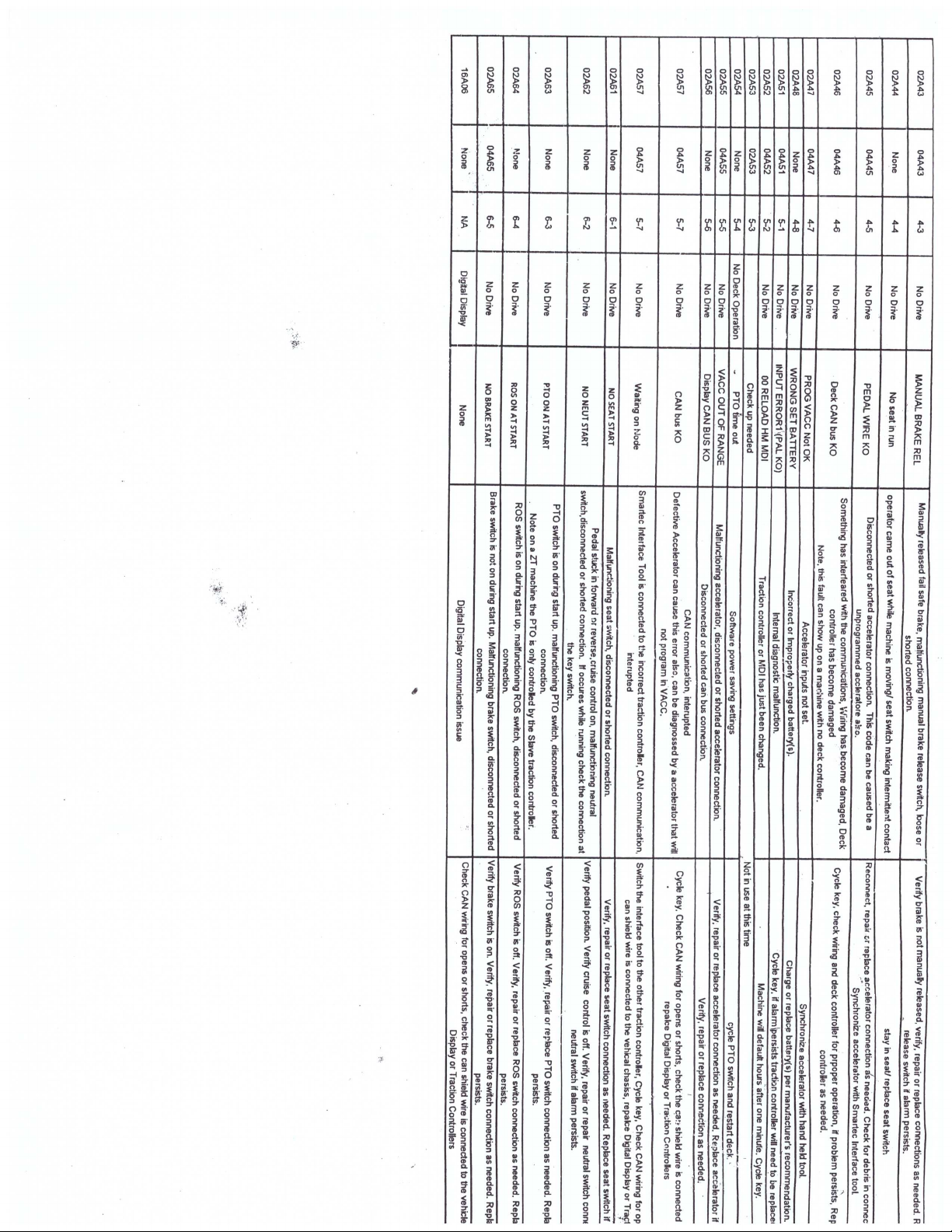
SECTION 4.3: MOTOR CONTROLLER FAULT CODES
LED
FLASH
CODE
6-2 02A62 Control arm
6-5 02A65/04A65 Brake switch
3-3 02A33/04A33
4-8 02A48/0$A48 Machine will not
2-9 02A29 Reduced ground
DIGITAL
DASH
DISPLAY
CODE
SYMPTOM PROBABLE
CAUSE OF
SYMPTOM
Machine will not
move.
move after battery
charge.
drive speed.
not in neutral
position
during
machine start
up.
not engaged
during
machine start
up.
Brake switch
engaged after
machine start
up.
Improperly
charged
battery.
Excessively
low battery.
SYMPTOM
CORRECTION
Place Control
arms in neutral
position and
cycle e-stop
Engage brake
switch and
cycle e-stop.
Disengage the
brake switch.
Charge battery
or replace
defective
battery.
Charge
battery.
19
© 2013 Blastpro Manufacturing Inc. ®
Page 20

MACHINE MANUAL BRB-1500
MAINTENANCE
SECTION 4.4: BATTERY CHARGING
To extend the life of the batteries, the machine should only be used until the
charge meter reads 20%. Fully discharging the batteries on a regular basis will
dramatically decrease the life of the battery, or cause polarity reversal resulting in
complete battery failure. After the battery reaches 10% of charge remaining, the
discharge rate increases dramatically.
Warning: It is normal for the charger to become hot when charging. Do
not obstruct the flow of air around the charger. Do not allow clothing,
blankets or other material to cover the charger. Do not use near fuels,
grain, dust, solvents or other flammables.
The battery charger must be grounded to reduce the risk of electric shock. The
charger is equipped with a ground type plug, and it must be plugged into a
nominal 115 volt, 60 Hz circuit.
Warning: Improper connection of the charger grounding conductor can
result in a risk of an electric shot. DO NOT USE THIS CHARGER ON A TWO
POLE UNGROUNDED OUTLET OR ATTEMPT TO BREAK OFF THE
GROUND PRONG FOR USE ON A RECEPTACLE OR EXTENSION CORD
NOT HAVING A GROUND.
Warning: To reduce the risk of fire, only charge this machine on circuits
provided with a maximum of 20 ampere branch circuit protection (circuit
breaker or fuse, in accordance with the National Electric Code, and all local
codes and ordinances.
1. Plug the female end of the extension cord into the charging outlet on the
rear of the machine.
2. Plug the male end of the extension cord into a properly rated AC outlet.
3. The charger is equipped with an electronic timer. When the battery
reaches the gassing threshold (2.3 V/cell) the timer will activate and run
for three hours. During this period the batteries are in gassing mode.
After three hours the charger will drop the batteries into float mode (2.26
V/cell), indicated by a blinking LED.
4. To discontinue charging, unplug the extension cord from the power outlet
and the machine.
Note: Even after relatively short periods of charging, about 2-3 hours, the battery
indicator may initially read 100% charge. This is an indication of the surface
charge of the battery, and will decrease quickly to the actual percentage of
20
© 2013 Blastpro Manufacturing Inc. ®
Page 21

MACHINE MANUAL BRB-1500
MAINTENANCE
charge while running the machine. This is normal. To achieve a deeper charge
percentage the machine should be left charging for longer periods of time.
Note: Four batteries wired in series some cells become uneven during
charge/discharge cycles. At least once a month, perform two charge cycles
back-to-back. This will bring up cells that are lagging behind fully charged cells.
This is important for overall battery performance.
SECTION 4.5: RECOMMENDED SPARE PARTS
It is recommended that the machine owner/operator keep a minimum of spare
parts with the machine while it is working. Down time due to part failure or lack
of wear parts can far exceed the cost of the parts.
PART NUMBER DESCRIPTION QUANTITY
BTP000451 6” CARPET REMOVAL BLADE Depends on size of job
BTP000553 8” CARPET REMOVAL BLADE Depends on size of job
BTP000554 10” CARPET REMOVAL BLADE Depends on size of job
BTP000555 12” CARPET REMOVAL BLADE Depends on size of job
BTP000853 6” TILE BLADE Depends on size of job
BTP000854 8” TILE BLADE Depends on size of job
BTP000855 12” TILE BLADE W/ BEVEL Depends on size of job
BTP000886 10” TILE BLADE W/ BEVEL Depends on size of job
SECTION 4.6: RECOMMENDED TOOLS
“Recommended Tools” is a list of the minimum tools necessary to maintain
and/or operate the BRB-1500 during normal operation. This list is not meant to
be exhaustive or to indicate the tools required for more intensive maintenance.
Ratchet
Sockets: 7/16”, 1/2”, 9/16” and 3/4”
Combination wrench: 7/16”, 1/2”, 9/16” and 3/4”
Utility knife
Rubber mallet or dead blow hammer
Leather gloves
Multi meter with DC and AC capabilities
21
© 2013 Blastpro Manufacturing Inc. ®
Page 22

MACHINE MANUAL BRB-1500
MAINTENANCE
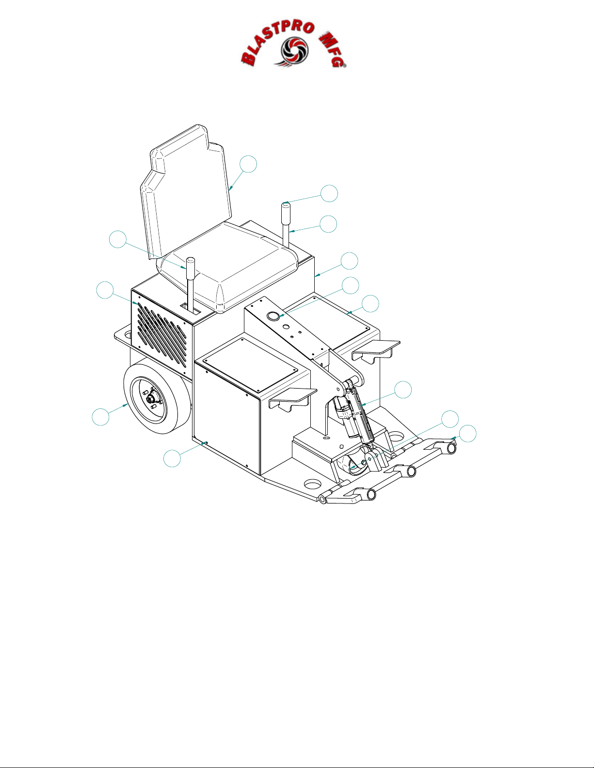
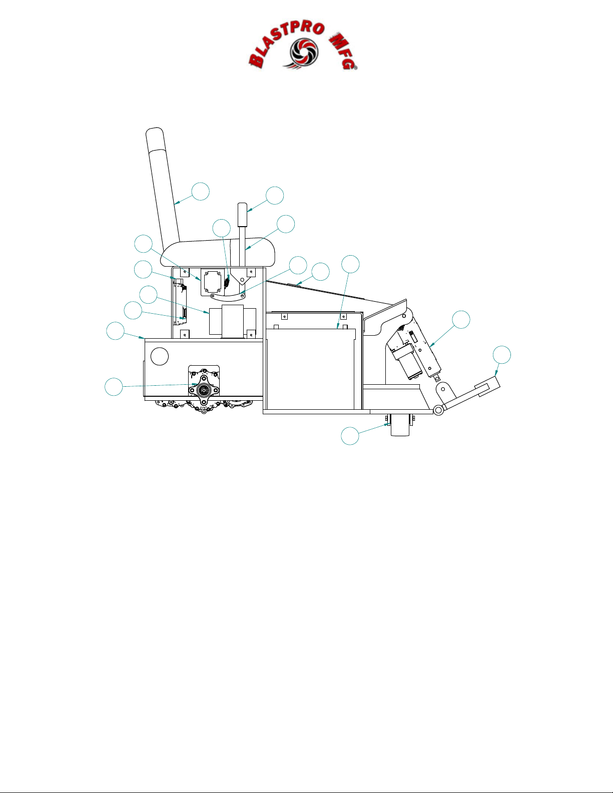
SECTION 4.7: PARTS LIST
ITEM QTY
1 1 BP87000506 CHASSIS WELDMENT
2 1 SCR0020 HIGH BACK SEAT
3 2 BP92000010 INTEGRATED ELECTRIC TRANSAXLE
4 4 BP85000517 BATTERY DRY CELL AGM
5 1 BTP000257 CASTER/SWIVEL
6 2 BP920000 ZT TRACTION CONTROLLER
7 1 BP920000 ZT DOUBLE POLE CONTACTOR
8 2 BP92000022 REAR DRIVE WHEEL
9 1 BP92000012 SCRAPER BLADE WELDMENT
10 2 BP92000015 SIDE CONTROL BOX COVER
11 1 BP92000013 CENTER CONSOLE COVER
12 1 BP92000005 DIGITAL DISPLAY
13 2 BP92000016 TOP BATTERY COVER
14 1 BP87000500 ON BOARD BATTERY CHARGER
15 1 BP92000014 REAR TRANSAXLE COVER
16 2 BP92000017 SIDE BATTERY COVER
17 1 BP92000020 HYDRAULIC CYLINDER
19 2 BP92000023 STEERING SHAFT
20 1 BP9200008 RTN ASSEMBLY
21 2 BP92000026 RTN BRACKET
22 2 BP92000019 HANDLE LINKAGE
23 1 BP9200008 RTN ASSEMBLY
24 1 BP85000012 JOYSTICK 3-POSITION SWITCH
25 1 BP85000011 JOYSTICK STANDARD
26 1 BP92000011 ZT WIRING HARNESS
PART
NUMBER
DESCRIPTION
22
© 2013 Blastpro Manufacturing Inc. ®
Page 23
MACHINE MANUAL BRB-1500
MAINTENANCE
2
25
19
24
1
10
8
16
12
13
17
5
9
23
© 2013 Blastpro Manufacturing Inc. ®
Page 24
MACHINE MANUAL BRB-1500
MAINTENANCE
2
20
21
7
14
6
1
3
24
19
22
12
4
17
9
5
24
© 2013 Blastpro Manufacturing Inc. ®
Page 25
Page 26
 Loading...