

Page 1
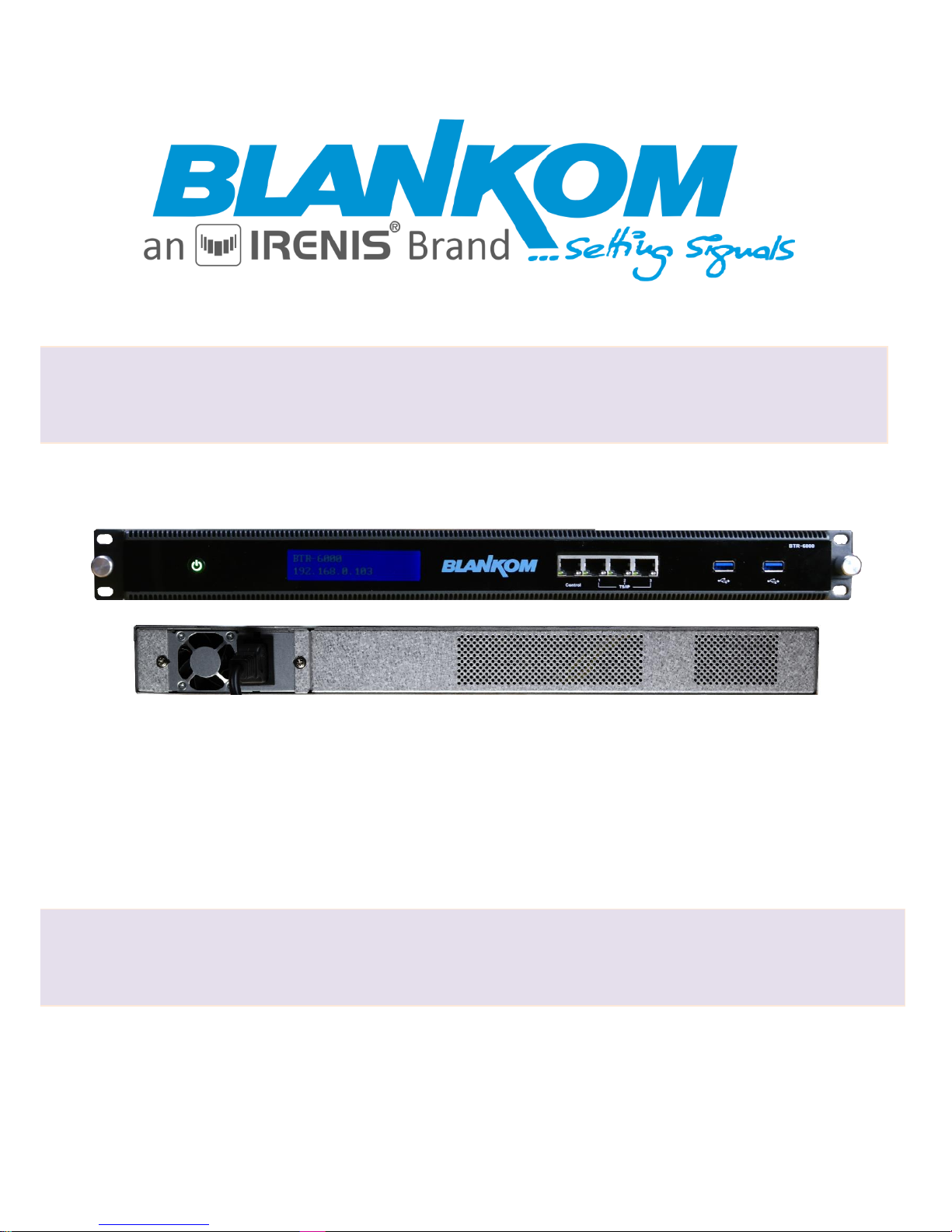
Transcoder BTR-6000
User Manual
Page 2

BLANKOM BTR-6000 Transcoder User Manual
Version 1.0 – 06-2018 Page - 2 -
Table of Content
Product Outline ..................................................................................................................... 3
Technical Data: ...................................................................................................................... 3
Statement: ............................................................................................................................. 4
Application Example .............................................................................................................. 5
Connecting ............................................................................................................................. 6
First login and System Menu: ................................................................................................ 6
Network Settings: .................................................................................................................. 7
Server-Settings: ..................................................................................................................... 8
IP Input configuration: ........................................................................................................... 8
Transcoding: ........................................................................................................................ 13
IP Remux- Menu: ................................................................................................................. 16
IP Backup function: .............................................................................................................. 20
Example for streaming to VIMEO Live by RTMP by our tiny boxed encoders: ................... 23
General notes about Streams: ............................................................................................ 24
Multicast streams: ............................................................................................................... 24
Registered port .................................................................................................................... 26
Range for Ephemeral port ................................................................................................... 26
Packet structure .................................................................................................................. 27
RTP: ...................................................................................................................................... 27
Contact: ............................................................................................................................... 29
Page 3

BLANKOM BTR-6000 Transcoder User Manual
Version 1.0 – 06-2018 Page - 3 -
Product Outline
The Transcoder BTR-6000, processes SD/HD efficiently based on the high-performance CPU/GPU designed
specifically for IPTV systems with h.264 AVC and additional HEVC/h.265 low bit rate compression. The TV
Services can be converted to a low bit rate (< 600kbps) while maintaining the image quality. It supports IP
re-multiplexing to MPTS and streaming SPTS. The multiple resolution functions can be used perfectly for
multi- screen serving TVs, Smart phones, tablets, PCs, … . The user friendly network management Web-IF
helps to setup and monitor the working status.
Key Features:
Video compliant with H.265/HEVC Baseline, [email protected] or less
H.264 AVC Baseline, Main&High [email protected] or less
Audio compliant with MPEG-1 Layer II Audio, AAC transcoding, Multi-audio transcoding and pass
through
Resolution from 96*96 to 4096*2160
Bitrate from 200Kbps to 20Mbps
h.265 HEVC capacity: 4K x1/ 1080P x8 / 720P x16 / SD x32 services per chassis
h.264 AVC capacity: HD x16 / SD x32 services per chassis
Support local video transcoding and delivery
Rolling subtitle & Logo insertion
PCR self-correction
PSI/SI edition and PID pass through
Up to 200 MPTS/SPTS output, 100Mbps max for each
1+N output backup system
Web-Interface
Technical Data:
Input
Input Interface
1000M/100M/10M RJ45 x 4pcs Full Duplex
TS/IP Input Bit Rate
800Mbps - RJ45
Data Protocol
UDP, ICMP, IGMP V1, V2, V3, RTP, HTTP, RTSP, FTP, RTMP, HLS (HTTP Live
Streaming)
Transcoder source
IP inputs, Local files (USB 3.0)
IP Protocol
Unicast, Multicast
Video/Audio Format
Video
H.265/HEVC, H.264/AVC, MPEG-2, MPEG-4
Audio
MPEG-1, MPEG-2, MPEG-4, AAC
Re-Multiplex
Input
SPTS / MPTS
Null package
processing
Zero packet PID 8191dec pass through, insertion and filtering
TS Editing
Service editing
PSI/SI editing
PID pass through / remapping
Page 4

BLANKOM BTR-6000 Transcoder User Manual
Version 1.0 – 06-2018 Page - 4 -
Statement:
Text and pictures herein are subject to changes w/o notifications.
The user manual will be updated in real time without special notice.
This user manual is provided only as a reference guide for technicians as examples.
Default Login: Visitor (readonly), admin/admin or root/12345
PCR auto-correction
Maximum bitrate
100Mbps each
Maximum TS count
200 input TS Streams + 200 output TS Streams (with transcoder function disable)
IP Output
Interface
1000M/100M/10M RJ45 x 4pcs Full Duplex
TS/IP Output
Average per port 800Mbps
Protocols
UDP, RTMP, HLS, FTP, RTP (for MUX only)
IP addressing
Unicast, Multicast
Type
IP Streaming or File
Video/Audio Format for Encoding
Video Format
HEVC(h.265)/h.264
Audio Format
MPEG-1 Layer 2, MPEG-2 AAC, MPEG-4 AAC
Package Format
MPEG-TS
Bitrate Control
VBR,CBR
Video resolution
4096*2160, 3840*2160, 2560*1440,1920*1080, 1280*720, 720*576, 720*480,
704*576, 704*288, 640*480, 544*576, 544*480, 480*576, 480*320, 480*270,
360*320, 352*576, 352*288, 320*240, 320*200, 240*160, 192*192, 192*128,
176*144, 128*96, 96*96 …
Video aspect ratio
Auto, 4:3, 16:9
Video frame rate
Auto, 30fps, 29.97fps, 25fps, 24fps, 23.97fps
Video bitrate
200Kbps … 20Mbps
Audio sampling rate
32 KHz, 44.1 KHz, 48 KHz
Audio bit rate
32kbps, 64kbps, 96kbps, 128kbps, 192kbps, 256kbps, 384kbps
Control & Monitoring
Interface
RJ45 x1pcs, 1000M/100M
Protocol
HTTP Web GUI
General
Power Consumption
AC 110V…240V, 6A, 47…63Hz, max. 350W
Operation
temperature
5…45 ºC
Storage temperature
-10…65 ºC
Dimension
430mm x 335mm x 44mm
Gross Weight
8.7Kg
Page 5
BLANKOM BTR-6000 Transcoder User Manual
Version 1.0 – 06-2018 Page - 5 -
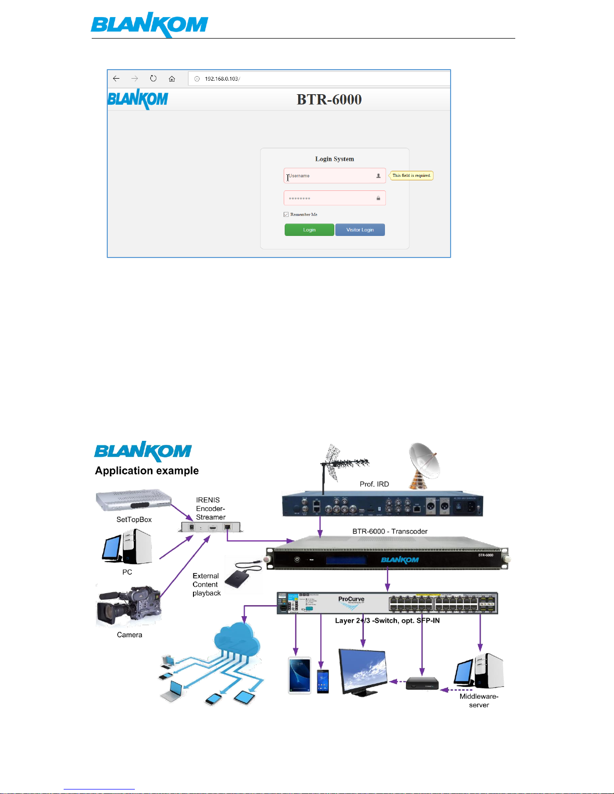
Default is: root/12345 or admin/admin
Set the administrator’s computer IP as: 192.168.0.* to avoid IP conflicting with the units own IP
address 192.168.0.103. - Or always shown is the actual IP address of the network management
address ‘Control’ port at the front panel (left) after booting.
192.168.0.*: use an IP setting “*” in the number range 2-254 and except the units default IP.
Remark: .0 is often the network router, .1 often the Gateway of the used router, .255 might be a
network broadcasting address.
Please change these account settings according to your local policy and network. -> Do not forget
to safe and backup the configuration by Web-Interface and its related system-sub-menu.
The encoder can be always set back to factory default settings by using the RESET-swith in Web-IF.
Application Example
Page 6
BLANKOM BTR-6000 Transcoder User Manual
Version 1.0 – 06-2018 Page - 6 -
Connecting
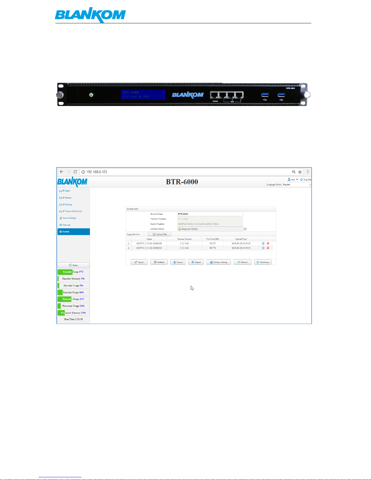
The Transcoder comes with 1x Management RJ45 Interface for Web-access and 3 GbE Ports for the
streaming connection:
The USB ports are equipped for future use.
The rear has only one IEC connector for main voltage 110….230VAC.
First login and System Menu:
After entering username and password (root/12345) you should first enter the System menu:
In the System menu you are getting actual status information about the Transcoder and can safe or
import former stored settings, switch back to factory defaults, reboot and Shutdown. Please do not
disconnect power before using the shutdown button here and wait until it will be ready.
Remark: The language selection Menu in the top right corner depends on regions and might be not
shown while the default language is always english.
Initial we should take care about the Network ports now. Please keep always in mind, to avoid IP
address conflicts with your existing network topology.
Page 7
BLANKOM BTR-6000 Transcoder User Manual
Version 1.0 – 06-2018 Page - 7 -
Network Settings:
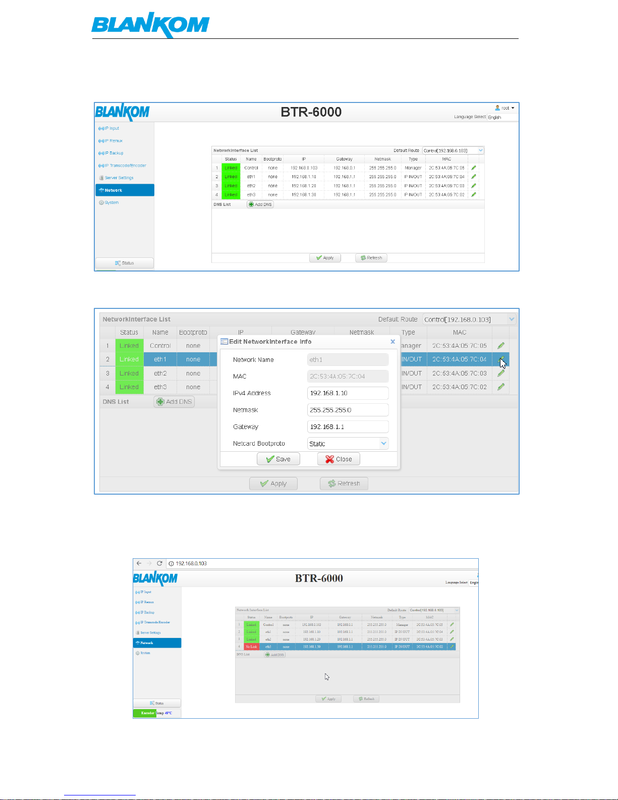
Up to 3 x GbE can be connected and selected for IP Inputs and outputs (bi-directional).
Changes can be done by editing the ports:
If DNS addresses are needed, you can add them as well.
Hint: Popup blocker should be disabled in your browser settings.
If you accidently try to move this popup window, you might end up in a not reachable status of this
setup. Please restart a new login again:
Page 8
BLANKOM BTR-6000 Transcoder User Manual
Version 1.0 – 06-2018 Page - 8 -
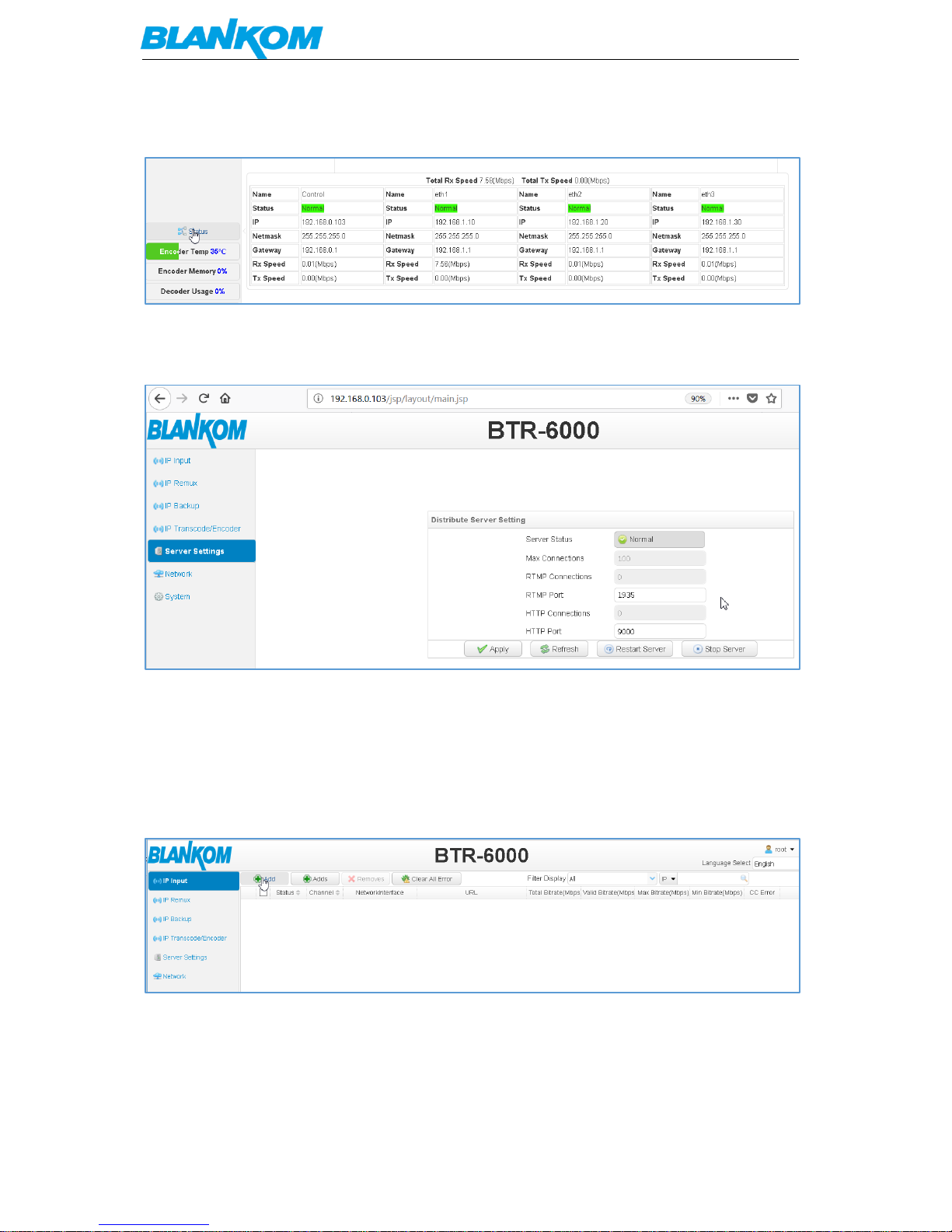
Selecting Status will popup actual information:
Server-Settings:
In this menu, you can change the http and RTMP ports for streaming to i.e. VIMEO, WOWZA or
catching Http streaming.
IP Input configuration:
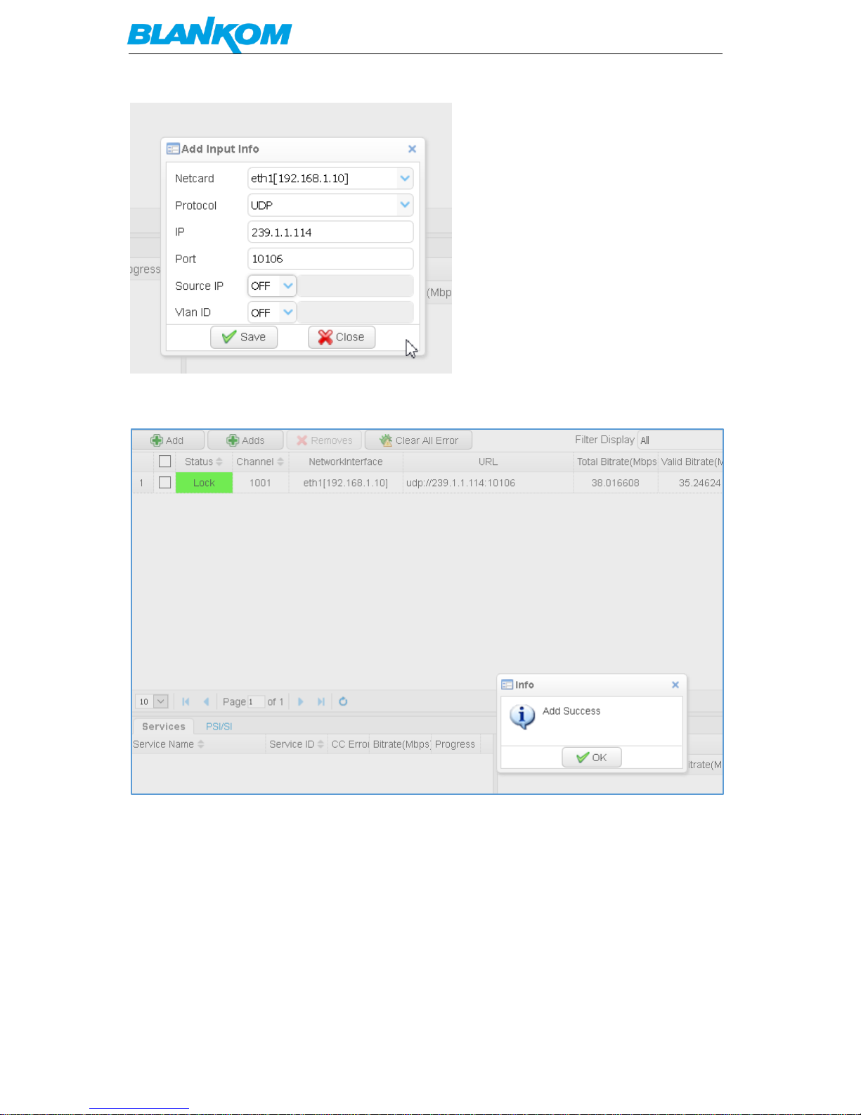
Now we start to get some streams in:
Press add- button or insert multiple with the Adds-button:
Page 9
BLANKOM BTR-6000 Transcoder User Manual
Version 1.0 – 06-2018 Page - 9 -
This is an MPTS. Source IP as well as VLAN
ID can be chosen if applicable. Source IP might be to serve the SSM – feature of your streamer
(SSM=Source Specific Multicast).
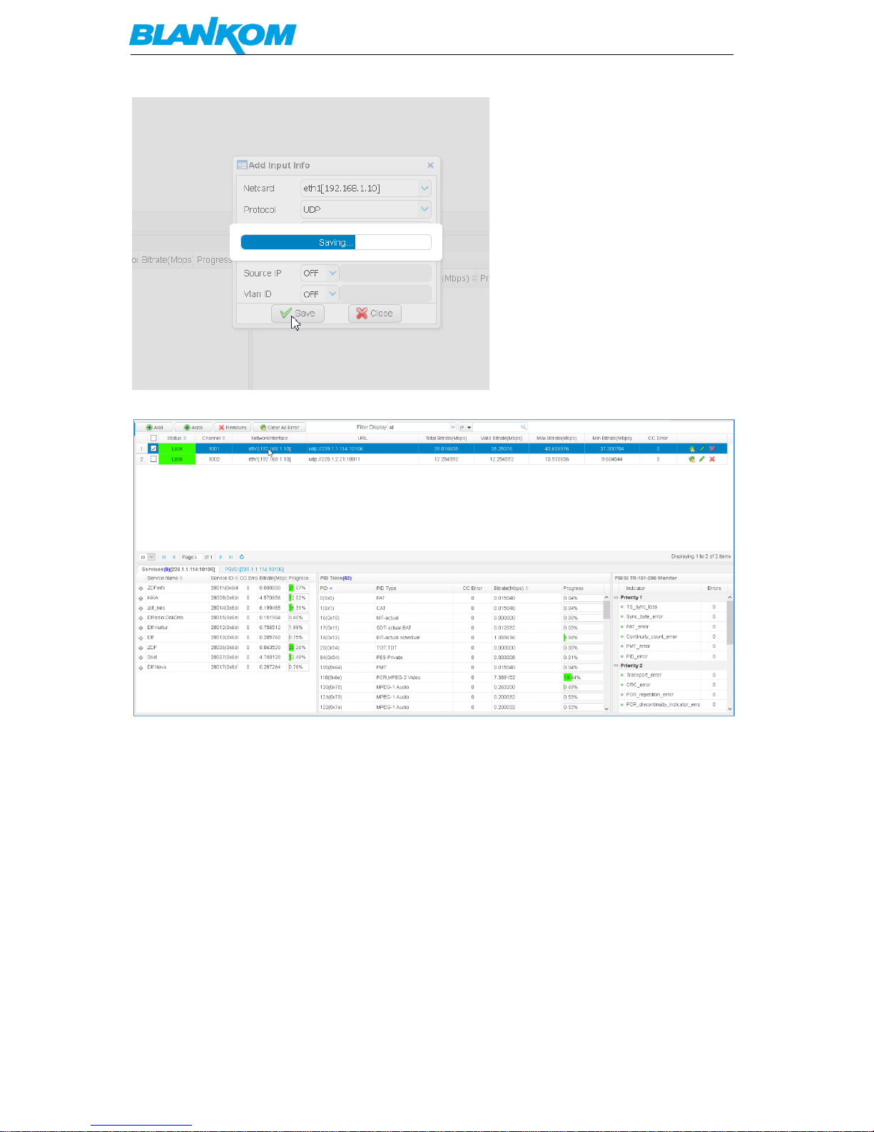
We add some more SPTS now:
Page 10
BLANKOM BTR-6000 Transcoder User Manual
Version 1.0 – 06-2018 Page - 10 -
Selecting the stream will give you information about the content:
Expanding the view by using the ‘+’:
Page 11
BLANKOM BTR-6000 Transcoder User Manual
Version 1.0 – 06-2018 Page - 11 -
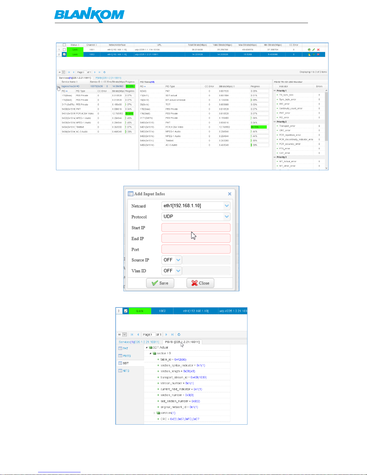
If multiple addresses want to be configured use ADDS:
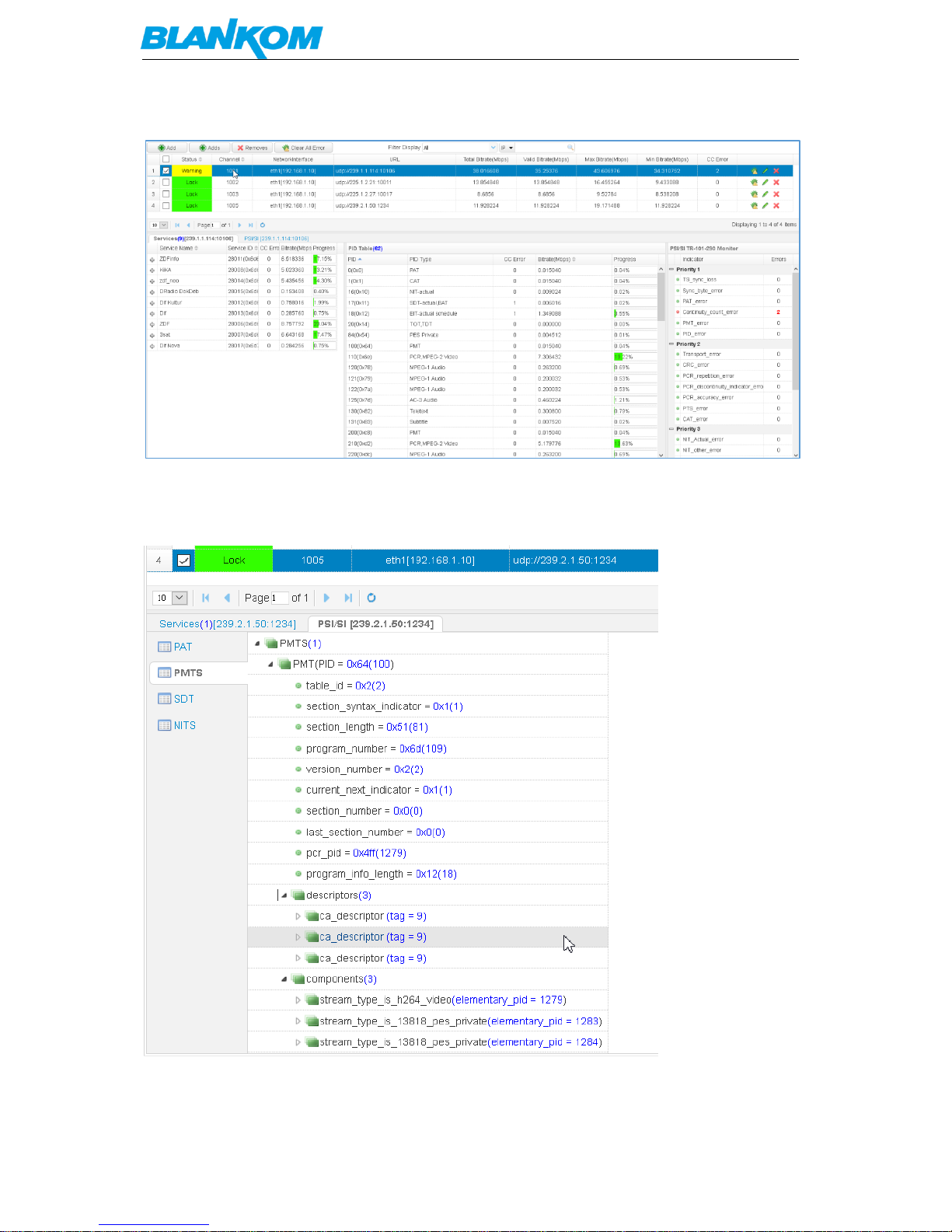
Get more detailed information of the IP Input stream and even details from the PSI/SI:
Page 12
BLANKOM BTR-6000 Transcoder User Manual
Version 1.0 – 06-2018 Page - 12 -
You’ll get a ‘warning’ if some stream errors occur:
CC errors might come up if the receiver streamer input signal got some input weakness like here
the DVB-S streamer…. Blankom DRD700 SAT-> IP
Streams containing encryption Information will be shown as well:
You can PID filter in a later step…
Page 13

BLANKOM BTR-6000 Transcoder User Manual
Version 1.0 – 06-2018 Page - 13 -
Now that we have some streams coming in we like to transcode them:
Transcoding:
The HDMI/SDI encoding Menu is only for BTR units equipped with either an HDMI Input card or an
SDI Input card (optional). Files adding will be also a future release upgrade.
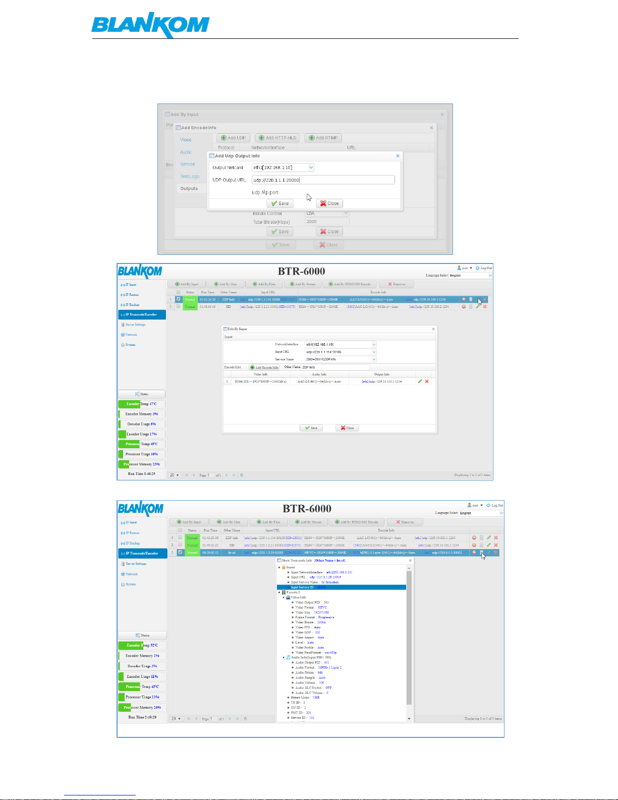
Different Input methods can be chosen –
Page 14
BLANKOM BTR-6000 Transcoder User Manual
Version 1.0 – 06-2018 Page - 14 -
Set the values according to your needs. Audio, Text Logo Service Informations … and finally the
output stream GbE port (eth1…3) destination and address:
Detailed Information about your transcoded Service can be gathered by selecting the leaf-button:
Page 15
BLANKOM BTR-6000 Transcoder User Manual
Version 1.0 – 06-2018 Page - 15 -
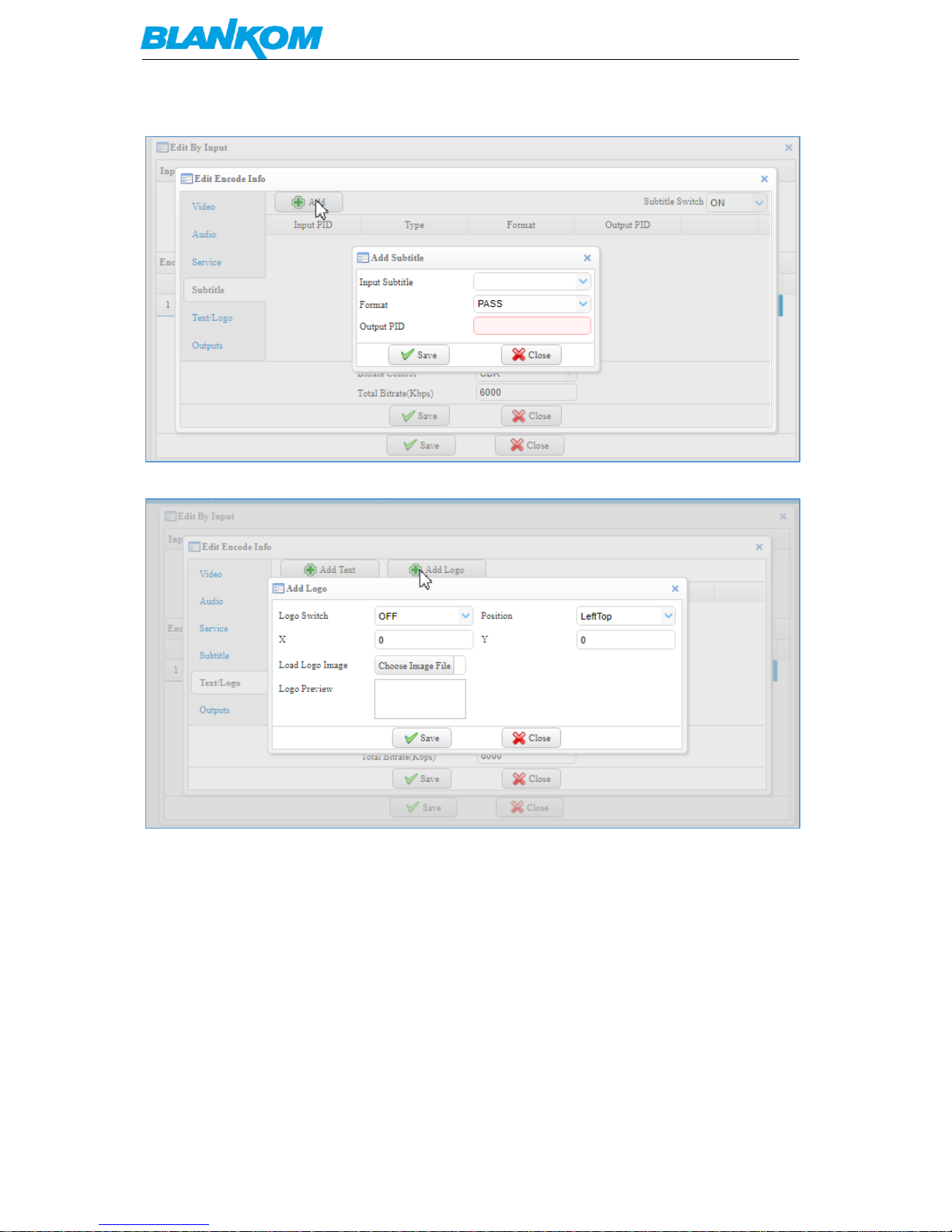
Subtitles can be passed or injected:
LOGO’s ad advertisements or simple Text strings can be added to the transcoded Service as well:
After setting up some encodings, later on they can be changed as well.
ADD by MUX would need an already former configured Remultiplexing Stream by the
Page 16
BLANKOM BTR-6000 Transcoder User Manual
Version 1.0 – 06-2018 Page - 16 -
IP Remux- Menu:
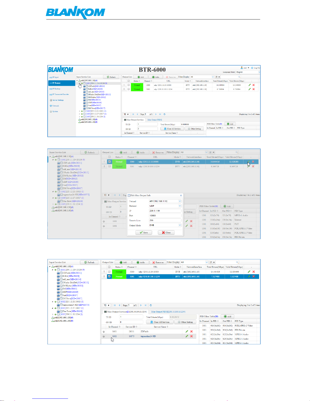
Entering this menu, allows the user to use already incoming streams to be remultiplexed to new
MPTS:
First off all, you need to setup one or more output streams:
Chose DVB-Mode or IPTV. Than save and you can drag and drop services from the left side (Input
streams) to the new mux:
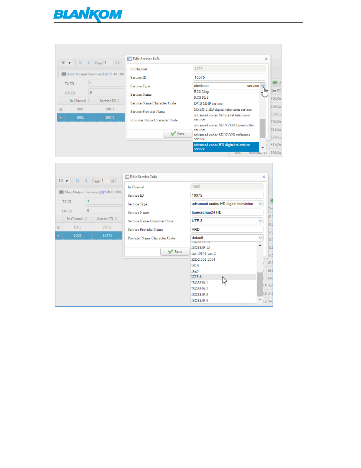
To edit the content just use the PEN:
Page 17
BLANKOM BTR-6000 Transcoder User Manual
Version 1.0 – 06-2018 Page - 17 -
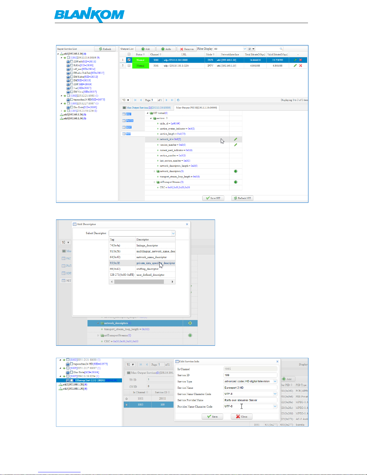
In the PSI/SI submenu you can edit and add i.e. PSI or other NIT table values:
Page 18
BLANKOM BTR-6000 Transcoder User Manual
Version 1.0 – 06-2018 Page - 18 -
As well as inserting descriptors:
and manage i.e. character table corrections:
Page 19
BLANKOM BTR-6000 Transcoder User Manual
Version 1.0 – 06-2018 Page - 19 -
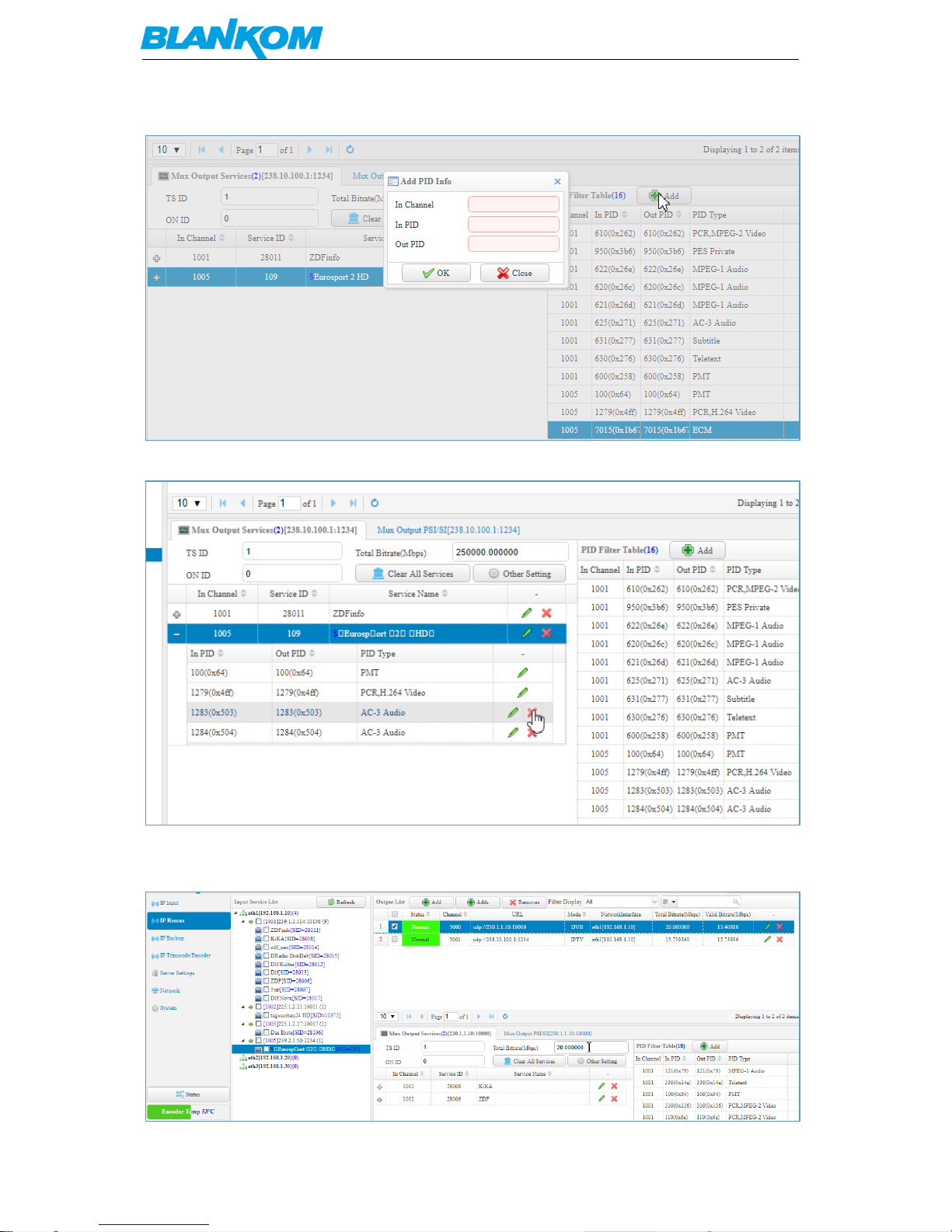
As well as do PID-Remapping:
Or even PID filtering (dropping):
To add zero-packets (PID8191dec) to the output stream, you need to configure DVB-Mode and than
enter a max. Total bitrate in the Mux output Services like:
Page 20
BLANKOM BTR-6000 Transcoder User Manual
Version 1.0 – 06-2018 Page - 20 -
IP Backup function:
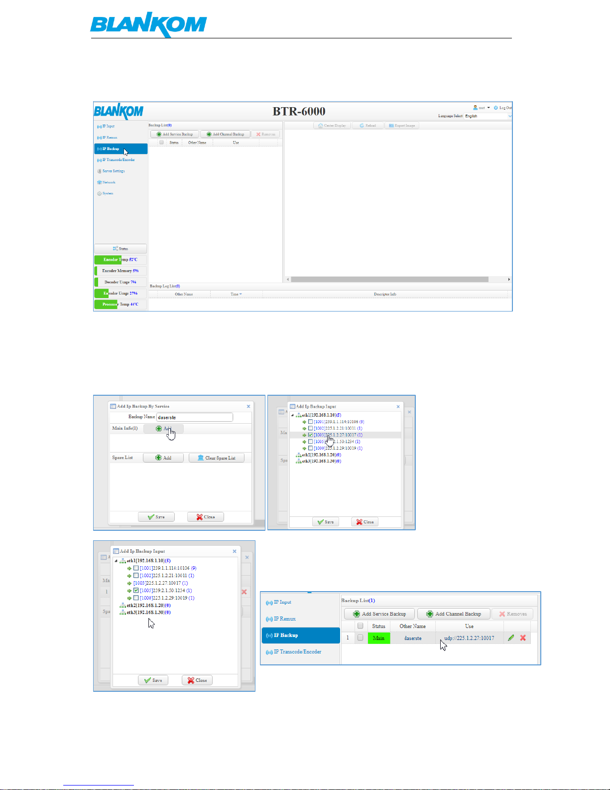
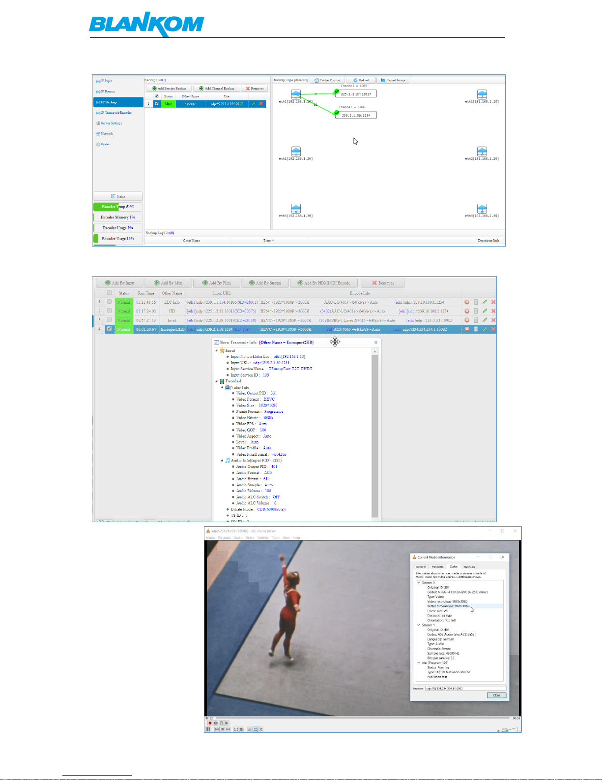
Add a stream first or here we are using existing ones just to show how it works…
The Reason of this function is obvious?: If a mayor stream input will fail, the backup address will be
used to process it so the output encoding has still content. Usually as an example: If the HD channel
you are transcoding will be interrupted somehow, you create the backup channel from i.e. an SD
source stream.
A nice feature is the Topology-Overview:
Page 21
BLANKOM BTR-6000 Transcoder User Manual
Version 1.0 – 06-2018 Page - 21 -
Example for setup another transcoding h.264 to HEVC:
Can be checked by VLC:
Page 22
BLANKOM BTR-6000 Transcoder User Manual
Version 1.0 – 06-2018 Page - 22 -
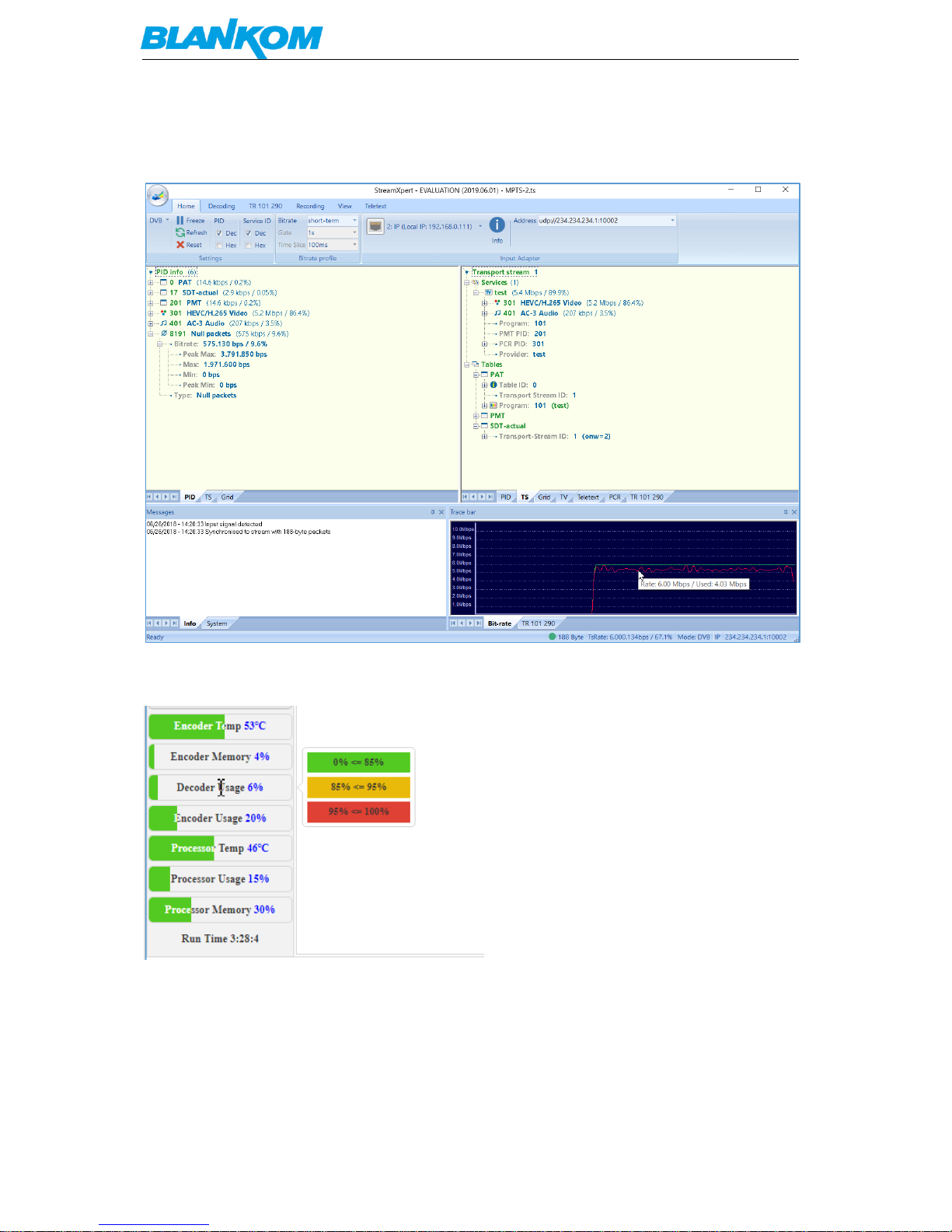
Or by DekTec:
Because we have setup CBR instead of VBR, Null-packets are added on PID8191dec to the encoded
IP output:
When editing streams to transcode, please always have an eye on:
It will change colour if the encoder processes
are coming to its limits. The max. mix of transcoded and processed services depending on your
quality settings.
BTW: We assume, that the user is familiar with the Codecs (Audio/Video) and their settings (GOP
etc…) , DVB and IPTV Rules/Tables and of course Network mechanism like IGMP, RTP, etc…
Page 23
BLANKOM BTR-6000 Transcoder User Manual
Version 1.0 – 06-2018 Page - 23 -
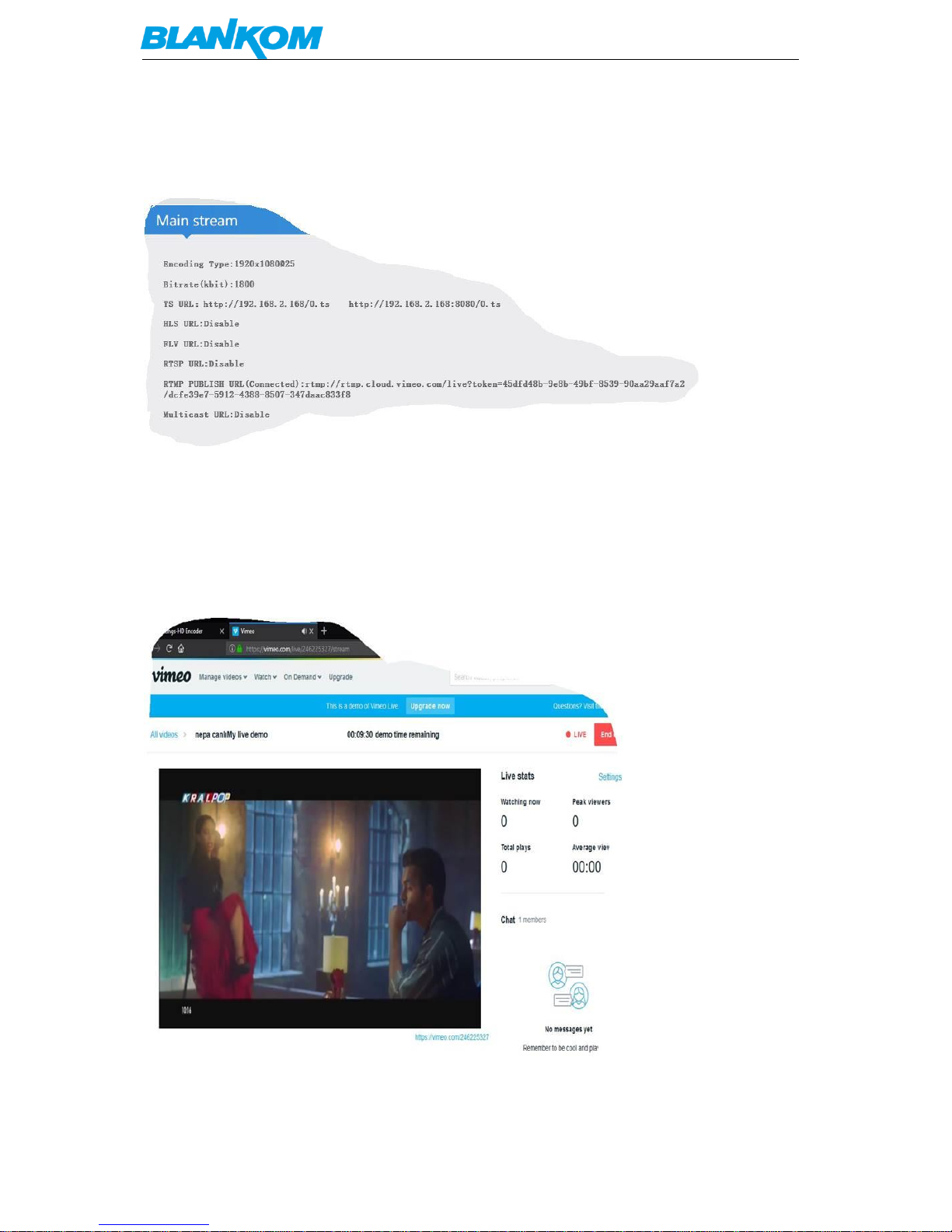
Example for streaming to VIMEO Live by RTMP by our tiny boxed
encoders:
VIMEO gives the user an RTMP –address with a live token at the end. No username/password is
necessary because they handover individual stream-keys which simply needs to be inserted as
rtmp://rtmp.cloud.vimeo.com/live?token=*************/streamkey
Than you can control it by checking the vimeo live portal of your stream:
Page 24
BLANKOM BTR-6000 Transcoder User Manual
Version 1.0 – 06-2018 Page - 24 -
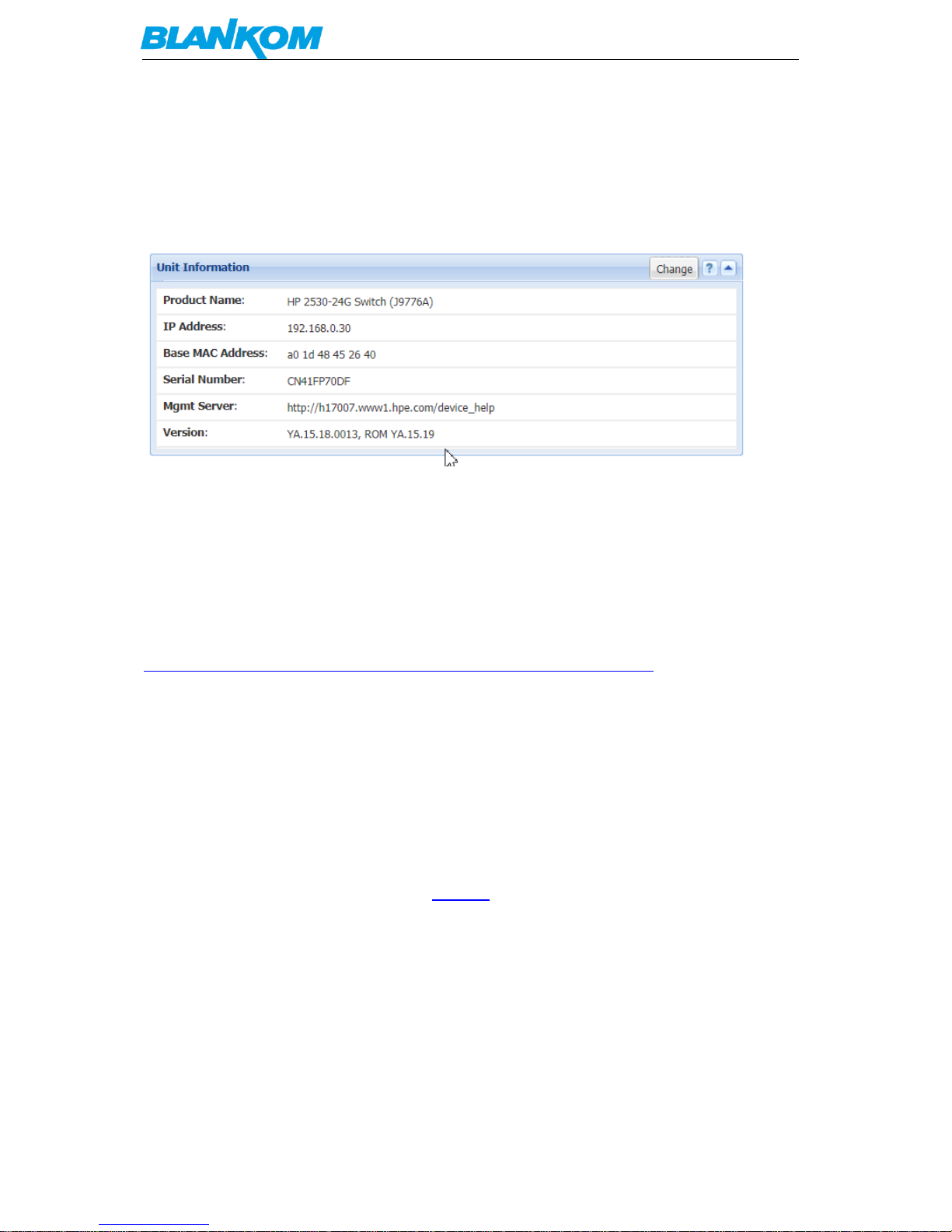
As a Multicast capable Switch we recommend is the HP (ARUVA) 2530 24G or 48G.
(For Floor switches we have an own branded one and support IGMP as well) IGMP should be set to
ON in the port configs. The latest HP Firmware might not be the best choice. Better to test IGMP
functions before installation into a HOT running System and eventually do a downgrade of the
Firmware. This one works:
General notes about Streams:
Multicast streams:
Multicast Address Ranges:
We recommend, that the addressing of your Multicast streams should be in conjunction with this listings to
avoid conflicts with other network equipment or protocols.
https://www.iana.org/assignments/multicast-addresses/multicast-addresses.xhtml
One small part from this:
IPv4 Multicast Address Space Registry
Last Updated
2018-01-05
Expert(s)
Stig Venaas
Note
Host Extensions for IP Multicasting [RFC1112] specifies the extensions required of a host
implementation of the Internet Protocol (IP) to support multicasting. The multicast
addresses are in the range 224.0.0.0 through 239.255.255.255. Address assignments are
listed below.
The range of addresses between 224.0.0.0 and 224.0.0.255, inclusive, is reserved for the
use of routing protocols and other low-level topology discovery or maintenance protocols,
such as gateway discovery and group membership reporting. Multicast routers should
not forward any multicast datagram with destination addresses in this range, regardless of
its TTL.
Page 25

BLANKOM BTR-6000 Transcoder User Manual
Version 1.0 – 06-2018 Page - 25 -
Available Formats XML HTML Plain text
Registries included below
Local Network Control Block (224.0.0.0 - 224.0.0.255 (224.0.0/24))
Internetwork Control Block (224.0.1.0 - 224.0.1.255 (224.0.1/24))
AD-HOC Block I (224.0.2.0 - 224.0.255.255)
RESERVED (224.1.0.0-224.1.255.255 (224.1/16))
SDP/SAP Block (224.2.0.0-224.2.255.255 (224.2/16))
AD-HOC Block II (224.3.0.0-224.4.255.255 (224.3/16, 224.4/16))
RESERVED (224.5.0.0-224.251.255.255 (251 /16s))
DIS Transient Groups 224.252.0.0-224.255.255.255 (224.252/14))
RESERVED (225.0.0.0-231.255.255.255 (7 /8s))
Source-Specific Multicast Block (232.0.0.0-232.255.255.255 (232/8))
GLOP Block
AD-HOC Block III (233.252.0.0-233.255.255.255 (233.252/14))
Unicast-Prefix-based IPv4 Multicast Addresses
Scoped Multicast Ranges
Relative Addresses used with Scoped Multicast Addresses
Multicast (as opposed to unicast) is used to send UDP packets from 1 source to multiple
destination servers. This is useful for example for streaming from a satellite/DVB-T receiver
to multiple receiving PCs for playback. Multicast can also be used on the output of an
encoder to feed multiple streaming servers. Multicast only works with UDP and is not
possible with TCP due to the 2 way nature of TCP, most commonly multicast is used with
RTP and MPEG2-TS.
A multicast IP address must be chosen according to IANA information, we recommend
using an address in the range 239.0.0.0 to 239.255.255.255 as this is reserved for private
use. Using multicast addresses in the 224.0.0.0 range may clash with existing services and
cause your stream to fail. For more details see
http://www.iana.org/assignments/multicast-addresses/multicast-addresses.xml
Choosing a UDP port number for multicast streams is also important. Even if you use a
different multicast IP for each of your streams, we strongly recommend using different
UDP port numbers as well. This is because a server and all software running on the server
receives ALL multicast traffic on an open port and extra processing is required to filter out
the required traffic. If the each stream arrives on a different port, the server can safely
ignore any traffic on ports that are not open. Port numbers MUST be chosen so that don't
clash with any existing services or ephemeral ranges. The ephemeral range for Windows
Vista, 7, 2008 is 49152 to 65535, for older Windows it is 1025 to 5000 and for Linux it is
32768 to 61000. For more information on Windows see
http://support.microsoft.com/kb/929851 Care should also be taken to avoid system ports
0 to 1024. See http://www.iana.org/assignments/service-names-port-numbers/service-
Page 26

BLANKOM BTR-6000 Transcoder User Manual
Version 1.0 – 06-2018 Page - 26 -
names-port-numbers.xml Generally one of the unassigned User Ports (1024-49151) should
be used, you can run the netstat -abn (as admin under windows) command to see which
ports are currently in use.
Registered port
A registered port is a network port (a sub-address defined within the Internet Protocol, in
the range 1024–49151) assigned by the Internet Assigned Numbers Authority (IANA) (or by
Internet Corporation for Assigned Names and Numbers (ICANN) before March 21, 2001,
[1]
or by USC/ISI before 1998) for use with a certain protocol or application.
Ports with numbers 0–1023 are called system or well-known ports; ports with numbers
1024-49151 are called user or registered ports, and ports with numbers 49152-65535 are
called dynamic and/or private ports.
[2]
Both system and user ports are used by transport
protocols (TCP, UDP, DCCP, SCTP) to indicate an application or service.
Ports 0–1023 – system or well-known ports
Ports 1024–49151 – user or registered ports
Ports >49151 – dynamic / private ports
https://en.wikipedia.org/wiki/List_of_TCP_and_UDP_port_numbers
Range for Ephemeral port
The Internet Assigned Numbers Authority (IANA) suggests the range 49152 to 65535 (215+214 to
216−1) for dynamic or private ports.
[1]
Many Linux kernels use the port range 32768 to 61000.
[note 2]
FreeBSD has used the IANA port range
since release 4.6. Previous versions, including the Berkeley Software Distribution (BSD), use ports
1024 to 5000 as ephemeral ports.
[2][3]
Microsoft Windows operating systems through XP use the range 1025–5000 as ephemeral ports by
default.
[4]
Windows Vista, Windows 7, and Server 2008 use the IANA range by default.
[5]
Windows
Server 2003 uses the range 1025–5000 by default, until Microsoft security update MS08-037 from
2008 is installed, after which it uses the IANA range by default.
[6]
Windows Server 2008 with
Exchange Server 2007 installed has a default port range of 1025–60000.
[7]
In addition to the default
range, all versions of Windows since Windows 2000 have the option of specifying a custom range
anywhere within 1025–65535.
[8][9]
Page 27

BLANKOM BTR-6000 Transcoder User Manual
Version 1.0 – 06-2018 Page - 27 -
Packet structure
UDP Header
Offsets
Octet
0 1 2
3
Octet
Bit
0
1
2
3
4
5
6
7
8
9
10
11
12
13
14
15
16
17
18
19
20
21
22
23
24
25
26
27
28
29
30
31 0 0
Source port
Destination port
4
32
Length
Checksum
The UDP header consists of 4 fields, each of which is 2 bytes (16 bits).
[1]
The use of the fields "Checksum" and
"Source port" is optional in IPv4 (pink background in table). In IPv6 only the source port is optional (see
below).
Source port number
This field identifies the sender's port when meaningful and should be assumed to be the port to
reply to if needed. If not used, then it should be zero. If the source host is the client, the port
number is likely to be an ephemeral port number. If the source host is the server, the port number is
likely to be a well-known port number.
[4]
Destination port number
This field identifies the receiver's port and is required. Similar to source port number, if the client is
the destination host then the port number will likely be an ephemeral port number and if the
destination host is the server then the port number will likely be a well-known port number.
[4]
Length
A field that specifies the length in bytes of the UDP header and UDP data. The minimum length is 8
bytes because that is the length of the header. The field size sets a theoretical limit of 65,535 bytes
(8 byte header + 65,527 bytes of data) for a UDP datagram. However the actual limit for the data
length, which is imposed by the underlying IPv4 protocol, is 65,507 bytes (65,535 − 8 byte UDP
header − 20 byte IP header).
[4]
In IPv6 jumbograms it is possible to have UDP packets of size greater than 65,535 bytes.
[5]
RFC 2675
specifies that the length field is set to zero if the length of the UDP header plus UDP data is greater
than 65,535.
Checksum
The checksum field may be used for error-checking of the header and data. This field is optional in
IPv4, and mandatory in IPv6.
[6]
The field carries all-zeros if unused.
[7]
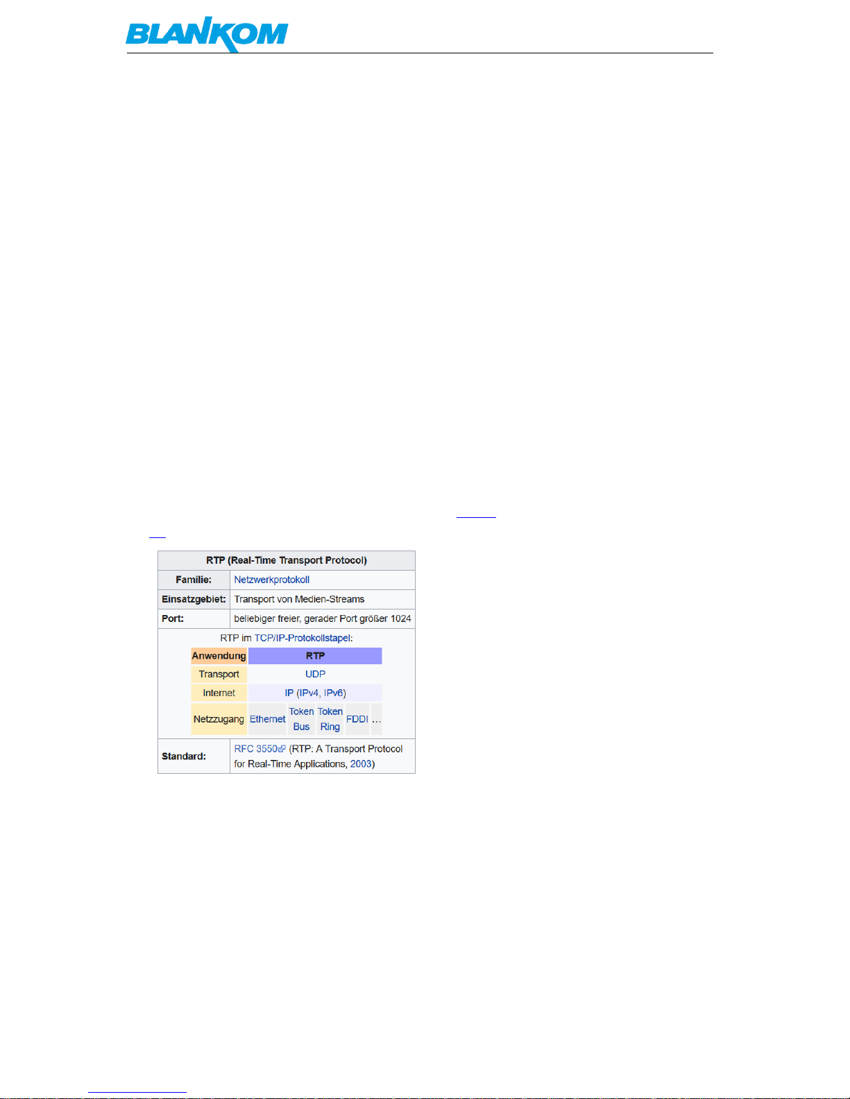
RTP:
a part from: https://tools.ietf.org/html/rfc3550
Chapter 11:
RTP relies on the underlying protocol(s) to provide demultiplexing of
RTP data and RTCP control streams. For UDP and similar protocols,
RTP SHOULD use an even destination port number and the corresponding
RTCP stream SHOULD use the next higher (odd) destination port number.
For applications that take a single port number as a parameter and
derive the RTP and RTCP port pair from that number, if an odd number
Page 28
BLANKOM BTR-6000 Transcoder User Manual
Version 1.0 – 06-2018 Page - 28 -
is supplied then the application SHOULD replace that number with the
next lower (even) number to use as the base of the port pair. For
applications in which the RTP and RTCP destination port numbers are
specified via explicit, separate parameters (using a signaling
protocol or other means), the application MAY disregard the
restrictions that the port numbers be even/odd and consecutive
although the use of an even/odd port pair is still encouraged. The
RTP and RTCP port numbers MUST NOT be the same since RTP relies on
the port numbers to demultiplex the RTP data and RTCP control
streams.
In a unicast session, both participants need to identify a port pair
for receiving RTP and RTCP packets. Both participants MAY use the
same port pair. A participant MUST NOT assume that the source port
of the incoming RTP or RTCP packet can be used as the destination
port for outgoing RTP or RTCP packets. When RTP data packets are
being sent in both directions, each participant's RTCP SR packets
MUST be sent to the port that the other participant has specified for
reception of RTCP. The RTCP SR packets combine sender information
for the outgoing data plus reception report information for the
incoming data. If a side is not actively sending data (see Section
6.4), an RTCP RR packet is sent instead.
any port (even, not odd > 1024)
Page 29
BLANKOM BTR-6000 Transcoder User Manual
Version 1.0 – 06-2018 Page - 29 -
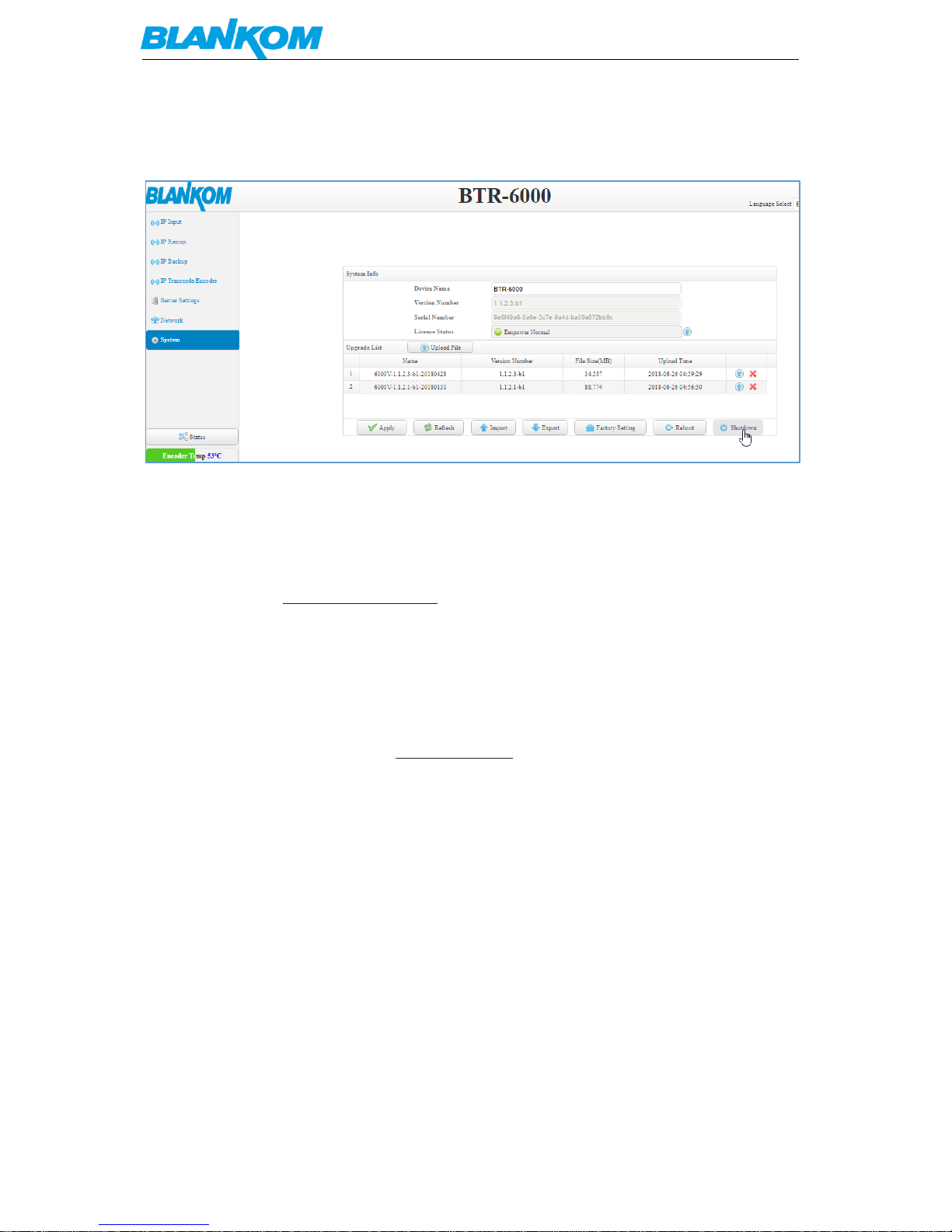
Remember:
Shutdown the unit always by its Shutdown button please:
If you only disconnect power, the unit can be damaged and maybe will show strange behaviors
after re-launching it.
Contact:
First Aid, Ralf Riedel: [email protected]
IRENIS GmbH
Owiesenkehre 1
D-22177 Hamburg - Germany
Managing Director: Dipl.Ing. Riccardo Rossini
Commercial Register: HRB 130657 / District Court Hamburg
Web: www.blankom.de E-Mail: [email protected]
Irenis-Direct Phone: +49 40 459747 Technical Hotline: +49 40 22864848
 Loading...