

Page 1
Professional Headend Solutions
Device manual
AMA 299
Part No: 9859.8x
QAM Modulator
ASI-TS → DVB-C/ ITU-T J.83 Annex B, C
Page 2

2
AMA 299
Part No: 9859.8x
QAM Modulator
ASI-TS → DVB-C/ ITU-T J.83 Annex B, C
ALINE
Contents
1. Safety and operating instructions .......................................................................................................... 3
2. Device variants .......... ............................................................................................................................. 3
3. General ........................ ........................................................................................................................... 3
4. Functional description ............................................................................................................................ 3
5. Explanation of the operating elements ................................................................................................... 4
5.1 Front view ........ ................................................................................................................................ 4
5.2 Meaning of the LED signals ............................................................................................................. 4
5.3 Front panel keypad and tuning wheel ............................................................................................. 4
5.4 Rear view ....... .................................................................................................................................. 5
5.5 9-pin D-SUB connector configuration (alarm contact) .................................................................... 5
6. Programming by web server ................................................................................................................... 6
6.1 Network connection to computer ..................................................................................................... 6
6.2 Device status .................................................................................................................................... 7
6.3 Standard settings ............................................................................................................................. 7
6.4 Extended settings ............................................................................................................................ 8
6.5 NIT table .......... ................................................................................................................................ 8
6.6 LCN configuration .......... .................................................................................................................. 8
6.7 Program filter .................................................................................................................................... 9
6.8 Software overview ............................................................................................................................ 9
6.9 IP network ........... ........................................................................................................................... 10
7. SNMP management ............................................................................................................................. 11
7.1 Download MIB ................................................................................................................................ 11
7.2 Trap messages ............................................................................................................................... 11
8. Menu structure of display handling ...................................................................................................... 12
9. Block diagram ........ .............................................................................................................................. 13
10. Technical data .... ................................................................................................................................ 13
11. Glossary ................... .......................................................................................................................... 14
12. Bibliography ........ ............................................................................................................................... 14
13. Document history ............................................................................................................................... 14
Page 3
3
AMA 299
Part No: 9859.8x
QAM Modulator
ASI-TS → DVB-C/ ITU-T J.83 Annex B, C
A
LINE
1. Safety and operating instructions
When assembling, starting-up and adjusting the modules, it is necessary to consider the system specific references in
the manual instruction.
The modules may only be installed and started up by authorized technical personne.
When assembling the modules into the receiving points, the adherence of the EMC regulations is to be secured.
The assembly and wiring have to be done without voltage.
With all work the defaults of the DIN EN 50083 have to be considered. Especially the safety relevant execution of the
DIN EN 60728-11 [3] is necessary.
The devices come under protection classification I. It is absolutely necessary, therefore, to insert the mains plug into a
socket with protective contact.
2. Device variants
AMA 299 9859.81 ASI - TS → DVB-C / ITU-T J.83 Annex B, C
9859.82 ASI - TS → IFI → DVB-C / ITU-T J.83 Annex B, C
3. General
The QAM Modulator AMA 299 is a module of the head end system A-LINE which is conceived as a complete system for big and
middle-sized networks.The module converts one digital transponder into the digital cable standard DVB-C, ITU-T J.83 Annex B or C.
The signal will be transcoded from the ASI transport stream into cable TV channels.
The status of the assembly will displayed with LED‘s (see section 5.2 ”Meaning of the LED signals”).
4. Functional description
The data stream which results from the ASI input is passed to a FIFO. All services of the resulting transport stream which shall be
processed into the QAM modulator will be choosen by controling software of the module. The SI and PSI tables affected (i.e. the PAT,
PMT, SDT, EIT, NIT) are automatically corrected. The changed SI an PSI tables are fed into the QAM modulator and an IF signal is generated at the output channel. There is a free choise of frequency in the output channel from 45 to 862 MHz. On the output side, the
modulator does not leak to adjacent channels. For level error reporting a reference level is generated internally and is compared with
current value permanently. After each programming of the level and/or frequency values an automatic measurement of the reference
level takes place. The integrated management unit consists of the data interface for PC/ LAN/ WAN (IP/ Ethernet interface / RJ 45).
The management of the module can be done via PC/Laptop (see programming).
The IP address of each device can be edited and adjusted to the respective LAN.
WEEE-Reg.-Nr. DE 50389067
Page 4
4
AMA 299
Part No: 9859.8x
QAM Modulator
ASI-TS → DVB-C/ ITU-T J.83 Annex B, C
ALINE
5. Explanation of the operating elements
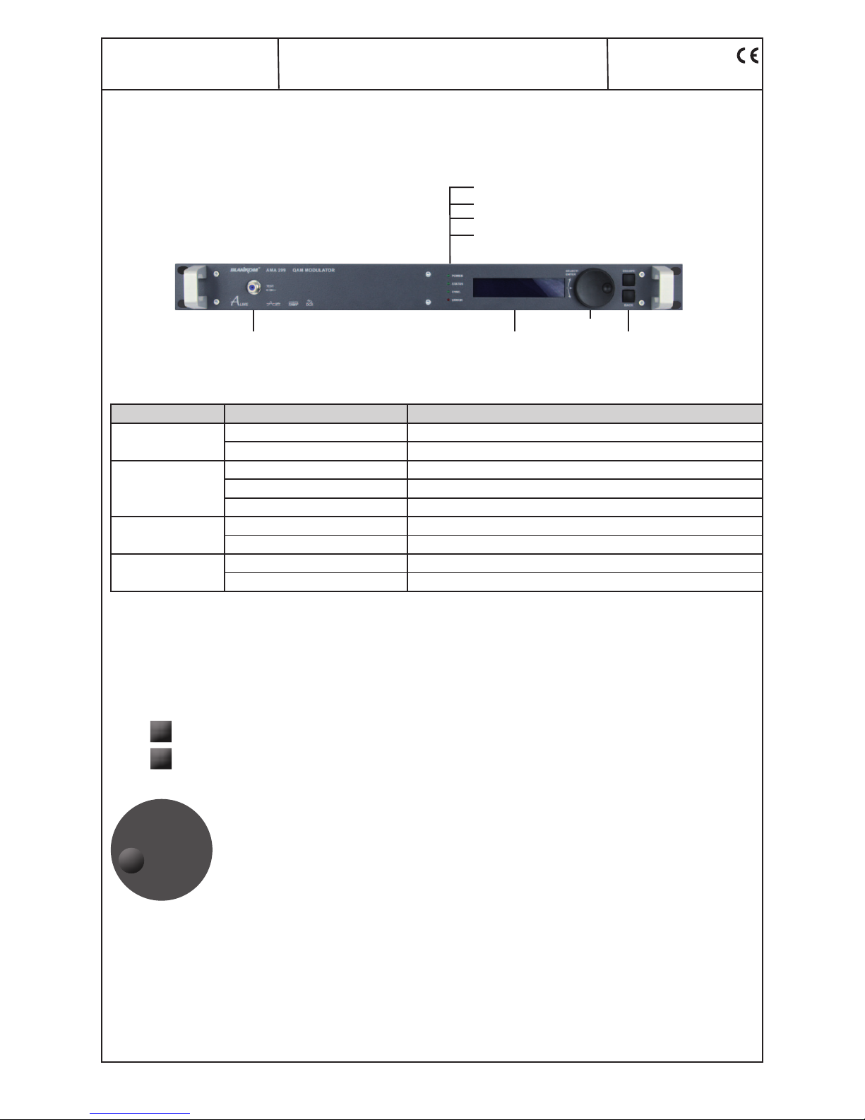
5.1 Front view
5.2 Meaning of the LED Signals
Designation (Colour) Status Meaning of display
POWER (green) permanently on Device is ready for working
off Device off, without current supply
STATUS (green) permanently on Device working, everything ok
flashing Dysfunction depending in signal (e.g. in case of invalid service)
off RF output is deactivated
SYNC. (green) permanently on ASI input is synchronous
flashing ASI not sync (e.g. in case of missing input signal)
ERROR (red) permanently on Device is on standby
flashing Device faulty (hardware)
5.3 Front panel keypad and tuning wheel
By activating the ESCAPE-Pad you exit the current menu cycle. The input function switches back to the inactive status and jumps to the status information (start display)
By activating the BACK-Pad you leave the current mode (menu selection) without any acceptance of settings
or adjustments. The cursor jumps one menu level higher.
Pressing of the tuning wheel is equivalent to the ENTER-Function.
The cursor switches to the active mode. Tuning the wheel right or left enables to select an menu entry, the
menu selection will be confirmed by pressing the wheel.
Each parameter function can be edited by pressing the tuning wheel (ENTER). By tuning the wheel you can
position the cursor to the desired selection. By pressing the tuning wheel (ENTER) you switch to the edit
mode. The text and/ or number positions can be individually selected by tuning the wheel. Pressing the wheel
(ENTER) confirms your input and switches back to the selection mode. After a complete and correct adjustment you have to position the cursor right to the symbol ↵ ENTER and confirm it by pressing the tuning
wheel. The display switches back to the selection mode of the parameter display.
POWER-LED
STATUS-LED
SYNC.-LED
ERROR-LED
Test (-30 dB) Display
ESCAPE
BACK
Keypad
Tuning wheel
Page 5
5
AMA 299
Part No: 9859.8x
QAM Modulator
ASI-TS → DVB-C/ ITU-T J.83 Annex B, C
A
LINE
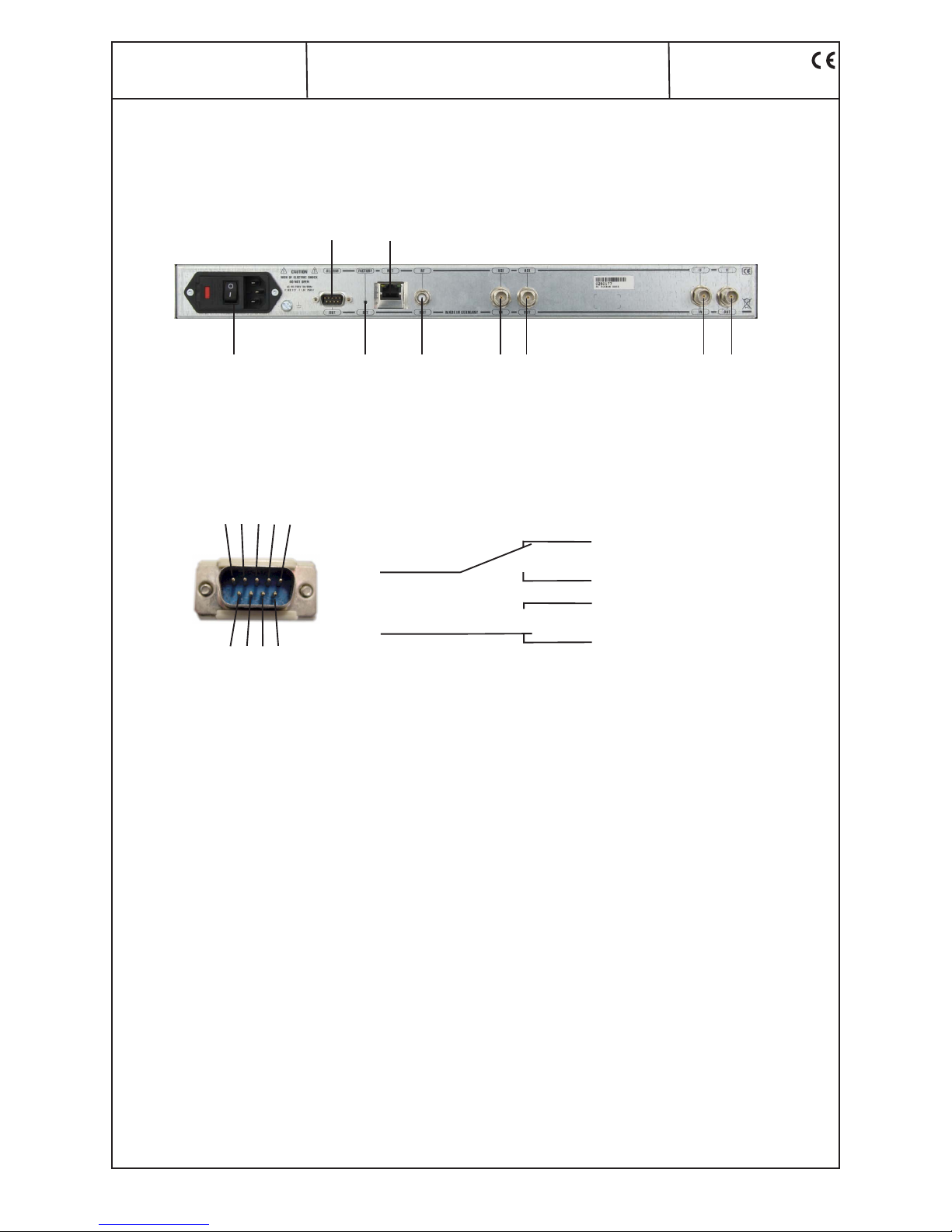
5.4 Rear view
*
only in device variant 9859.82 available
5.5 9-pin D-SUB connector configuration (alarm contact)
ALARM LAN/ WAN
Power Factory set RF out ASI-IN ASI-OUT IF-IN* IF-OUT
*
Alarm active:
Pin 8 and Pin 9 are closed
Pin 8 and Pin 7 are open
Normal operation
Pin 8 and Pin 9 are open
Pin 8 and Pin 7 are closed
1 2 3 4 5
6 7 8 9
Page 6
6
AMA 299
Part No: 9859.8x
QAM Modulator
ASI-TS → DVB-C/ ITU-T J.83 Annex B, C
ALINE
6. Programming by web server
6.1 Network connection to computer
System requirements:
- PC/ laptop with 10/ 100 Mbit Ethernet interface
- Internet browser (e.g. Windows internet explorer), which accept
JAVA-Script.
Setup the connection:
The AMA 299 must be connected to PC network using an Ethernet cable.
The IP address of the AMA 299 control port is 192.168.2.80 on delivery.
The address of the network connection at the compter must be adapted to
the IP address of the AMA 299 (subnet mask: 255.255.255.0, IP address:
192.168.2.XXX). Don`t be use the same combination lock for XXX like the
IP address of the AMA 299. The IP address of the AMA 299 is entered onto
the browser interface.
When the link up has been successfully made, the device starts with the
device status page.
The language (english/ german) can be selected on the right side of each
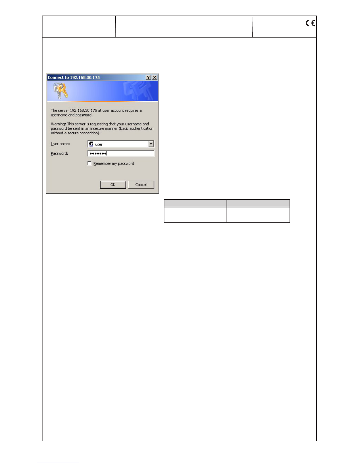
page. To change the settings of the device at the first user log-in window
will be open automatically.
The access to the configuration menu is password protected.
Access data (factory settings):
Registration details Valid string
User name user
Password password
After successful log-in the parameters can be modified.
The user log-in is only temporarily. The connection has to be refreshed
after some time.
Page 7
7
AMA 299
Part No: 9859.8x
QAM Modulator
ASI-TS → DVB-C/ ITU-T J.83 Annex B, C
A
LINE
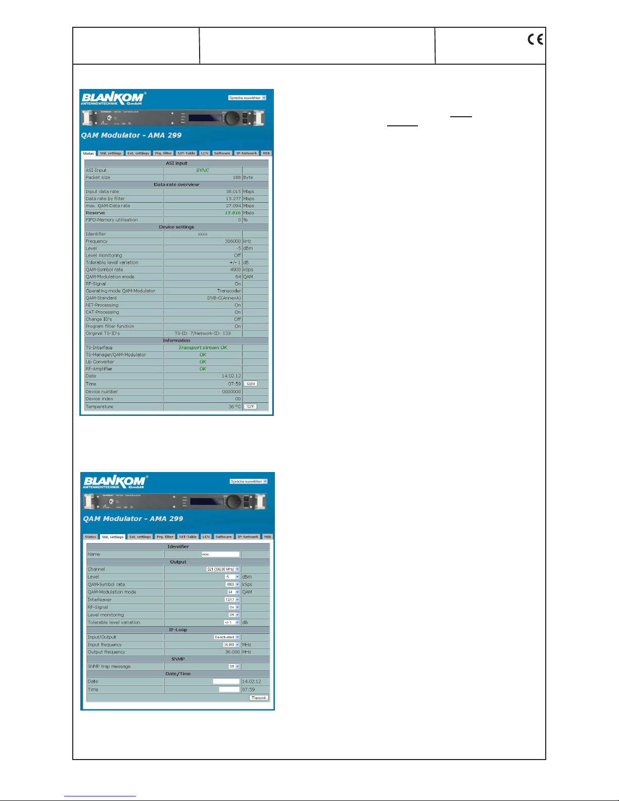
6.2 Device status
Choose language german, english
ASI input
ASI-Input ASI status display SYNChronisation or
noSYNChronisation with the input
Packet size in byte
Data rate overview
Input data rate used data rate at input
Data rate by filter used data rate after program filter
max. QAM-Data rate max. used data rate
Reserve max. QAM data rate minus data rate after
filter
FIFO-Memory utilisation displays in %
Device settings
Identifier e.g. program name acc. adjustments in 6.3
Frequency acc. adjustments in 6.3
Level acc. adjustments in 6.3
Level monitoring acc. adjustments in 6.3
Tolerable level variation acc. adjustments in 6.3
QAM-Symbol rate acc. adjustments in 6.3
QAM-Modulation mode acc. adjustments in 6.3
RF-Signal on/ off acc. adjustments in 6.3
Operating mode QAM-Mod. acc. adjustments in 6.4
QAM-Standard on/ off acc. adjustments in 6.4
NIT-Processing on/ off acc. adjustments in 6.4
CAT-Processing on/ off acc. adjustments in 6.4
Change ID‘s on/ off acc. adjustments in 6.4
Program filter function on/ off acc. adjustments in 6.4
Original TS-ID’s displays transport stream ID and network ID
Information
TS-Interface status of transport stream
TS-Manager/QAM-Modul. status of TS manager/ QAM modulator
Up Converter status of up converter
RF-Amplifier status of RF amplifier
Date acc. adjustments in 6.3
Time acc. adjustments in 6.3,
12/ 24-h-mode selectable
Device number display of the device number
Device index display of the device index (hardware)
Temperature temperature of device, °C/ F selectable
6.3 Standard settings
Choose language german, english
Identifier
Name independent text field for device identifica tion (max. 30 characters)
Output
Channel channel selction (2 ... 69, standard B/G)
Level adjustment range -10 ... +14 dBm
QAM-Symbol rate selection: 6995, 6900, 6875, 6111, 6000,
3450, 1750 kSps
QAM-Modulation mode selection: 16, 32, 64, 128, 256 QAM
Interleaver selection: 12/17 (DVB-C/ Annex A)
12/17, 8/16, 16/8, 32/4, 64/2, 128/1,
... , 128/8 (ITU-T J.83 Annex B)
12/17 (ITU-T J.83 Annex C)
RF-Signal selection: on/ off
Level monitoring selection: on/ off
Tolerable level variation selection: ± 1 dB ... ± 5 dB, 0.5 dB steps
IF-Loop
Input/ Output selection: Activated/ Deactivated
Input frequency selection: 36.000, 36.125, 36.150, 38.900,
44.000, 45.750 MHz
Output frequency 36.000 MHz
SNMP
SNMP trap message on/ off /locked (if not supported by software)
Date/ Time
Date input format: dd.mm.yy
Time input format: hh:mm (AM/ PM)
Date/ Time input must be set to initialize
internal clock (after first start-up of device or
reinitializing after a longer shut-down).
Additional selection of AM/ PM in 12-h-mode.
Page 8
8
AMA 299
Part No: 9859.8x
QAM Modulator
ASI-TS → DVB-C/ ITU-T J.83 Annex B, C
ALINE
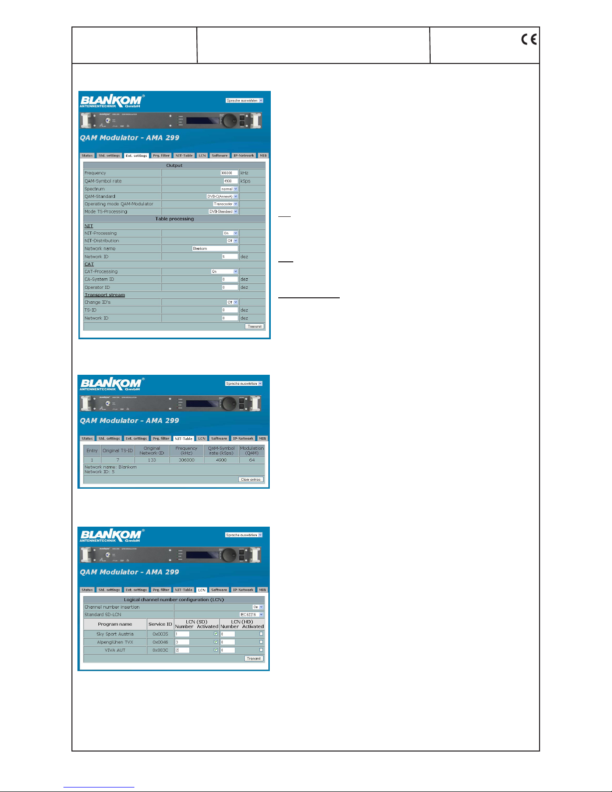
6.4 Extended settings
Choose language german, english
Output
Frequency adjustment range 45000...862000 kHz
QAM-Symbol rate adjustment range 1000...7200 kSps
Spectrum selection: normal/ invers
QAM-Standard selection: DVB-C (Annex A), ITU-T/J.83
(Annex B), ITU-T/J.83 (Annex C)
Operating mode QAM-Mod. selection: Transcoder, Testlevel,
Testsignal
Mode TS-Processing selection: DVB-Standard, TNT-France
Table processing
NIT
NIT-Processing activate or deactivate
NIT-Distribution activate or deactivate
Network name selectable (max. 30 characters)
Network ID selectable (0...65535)
CAT
CAT-Processing activate or deactivate
CA-System-ID selectable (0...65535)
Operator-ID selectable (0...65535)
Transport stream
Change ID’s activate or deactivate
TS-ID selectable (0...65535)
Network ID selectable (0...65535)
6.5 NIT table
Choose language german, english
NIT table with all additional entered informations.
By clicking the button “Clear entries“ all NIT entries are cleared.
6.6 LCN configuration
Choose language german, english
The allocation of a logical channel number (LCN) is a service that
allocates a serial number to each TV activated program. If the settop
box supports this service at the subscriber, the TV programs are
offered in the order established by program numbers. It should be
noted that the numbering is done separately for HD and SD programs
for the respective type of the box. The simultaneous activation and
number allocation for SD programs in the HD column provides such
programs to the appropriate channel number in the program list for
HD boxes.
Page 9
9
AMA 299
Part No: 9859.8x
QAM Modulator
ASI-TS → DVB-C/ ITU-T J.83 Annex B, C
A
LINE
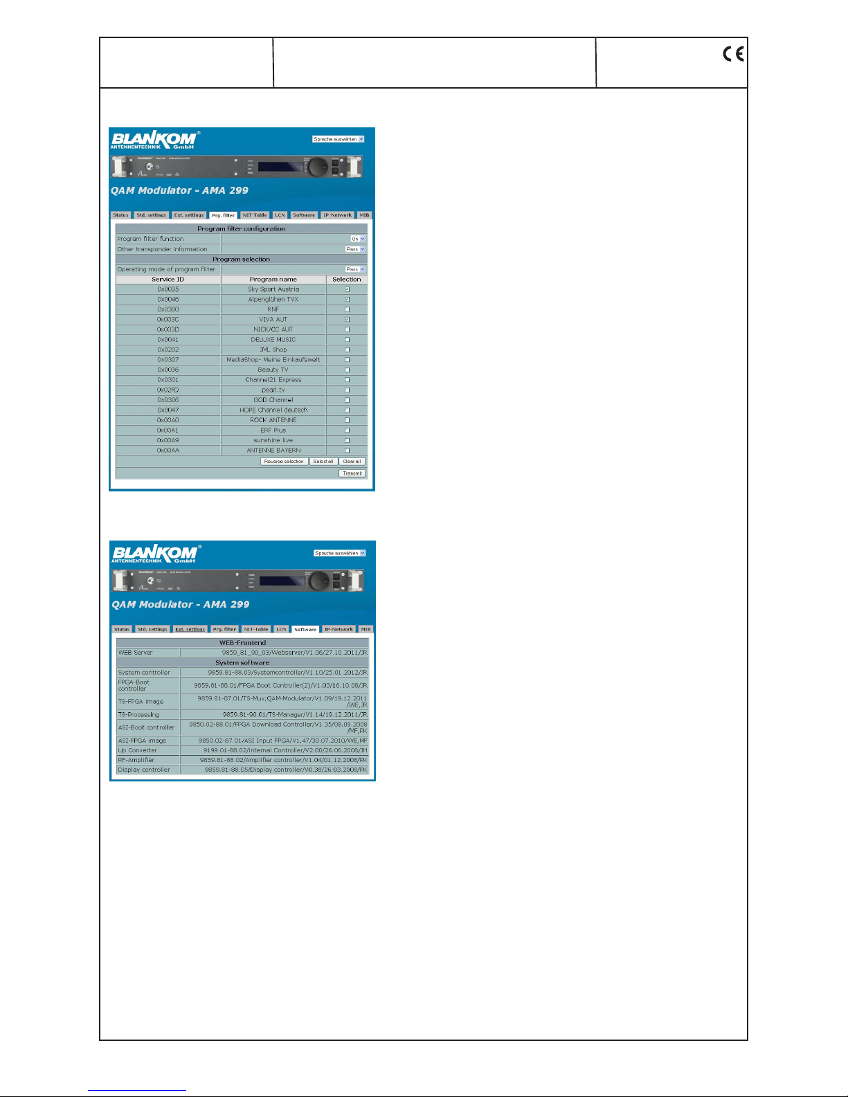
6.7 Program filter
Choose language german, english
Program filter configuration
Program filter function activate or deactivate
Other transponder
information pass or drop of additional informations
(e.g. electronic program guide), which are
contained in data stream as “other“
Program selection
Operating mode program
filter pass or drop of the market programs
Reserve selection all not marked programs are choosen
or vice versa
Select all all programs of the list are marked
Clear all no program the list is marked
6.8 Software overview
Choose language german, english
Software versions:
WEB-Frontend
WEB Server
System software
System controller
FPGA-Boot controller
TS-FPGA image
TS-Processing
ASI-Boot controller
ASI-FPGA image
Up Converter
RF-Amplifier
Display controller
Page 10
10
AMA 299
Part No: 9859.8x
QAM Modulator
ASI-TS → DVB-C/ ITU-T J.83 Annex B, C
ALINE
6.9 IP network
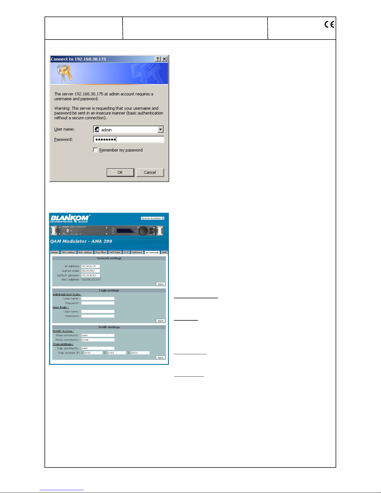
Selecting this menu at first the administrator log-in window
will be open automatically.
Following successful log-in the network and log-in settings
can be changed.
Choose language german, english
Factory settings are:
Network settings
IP-Address: 192.168.2.80
Subnet mask: 255.255.255.0
Default gateway: 192.168.2.1
MAC-Address: display of MAC address
Login settings
Administrator login:
User name: admin
Password: password
User login:
User name: user
Password: password
SNMP-Settings
SNMP-Access:
Read community: public
Write community: public
Trap settings:
Trap community: public
Trap receiver IP 1 0.0.0.0
2 0.0.0.0
3 0.0.0.0
• Administrator- and/ or user-login can be deactivated by clearing of user
name and password.
• The addresses must be matched to the respective network.
Page 11
11
AMA 299
Part No: 9859.8x
QAM Modulator
ASI-TS → DVB-C/ ITU-T J.83 Annex B, C
A
LINE
7. SNMP management
7.1 Generate MIB
Choose language german, english
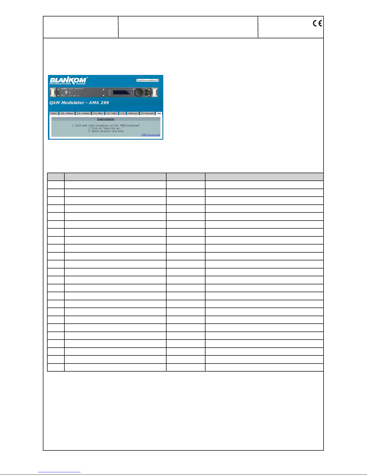
The complete MIB for an AMA 299 can be downloaded like descriped
under “Instructions“ on this website and clicking the “MIB Download” link.
With the aid of an MIB browser, the relevant one can be decided upon and
taken over to control the device via a network and/ or an SNMP manager
capable of SNMPv2c
7.2 Trap messages
Item Message Message type Explanation
01 Power Fail CRITICAL short circuit
02 System Reset WARNING reset by internal error
03 Signal ok INFORMATION module works correctly
04 ASI input not sync WARNING no input signal at the ASI input
05 IIC error CRITICAL IIC bus error
06 TS-MUX not sync WARNING no transport stream at the FPGA
07 Internal controller reset WARNING error when accessing internal controller
08 FPGA: Program memory full WARNING overflow of program memory in the FPGA
09 FPGA: PID memory WARNING overflow of PID memory in the FPGA
10 FPGA: Directory full WARNING overflow of directory in the FPGA
11 FPGA: FAT memory full WARNING overflow of FAT memory in the FPGA
12 FPGA: TS-Packed buffer overflow WARNING overflow of TS packet buffer
13 QAM overflow CRITICAL overflow of QAM
14 Sync error data FIFO CRITICAL data FIFO doesn’t work correctly
15 No response to OPEN command CRITICAL error internal port
16 Up Converter: PLL1 not locked CRITICAL no funktion at the PLL 1 converter
17 Up Converter: PLL1 not locked CRITICAL no funktion at the PLL 2 converter
18 Up Converter: IF input too small WARNING IF level at Up converter input too smal
19 Up Converter: IF input too large WARNING IF level at Up converter input too large
20 UP Converter: IF input ok INFORMATION IF level at Up converter input ok
21 Amplifier: RF Level too large WARNING RF level at amplifier too large
22 Amplifier: RF Level too small WARNING RF level at amplifier too smal
23 Amplifier: RF Level ok INFORMATION RF level at amplifier ok
24 ASI input sync INFORMATION signal at ASI input ok
Page 12
12
AMA 299
Part No: 9859.8x
QAM Modulator
ASI-TS → DVB-C/ ITU-T J.83 Annex B, C
ALINE
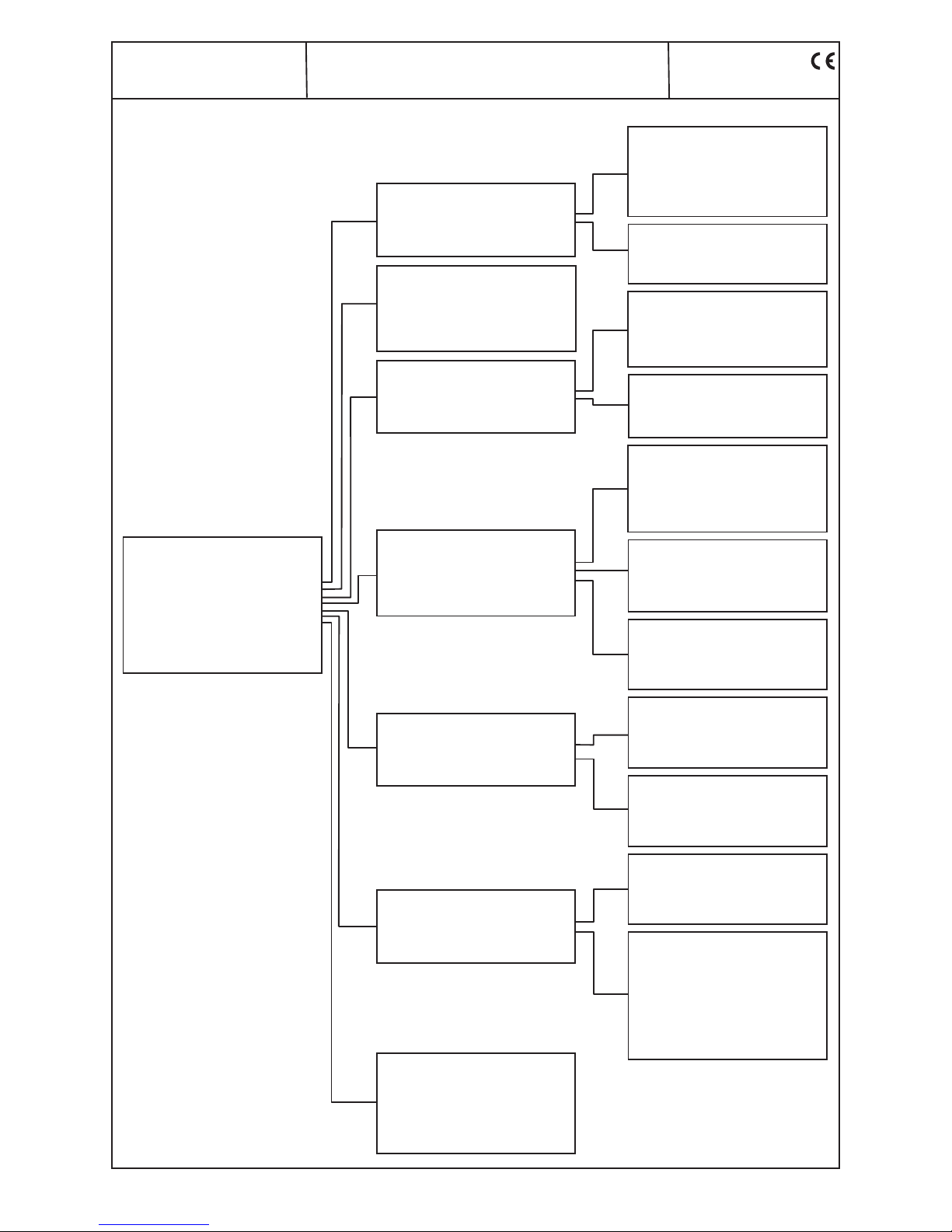
8. Menu structure of display handling
Main menu
RF output
IF loop
QAM modulator
Table processing
Program filter
Communication
System
Quit
RF output
Configuration
Settings
Back
QAM modulator
Configuration
Settings
Back
Table processing
NIT
CAT
TS
Back
Program filter
Configuration
Program selection
Back
Communication
Ethernet
SNMP
Back
System
Description: AMA 299
Language: English
Time: 12:00
Date: 01.01.2009
Back
RF output → Configuration
RF signal: On
Level monitoring: Off
Level variat. (dBm): ± 1
IF input/ output: Deactivated
Back
QAM modulator → Configuration
QAM standard: DVB-C (Annex A)
Operating mode: Transcoder
Spectrum inversion: normal
Back
Table processing → NIT
Processing: Off
Distribution: Off
Network name: BLANKOM
Network ID: 00000
Back
RF output → Settings
Frequency (kHz): 306000
Level (dBm): +14
Back
QAM modulator → Settings
Symbol rate: 6900
Modulation: 64
Back
Table processing → CAT
Processing: Off
CA system ID 00000
Operator ID 00000
Back
Table processing → TS
Change IDs: Off
TS ID: 00000
Network ID: 00000
Back
Program filter → Configuration
Filter function: Off
Operating mode: Drop
TS Information: Pass
Back
Program filter → Progr. selection
# 0x0046/ Alpenglühen
# 0x0035/ Premiere Austria
0x0202/ TIER.TV
Back
Communication → Ethernet
IP address: 192.168.002.080
Subn.mask: 255.255.255.000
Gateway: 192.168.002.001
Back
Communication → SNMP
Trap messages: On
Read Community: public
Write Community: private
Trap Community: public
Trap IP1: 000.000.000.000
Trap IP2: 000.000.000.000
Trap IP3: 000.000.000.000
Back
IF loop
Input/ output Deactivated
Input frequency 36.000
Back
Page 13
13
AMA 299
Part No: 9859.8x
QAM Modulator
ASI-TS → DVB-C/ ITU-T J.83 Annex B, C
A
LINE
10. Technical data
ASI input
Level range 200 … 880 mV
pp
Connector BNC socket
Impedance 75 Ω
ASI polarity regular/ inverted
ASI output
Level 800 mVpp (± 10 %)
Connector BNC socket
Impedance 75 Ω
ASI polarity regular
ASI signal processing
Data rate 0.625…213 Mbps
ASI transfer format
Input/ output continuous, burst/ burst
TS transfer format
Input/ output 188, 204 byte (respectively)
Signal processing EN 50083-9 [1]
QAM modulator
Symbol rate 1.0 ... 7.2 MSps
QAM modulation ITU-T J.83 Annex B, C, DVB-C
Annex B Annex C DVB-C
QAM constell. 64; 256 64 16; 32;64;
128; 256
Roll off 12 %, 18 % 13 % 15%
Interleaving Conv. I=128, J=4 Conv. I=12 Conv. I=12
Forward error Reed Solomon (128,122) Reed Solomon Reed Solomon
correction (FEC) + Trellis (204, 188,8) (204, 188,8)
Test signals according adjustment symbol rate
& QAM constellation
Measurement signal unmod. carrier (signal level)
PSI-/ SI processing disconnectable
Zero stuffing continously
Signal processing EN 300 429 [2] (DVB-C)
ITU-T J.83[4] (Annex B, C)
IF loop
*
Output/ input internal jumpered or external avail able (switchable)
Output frequency 36.000 MHz
Input frequency 36.000, 36.125, 36.150, 38.900,
44.000, 45.750 MHz
Output/ input level - 14 dBm (95 dBµV)
Connector 2x BNC socket, 75 Ω
IF decoupling ≥ 80 dB
RF output
Output frequency range 45 ... 862 MHz
Tuning step 10 kHz / 25 kHz
**
Max. output level 14 dBm (123 dBµV)
Level adjustment range -10 ... +14 dBm
Channel allocation adjacent channel ability
Connector F socket, 75 Ω
Return loss ≥ 18 dB 45 MHz
- 1.5 dB/ octave
Test output - 30 dB (± 1 dB)
Signal quality
MER ≥ 43 dB (14 dBm)
≥ 45 dB (11 dBm)
Shoulder attenuation ≥ 50 dB (14 dBm)
≥ 58 dB (11 dBm)
Spurious 45...862 MHz ≥ 60 dB (14 dBm)
≥ 63 dB (11 dBm)
C/N (> 25 MHz space from channel center)
BW = 6 MHz typ. 79 dB
BW = 8 MHz typ. 78 dB
Phase noise 1 kHz; typ. -92 dBc/ Hz
10 kHz; typ. -101 dBc/ Hz
100 kHz; typ. -108 dBc/ Hz
Max. frequency stability ± 30 kHz
Output level stability ± 0.5 dB (5 .. 45 °C)
Output level accuracy ± 1.5 dB
Amplitude frequency
response channel (8 MHz) max. 1 dB
pp
Operation parameters
Voltage/ current 100 ... 240 V ~ 50/ 60 Hz
100 ... 353 V =
Power consumption 18 W
Enviromental conditions
Temperature range -10 ... +55 °C
Temperature range
(for data keeping) 5 ... 45 °C
Relative humidity ≤ 80 % (non condensing)
Mounting location splash-proof
and drip-proof
Miscellaneous
Dimensions (w x h x d) 448 x 44 x 350 mm
Weight 4,200 g
Delivery content 1x Power cord
1x RJ45 connection cable
1x Mounting kit
2x Fuse T 1A/ 250V
*
only in device variant 9859.82 available
**
25-kHz-step only with active IF loop and 36.125 MHz input frequency
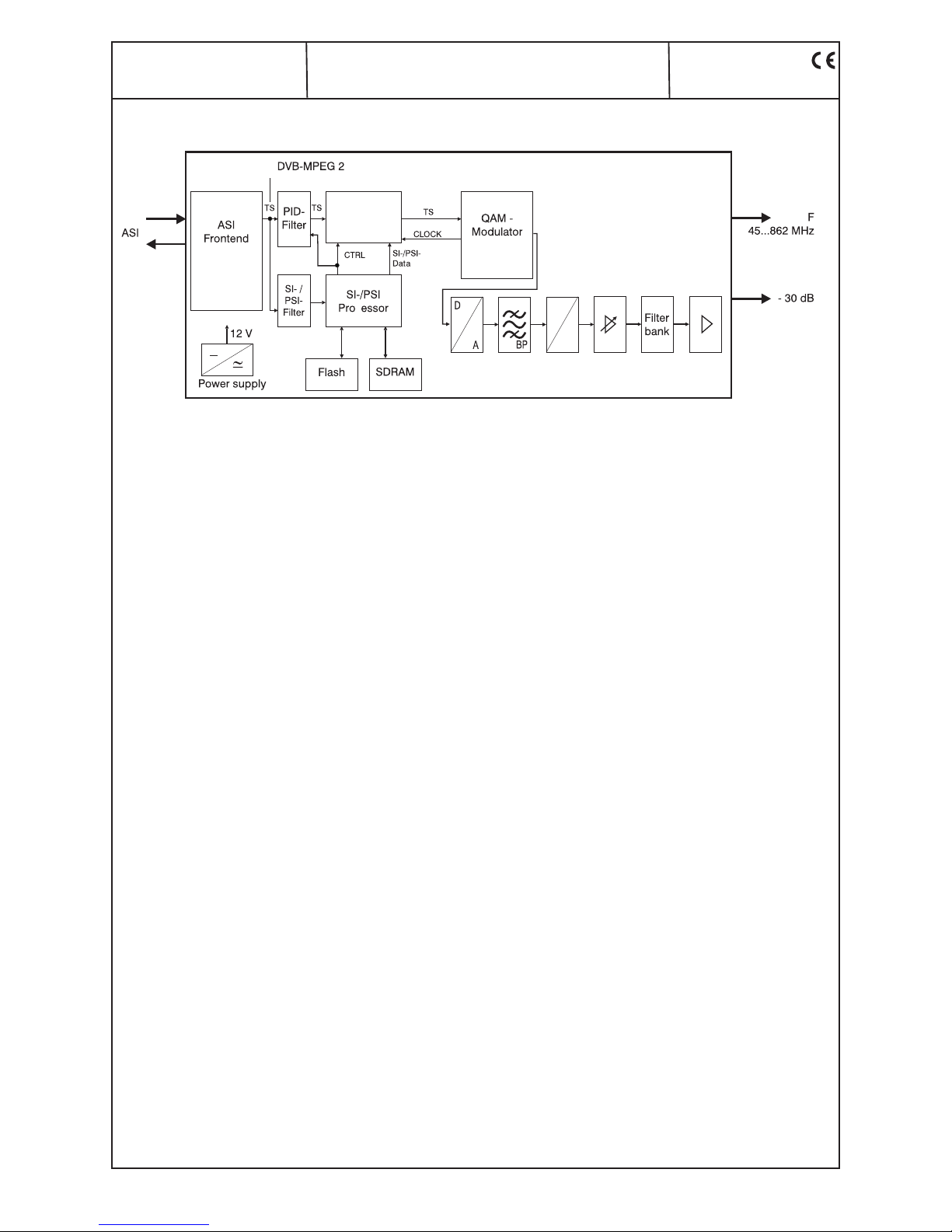
9. Block diagram
Multiplexer
with
PCR-correct.
c
IF
RF
RF measurement
socket
R
Page 14
14
AMA 299
Part No: 9859.8x
QAM Modulator
ASI-TS → DVB-C/ ITU-T J.83 Annex B, C
ALINE
11. Glossary
ASI Asynchronous Serial Interface
BW Bandwidth
CA Conditional Access
CAT Conditional Access Table
DVB Digital Video Broadcasting (-C Cable, -S Satellite, -S2 Satellite 2, -T Terrestrial)
EIT Event Information Table
ETSI European Telecommunications Standards Institute
FAT File Allocation Table
FEC Forward Error Correction
FIFO First In–First Out
FPGA Field Programmable Gate Array
HTML Hypertext Markup Language
HTTP Hypertext Transfer Protocol
I/Q In-phase/ Quadrature-phase
ID Identifier
IF Intermediate Frequency
IFI Intermediate Frequency Interface
IIC Inter-Integrated Circuit (I²C bus, data bus within device)
IP Internet Protocol
LED Light Emitting Diode
MAC Media Access Control
MER Modulation Error Ratio
MIB Management Information Base
MPEG Moving Picture Experts Group
NIM Network Interface Module
Nios Product name of a processor
NIT Network Information Table
PAT Program Association Table
PCR Program Clock Reference
PID Program Identifier
PMT Program Map Table
PSI Program Specific Information
QAM Quadrature Amplitude Modulation
RF Radio Frequency
SDT Service Description Table
SI Service Information
SNMP Simple Network Management Protocol
TS Transport Stream
12. Bibliography
[1] EN 50083-9: Cabled distribution systems for television, sound and interactive multimedia signals, part 9: Interfaces
for CATV/ SMATV head ends and similar professional equipment for DVB/ MPEG-2 transport streams
[2] EN 300 429: Digital Video Broadcasting (DVB): Framing structure, channel coding and modulation for cable systems
[3] EN 60728-11: Cable networks for television signals, sound signals and interactive services Part 11: Safety
(IEC 60728-11:2005); German version EN 60728-11:2005
[4] ITU-T J.83 Digital multi-programme systems for television, sound and data services for cable distribution, Amend ment to Annex B and C (2006)
[5] RFC 1157 Request for Comments (RFC): RFC Database URL: Http://www.rfc-editor.org/rfc.html
13. Document history
Version Date Modification Author
1.00 16.01.2009 basic dokument Rudolph
1.01 07.04.2009 revision Rudolph, Häußer
1.02 06.10.2009 revision (chapter 6.3) Häußer
1.03 15.03.2011 revision (chapter 10) Häußer
1.04 14.02.2012 revision websites (LCN) Häußer
Options and other TV standards available upon request! Subjects to changes due to technical progress.
BLANKOM Antennentechnik GmbH
Hermann-Petersilge-Straße 1 • 07422 Bad Blankenburg • Germany • Phone +49 (0) 3 67 41 / 60-0 • Fax +49 (0) 3 67 41 / 60-100
Page 15

15
Declaration of Conformity
The Manufacturer
BLANKOM Antennentechnik GmbH ∙ Hermann-Petersilge-Str. 1 ∙ 07422 Bad Blankenburg ∙ Germany
herewith declares the conformity of the product group
Product name: QAM Modulator
Type: AMA 299
Product number: 9859.8x
according to the following regulations
EN 50083-2
EN 60728-11 (as far as relevant)
and additional device-specific regulations, enclosed above, which these products are subjected to.
Date: 25.02.2009
Signature:
Piero Kirchner
(Managing Director)
 Loading...