

Page 1
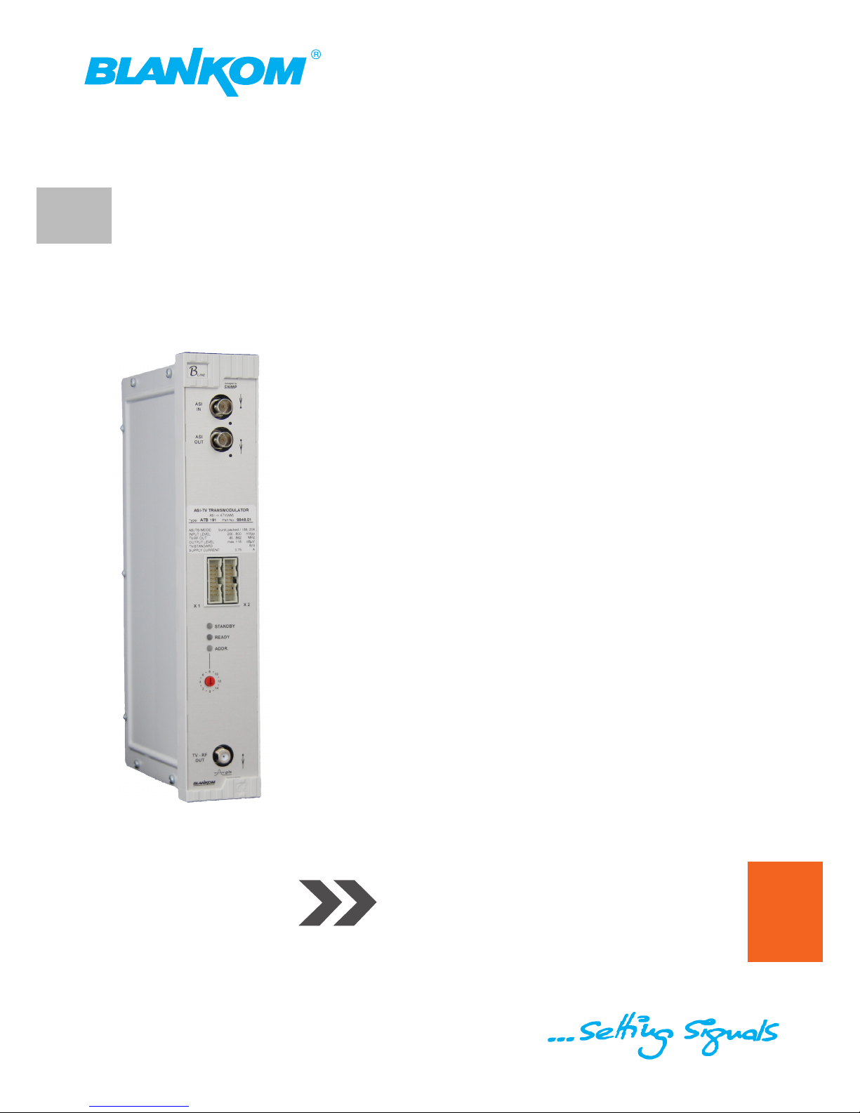
Professional Headend Solutions
Operating instructions
Contents
1. Safety and operating instructions ................................................................... 2
2. Device variants .. .............................................................................................. 2
3. General ............... ............................................................................................. 2
4. Front view ......................................................................................................... 3
5. Function description ........................................................................................ 3
6. Adjustments ................ .................................................................................... 3
6.1 Adjustment with the Headend Controller ..................................................3
6.2 Adjustment with the PC / laptop ................................................................3
7. Meaning of LED signals ................................................................................... 4
7.1 LED`s for the ASI ports ............................................................................ 4
7.2 LED`s on front panel ................................................................................ 4
8. Optional hardware variants ............................................................................. 4
8.1 IF interface ... ............................................................................................. 4
8.2 Additional A/V monitor outputs ................................................................. 5
9. Programming by Web server .......................................................................... 6
9.1 Main menu .............................................................................................. 6
9.2 Software options ....................................................................................... 6
9.3 Loading the programme list ...................................................................... 7
9.4 Extended settings ..................................................................................... 8
9.5 Manual settings ........................................................................................ 9
9.6 Factory settings .........................................................................................9
9.7 Status of device ...................................................................................... 10
10. Manual menu control at the Headend Controller ....................................... 11
11. Trap messages . ...........................................................................................11
12. Block diagram ............................................................................................ 12
13. Head end BUS structure .............................................................................. 12
14. Example of use ............................................................................................ 13
15. Technical data .. ........................................................................................... 13
16. Glossary .............................. ........................................................................ 14
17. Bibliography ..... ........................................................................................... 14
18. History ................ ......................................................................................... 14
ATB 19x
Part No: 9848.xx
ASI - TV Transmodulator
ASI → ATV (AM)
Page 2
2
ATB 19x
Part No: 9848.xx
ASI - TV Transmodulator
ASI → ATV (AM)
1. Safety and operating instructions
When assembling, starting-up and adjusting the modules, it is necessary to consider the system specific
references in the manual instruction!
The modules may only be installed and started up by authorized technical personnel!
When assembling the modules into the receiving points, the adherence of the EMC regulations is to be secured!
The assembly and wiring have to be done without voltage!
All active modules may only be operated with the Headend Controller HCB x00 or Bus Extender
BEB x00!
The main voltage and the operating voltage of the modules working by DC have to be in complience to the operating
parameters described in the technical data.
With all work the defaults of the DIN EN 50083 have to be considered! Especially the safetyrelevant execution of the
DIN EN 60728-11 [2] is necessary!
2. Device variants
ATB 191 9848.01 ASI → ATV (AM) standard B/G
ATB 191 9848.08 ASI → ATV (AM), A/V standard B/G
ATB 191 9848.09 ASI → IFI → ATV (AM) standard B/G
ATB 192 9848.21 ASI → ATV (AM) standard D/K 1*
ATB 192 9848.22 ASI → ATV (AM) standard D/K 2*
ATB 192 9848.24 ASI → ATV (AM), A/V standard D/K 2*
ATB 192 9848.25 ASI → ATV (AM), A/V standard D/K 1*
ATB 192 9848.28 ASI → IFI → ATV (AM) standard D/K 2*
ATB 192 9848.29 ASI → IFI → ATV (AM) standard D/K 1*
* D/K 1: standard D/K with sou nd carrie r 6,5 M Hz and 6,25 MHz
D/K 2: standard D/K with sound carrier 6,5 MHz and 5,74 MHz
Minimum software requirements for HCB x00:
9650.03: version 2.34**
9650.04/.05: version 3.18**
9652.01: version 3.23**
**) Updates: w ww.blankom.de
3. General
The ATB 19x ASI -TV transmodulators are components of the B-LINE head end system which has been designed as a complete
package for medium-sized distribution networks. They are components which select a programme from the ASI transport
stream and convert it into an analogue cable TV channel. All the components are programmed via a single central control unit and
thereafter each component will function independently. The status of the modules are displayed via LED’s (see chapter 7.2 „LED`s
on front panel“).
Page 3
3
ATB 19x
Part No: 9848.xx
ASI - TV Transmodulator
ASI → ATV (AM)
The manual instructions of the Headend Controller HCB x00 and the Bus Extender BEB x00 have to be considered!
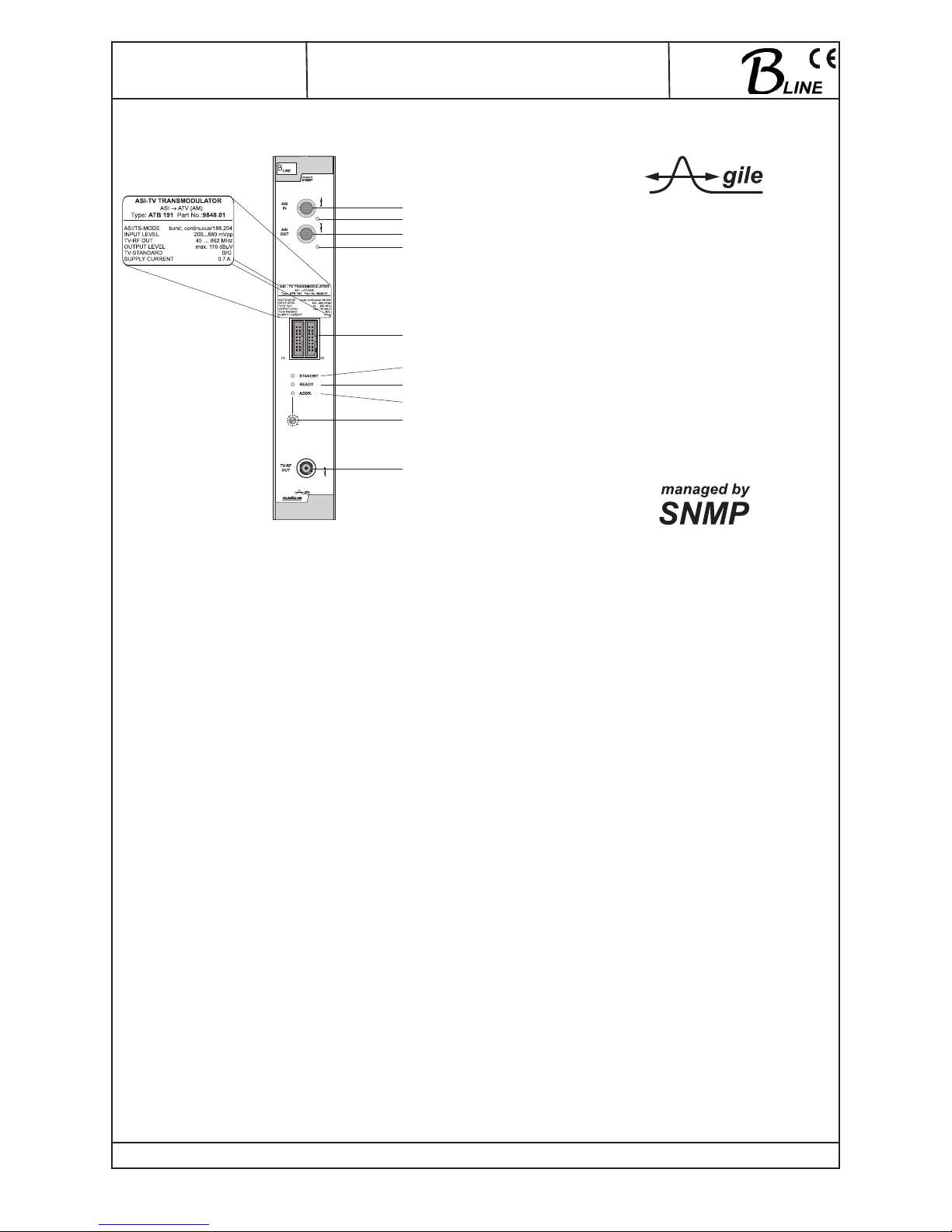
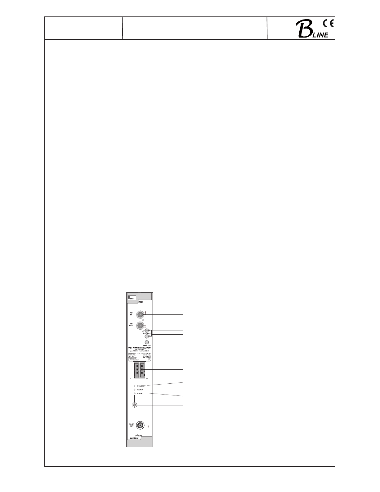
4. Front view
5. Function description
With this transmodulator, the digital ASI signal is decoded and then transferred into a serial data stream. Next, that data stream is
parallelised and fed into a FIFO system. The timing of this data input will in all cases be calculated from how full the FIFO system is
and adapted to the general data input rate. The regeneration system for the transport stream SPI protocol follows at the FIFO system
output, and at the same time, recognition of the transport stream being correct is ensured. It is at this level that the transport stream
can be edited.From the transport stream, the succeeding MPEG decoder selects a programme and generates an analogue video
signal and a digital audio signal. In the D/A converter which comes next; these two are converted into two analogue audio channels.
The analogue signals are fed into separate modulators and then aggregated in the IF (intermediate frequency) position. Then the
IF filtering takes place, and after that the production in the desired output channel. The fact that mixers are used which can accommodate a high output, also fractional N-PLLs, guarantees high-quality transmission. There is a free choice of frequency in the output
channel from 45 to 862 MHz. On the output side, the modulator does not leak to adjacent channels. If the output level changes, the
red LED will flash. Every time the level or frequency figures are programmed, automatic measurement of the reference level takes
place; his function will, however, not start until 100 seconds have elapsed after start-up of the system. When the output load changes
(perhaps because the output cable is disconnected), a warning and display item for a level fault may also appear. When the fault has
been identified, the appropriate SNMP Trap message will be sent. Use of this function is optional. By activation of the respective software option the services like test lines, the flash of subtitles and BISS decryption can be used.Supported are the BISS mode 1 and
the BISS mode E with input of the necessary Injected ID, but not the BISS mode E with the additional input of the optional Buried ID.
6. Adjustments
6.1 Adjustment with the Headend Controller
· Adjustment of the addresses at the Bus Extender BEB x00 and at the modules
· Activation of the programming mode of each module by selecting the line (BEB x00) and the module position (01... 15) at the
Headend Controller(HCB x00)
→ yellow LED will be lit up til the beginning of the parameter adjustment
· Adjustment of the ATB 19x parameter (see chapter 10) → green LED is lit up
· After the programming the ATB 19x will be automatically switched into the operating
→ yellow LED lights up briefly / green LED is lit up
6.2 Adjustment with the PC / Laptop
· Condition for the remote programming is an “online - connection” after IP - standard and an ethernet connection at the PC / Laptop
· Adjustment of the line / position addresses at the Bus Extender BEB x00 as well as at the modules
· At the Headend Controller HCB x00 IP - address input (e.g. 192.168.001.001)
· For “direct connection” between a PC and HCB x00 use a crossed patch cable (RJ 45)
· For connection over a deviation use an uncrossed patch cable
· HTML - browser start-up and put in IP - address as target address
· If connected correctly the HTML - control surface at the PC will open up and a blue LED (LINK) at the HCB x00 will be lit up).
· All adjustment of the modules are specified at the control surface.
ASI-TS input port
LED input
ASI-TS output port
LED output
Operating voltage/
control bus
“STANDBY“ LED (red)
“READY“ LED (green)
“ADDR.“ LED (yellow)
Adress selector switch
RF output for TV
Page 4
4
ATB 19x
Part No: 9848.xx
ASI - TV Transmodulator
ASI → ATV (AM)
7. Meaning of LED signals
7.1 LED`s for the ASI ports
Colour Status Meaning of display
green permanently illuminated ASI channel has been configured as input
flashing no ASI signal
yellow permanently illuminated ASI channel has been configured as output
flashing no ASI signal
7.2 LED`s on front panel
Designation (Colour) Status Meaning of display
STANDBY (red) permanently illuminated Component is on standby
flashing Component faulty (hardware) or level fault
READY (green) permanently illuminated Component working, everything ok
flashing error warnings, depending on signal:
- ASI without sync (e.g. when there is no input signal)
- service settings are not valid
- service is decrypted
ADDR. (yellow) illuminated or flashing remote control making contact / data being exchanged
8. Optional hardware variants
8.1 IF interface
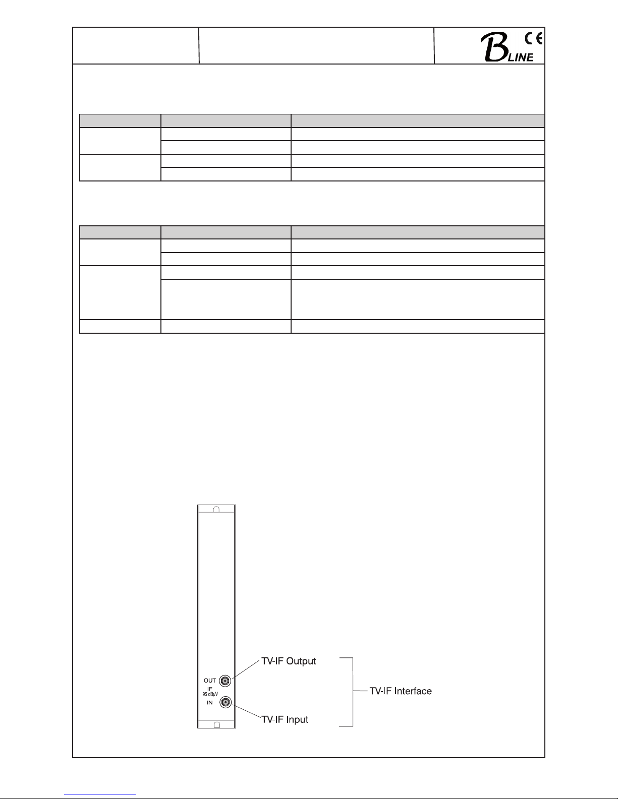
The IF interface is an optional additional function/equipment for the modules of the head end system B - LINE. The IF - interface separates the internal analogue TV- IF - signal - path and enables the lead out, the external processing and the re-feeding of the IF- signal
into the module.The connection sockets (type SMA) are located at the backside of the individual modules. The impedance is 75 Ohm.
The following device variants are equipped with an IF interface:
9848.09
9848.28
9848.29
View (back side of component)
Page 5
5
ATB 19x
Part No: 9848.xx
ASI - TV Transmodulator
ASI → ATV (AM)
Function description
The analogue TV - IF signal (picture and sound carrier) will be split after the main selection (SAW filter) and transported to the IF output socket. The processed signal will go from the IF input socket over an absorption- and adjustment unit directly to the upward
mixer. It has to be considered that no other channel selective filter stages are located in the input signal path and no level adjustments
and/or level control possibilities are available..
For the normal function of the interface, the conditions defined in the manual instructions have to be considered!
Operating instructions
1. The IF input level may only vary ±1 dB from the IF output level (95 dBμV). External IF modules may not change the level of the
signal and/or have to provide the necessary level at the output!
2. The external IF module, which is used for the processing and/or feeding of the IF signal, may not produce any spurious, which fall
below the necessary signal-to-noise ratio (>60 dB). If necessary, an additional IF filter has to be connected between the output of
the external module and the IF interface input..
3. If a module with IF interface is mounted to the wall, the usage of SMA angle plugs for the interface side of the connection cable is
recommended. The cables have to be screwed onto the interface socket before installing the module.
4. The connection cables and the plug connectors for the external IF modules, as well as their IF connections must have an impe dance of 75 ohm (e.g. RG 179 B/U with 75 ohm - BNC - plug connections).
5. To bypass the IF interfaces, the interface sockets have to be connected with a short cable (jumper). An internal module bypass
(e.g. by a jumper) is not possible!
Technical data
Output / input frequency (picture carrier analogue TV) 38,9 MHz
Frequency range 32,15 ... 40,15 MHz
Output / input level 95 dBμV
Impedance 75 Ω
Connector 2 x SMA socket
IF decoupling ≥ 80 dB
8.2 Additional A/V monitor outputs
These options have in comparison with the relevant basic variant a video output and two audio outputs for monitoring. The additional
outputs are located in the upper part of the front side and are implemented as MCX sockets.
The following device variants are equipped with additional A/V outputs:
9848.08
9848.24
9848.25
Front view
ASI-TS input port
LED input
ASI-TS output port
LED output
Audio output L,R
Video output
Operating voltage/
control bus
“STANDBY“ LED (red)
“READY“ LED (green)
“ADDR.“ LED (yellow)
Adress selector switch
RF output for TV
Page 6
6
ATB 19x
Part No: 9848.xx
ASI - TV Transmodulator
ASI → ATV (AM)
Technical data
Audio output 0,7 V
eff
at 10 kΩ
Connector MCX socket
Video output 1 Vss at 75 Ω
Connector MCX socket
9. Programming by Web server*
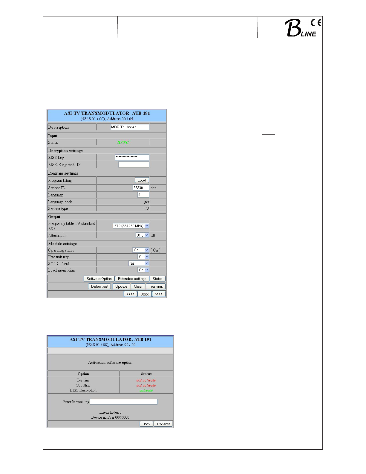
9.1 Main menu
Name of device, item number, address in head end
Description Name of programme (max. 30 characters)
Input
Status display wether SYNChronization or
noSYNChronisation with Input
Decryption settings
(will only be available if “BISS decryption” option is on)
BISS key input of the 12-digit code in BISS mode 1
or of the 16-digit code in BISS mode E
BISS-E injected ID input of the 14-digit code in BISS mode E,
no input in BISS mode 1!
Program settings
Program listing see Menu 2
Service ID freely selectable (0...65535)
Language freely selectable (0...255)
Language code shows the code for the language selected
Service type shows the type of service selected
(TV, radio)
Output
Frequency table channel selection:
standard B/G channel 2..69
standard D/K channel R1.. 69
Attenuation adjustment range 0 ... 31.5 dB
Module settings
Operating status selection: On, Off, Reset
Transmit trap On/Off, if SNMP option in HCB x00
enabled,otherwise “locked“ display
SYNC check checks SYNC at input port. selection:
fast, normal, slow
Level monitoring at output port. selection: On, Off
Routing to the appropriate adjustment menu:
Software option see menu 1
Extended settings see menu 3
Status see menu 6
Default set see menu 5
9.2 Software option (menu 1)
Name of device, item number, address in head end
Dialogue for entering code to activate the “test line”
(CKB 101), “subtitling” (CKB 102) and “BISS decryption”
(CKB 104) software options. When the page is called up, the
current state of activation for the relevant option will be displayed.
* Further details on this are to be found in the HCB manual
Page 7
7
ATB 19x
Part No: 9848.xx
ASI - TV Transmodulator
ASI → ATV (AM)
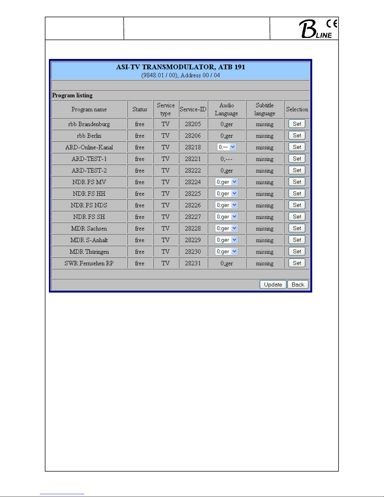
9.3 Loading the programme list (menu 2)
This menu contains a list of all services contained in the data stream. Language selection can take place here if available. Any service
is adopted or given new settings by clicking the relevant “Set” button.
Page 8
8
ATB 19x
Part No: 9848.xx
ASI - TV Transmodulator
ASI → ATV (AM)
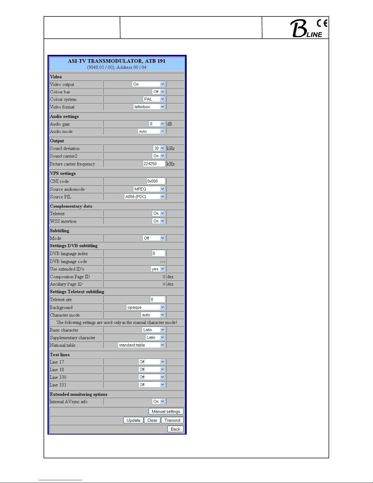
9.4 Extended settings (menu 3)
Name of device, item number, address in head end
Video for setting the video parameters
Video output selection: On, auto off, auto colour
palette bar
Colour bar selection: On, Off
Colour system selection: PAL, SECAM, NTSC
Video format selection: Letterbox,center cut,1:1,
pillarbox, 4:3 vertical cut, 20:9 letterbox
Audio settings
Audio gain adjustment range +6...-20 dB
Audio mode selection: auto, monoL, monoR, stereo,
dual, dual invers (2 sound carriers)
auto, monoL, monoR, monoL+R (only 1
sound carrier)
Output
Sound deviation selection: 30 kHz (2 sound carriers)
30 kHz, 50 kHz (only 1 sound carrier)
Sound carrier 2 selection: On, Off
Picture carrier frequency input in kHz, automatic
frequency rounding up or down to next 10 kHz on
adoption
VPS settings
CNI code freely selectable hex. (0x000…0xFFF)
Source audiomode selection: MPEG, A056(MPEG)
Source PIL selection: A056(PDC), A056, PDC,
TimerControlCode
Complementary data
Teletext selection: On, Off
WSS insertion selection: On, Off
Subtitling
(will only be available if “Subtitling” option is on)
Mode Selection: Off, Teletext, DVB
Settings DVB Subtitling
(will only be available if “Subtitling” option is on)
DVB languages index freely selectable (0...255)
DVB language code shows the code for the language
selected
Use extended ID‘s selection: yes, no
Composition Page ID shows the ID (decimal figure)
Ancillary Page ID shows the ID (decimal figure)
Settings Teletext subtitling
(will only be available if “Subtitling” option is on)
Teletext site freely selectable (0...65535)
Background selection: not transparent, semi-transpa
rent, transparent, black transparent
Character mode selection: auto, manual
The following parameters only apply if the manual mode has been selected for the font:
Basic character selection: Latin,Cyrillic-1,Cyrillic-2, Cyril lic-3, Arabic, Greek, Hebrew
Supplementary selection: Latin, Cyrillic, Arabic, Greek,
character Hebrew
National table selection: standard table, alternative
table, no country code, English, German,
Swedish, Italian, French,Spanish, Czech,
Rumanian, Polish, Estonian, Latvian,
Serbian, Turkish, Danish
Test lines
(will only be available if “Test lines” option is on)
Line 17 a test signal can be sent on all four of
Line 18 these lines,the signal selection is:
Line 330 off, CCIR17, CCIR 18, CCIR 330m,
Line 331 CCIR331, Sinus (x)/x, Ramp
Extended monitoring options
Internal AVsync Info display option on status page (menu 6),
selection: On, Off
Routing to the appropriate adjustment menu:
Manual settings see menu 4
Page 9
9
ATB 19x
Part No: 9848.xx
ASI - TV Transmodulator
ASI → ATV (AM)
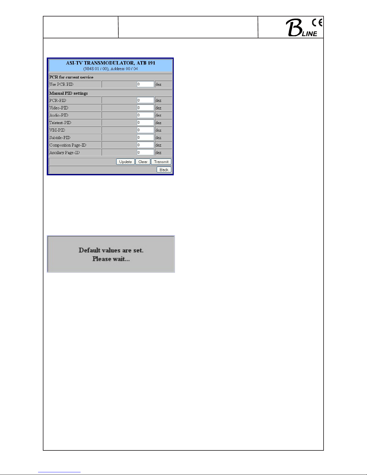
9.5 Manual settings (menu 4)
Name of device, item number, address in head end
PCR for current service
Use PCR PID freely selectable (0...65535))
Manual PID settings
PCR-PID freely selectable (0...65535)
Video-PID freely selectable (0...65535)
Audio-PID freely selectable (0...16383)
Teletext-PID freely selectable (0...65535)
VBI-PID freely selectable (0...65535)
Subtitle-PID freely selectable (0...65535)
Composition Page-ID freely selectable (0...65535)
Ancillary Page-ID freely selectable (0...65535)
9.6 Factory settings (menu 5)
When this menu is called up, all the settings made on the
EEPROM will be deleted and replaced by the default
settings. The modul will go back to these default values.
Once the setting process is over, there will be automatic
return to the main menu.
Page 10
10
ATB 19x
Part No: 9848.xx
ASI - TV Transmodulator
ASI → ATV (AM)
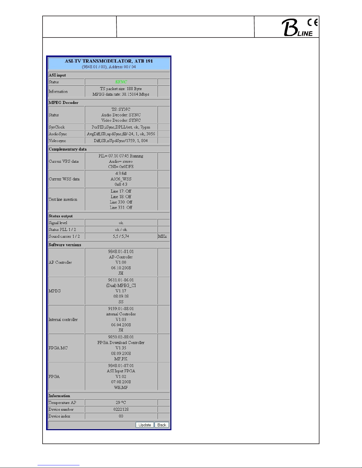
9.7 Status of device (menu 6)
Name of device, item number, address in head end
ASI input
Status synchronisation status
Information details of TS packet length and MPEG
data rate
MPEG Decoder
Status Synchronisation status for the TS and the
audio and video decoder
The following will only be displayed if the internal AVsync info
option is switched on (see menu 3)
SysClock details of system timing
AudioSync extended details of synchronisation sta tus of the audio decoder
VideoSync extended details of synchronisation sta tus of the video decoder
Complementary data
Current VPS data shows detailed information about
current VPS data
Current WSS data shows detailed information about
current WSS data
The following will only be displayed if the “test lines” option is switched
on:
Test line insertion Shows which test signal is set for the 4
lines
Status output
Signal level Shows status of signal level at output
(ok, too high, too low)
Status PLL1/2 Shows whether or not PLL1 (or PLL2) is
activated (ok, not ok)
Sound carrier 1/2 Shows frequency of sound carrier 1 or 2
Software versions
Shows the software versions for the controllers as follows:
- Controller of terminals board
- MPEG Controller
- Controller IF converter
- Download controller for FPGA ASI input
- FPGA ASI input
Information
Temperature AP Temperature of terminals board
Device number display of the device number
Device index display of the device index (hardware)
Page 11
11
ATB 19x
Part No: 9848.xx
ASI - TV Transmodulator
ASI → ATV (AM)
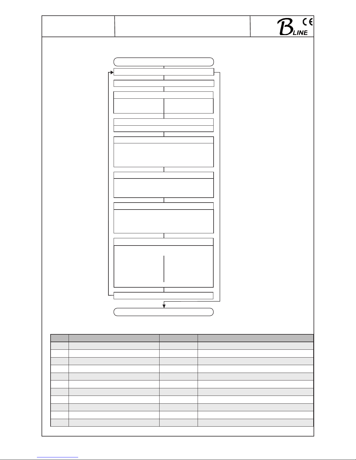
10. Manual menu control at the Headend Controller (HCB x00)
11. Trap messages
Item Message Message Typ Explanation
01 Signal OK INFORMATION Component working, everything ok
02 Input not sync WARNING Input not synchronised
03 MPEG Error CRITICAL MPEG error
04 System reset WARNING System has been reset after internal error
05 MPEG-Decoder not sync WARNING MPEG decoder not synchronised
06 Power fail CRITICAL Error in power supply
08 IIC Error CRITICAL Error in IIC or internal hardware
09 Output Signallevel too small WARNING Level of output signal too low
10 Output Signallevel too large WARNING Level of output signal too high
11 Output Signallevel ok INFORMATION Level of output signal ok
12 PLL error CRITICAL PLL at output not activated
ATB 19x start
Edit or Close
Power status On / Off
TV sound
Audio gain +6 ... -20 dB
Video settings
Video output On, auto off, auto colour palette bar
Colour system PAL, SECAM, NTSC
Colour bar On / Off
Video format Letterbox, center cut, 1:1, pillarbox,
4:3 vertical cut, 20:9 Letterbox
Additional data
Output
Output frequency 45000...862000 kHz
Output attenuation 0...31.5 dB
Sound carrier 2 Off Sound carrier 2 On
Sound deviation 30/50 kHz Sound deviation 30 kHz
Audio mode Audio mode
auto, mono L, auto, mono L,
mono R, mono L+R mono R, stereo,
dual,dual invers
Level monitoring On / Off
Channel name
ATB 19x end
Scan
No Yes
Service ID 0 .. 65535 Program selection
Audio - Index 0 .. 16383 Languages
VPS settings
VPS - CNI Code 0x000 ... 0xFFF
Source VPS Audio MPEG, A056(MPEG)
Source VPS - PIL A056(PDC), A056, PDC,
Timer Control Code,
Teletext On / Off
WSS insertion On / Off
Teletext site 0 .. 65535
Background
not transparent, semi-transparent,
transparent, black transparent
Page 12
12
ATB 19x
Part No: 9848.xx
ASI - TV Transmodulator
ASI → ATV (AM)
Item Message Message Typ Explanation
13 Tonmode Mono L+R INFORMATION Sound mode set as mono total
14 Tonmode Mono L INFORMATION Sound mode set as mono on left
15 Tonmode Mono R INFORMATION Sound mode set as mono on right
16 Tonmode Stereo INFORMATION Sound mode set as stereo
17 Tonmode Dual INFORMATION Sound mode set as dual
18 Tonmode Dual invers INFORMATION Sound mode set as dual inverse
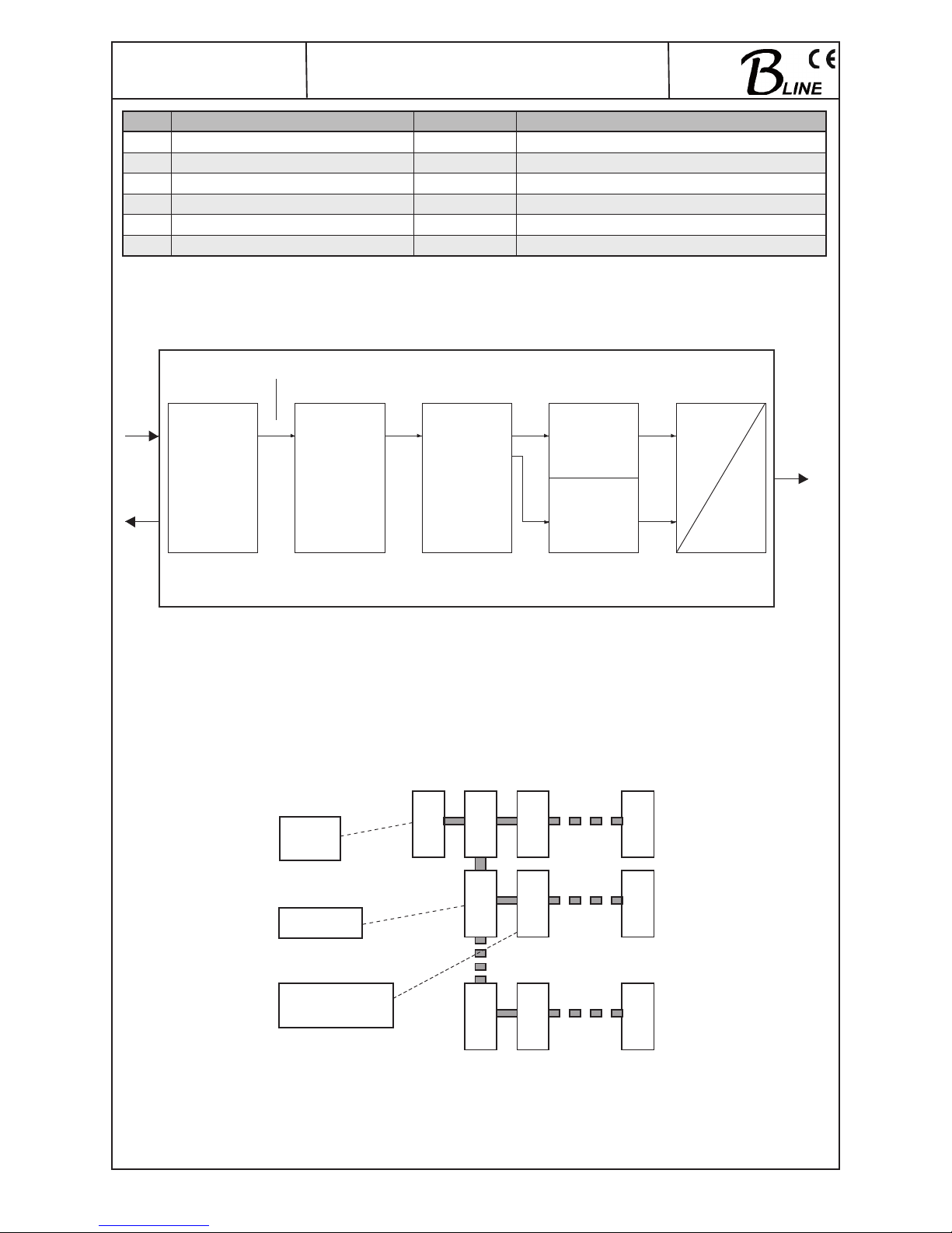
12. Block diagram
ASI
Frontend
MPEG-
decoder
Video/Audio-
processing
IF
RF
Vestigial
sideband
IF modulator
2x FM
modulator
ASI
RF
45...
862 MHz
DVB - MPEG 2
TSTS
13. Head end BUS structure
.
HCB x00
Headend
Controller
BEB x00
Bus Extender
Modul
signal processing
unit
HCB x00
Modul
ADDR. 15
BEB x00
ADDR. 01
BEB x00
ADDR. 02
BEB x00
ADDR. 15
Modul
ADDR. 01
Modul
ADDR. 01
Modul
ADDR. 01
Modul
ADDR. 15
Modul
ADDR. 15
The number of the possible module connections (00 ... 15) to a
BEB x00 depends on the total power consumption of this line!
Page 13
13
ATB 19x
Part No: 9848.xx
ASI - TV Transmodulator
ASI → ATV (AM)
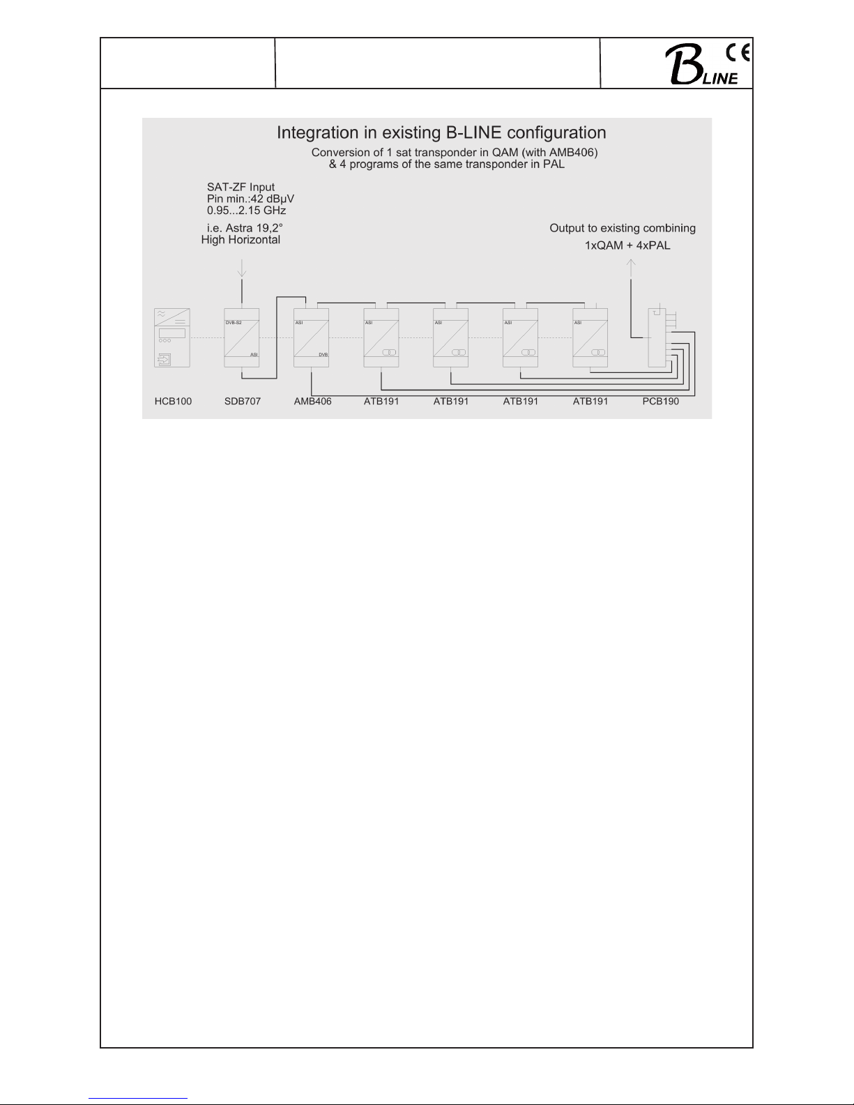
14. Example of use
15. Technical data
ASI input
Level range 200 … 880 mV
pp
Data rate 270 Mbps
Connector BNC socket
Impedance 75 Ω
ASI polarity regular/ inverted
ASI output
Level 800 mVpp (± 10 %)
Data rate 270 Mbps
Connector BNC socket
Impedance 75 Ω
ASI polarity normal
ASI signal processing
Data rate 0.625…78 Mbps
ASI transfer format
Input continuous, burst
Output burst
TStransfer format
Input 188, 204 Byte
Output 188, 204 Byte
Signal processing EN 50083-9 [1]
TV ouput
9848.01/.08/.09:
TV standard B/G
Sound carrier frequencies 5.5 / 5.742 MHz above pic.carr.
9848.21/.25/.29:
TV standard D/K
Sound carrier frequencies 6.5 / 6.25 MHz above pic.carr.
9848.22/.24/.28:
TV standard D/K
Sound carrier frequencies 6.5 / 5.742 MHz above pic.carr.
Sound type double carrier FM
Sound mode mono / stereo / dual /auto
(PDC controlled)
Audio deviation 1 mono – carrier 30 / 50 kHz
Audio deviation 2 mono - carrier 30 kHz
Audio deviation dual sound 30 kHz
Output frequency range 45 … 862 MHz
Tuning steps 10 kHz
Output level max. 116 dBμV
Range for level adjustment 0...31.5 dB (0.5 dB steps)
Channel allocation adj.channel compatible
Connector F socket
Impedace 75 Ω
Return loss ≥ 18 dB 45 MHz
-1.5 dB/ Octave
Signal quality
Single channel intermodulation ≥ 66 dB
Signal to noise ratio (S/N)
3rd order ≥ 60 dB
Spurious 45 ... 862 MHz ≥ 60 dB
C/N in channel (BW = 4.8 MHz) typ. 69 dB
C/N (> 25 MHz, distance from
centre of channel;BW=4.8 MHz) typ. 80 dB
S/N ratio parallel sound
unweighted/ weighted typ. 62/ 56 dB
Output level stability max.1 dB
pp
Frequency stability ± 30 kHz
Operating parameters
Current / voltage 12 V (0.2 V)/ 700 mA
Residual ripple of
supply voltage ≤ 10 mV
pp
Enviromental conditions
Temperature range -10 ... +55 °C
Temperature range for
data keeping 5 ... 45 °C
Relative humidity ≤ 80 % (non condensing)
Method of mounting vertical
Location of mounting splash-proof and
drip-proof
Physical information
Dimensions (l x w x h)
without 19” - adapter 50 x 276 x 148 mm
with 19” - adapter 50 x 301 x 148 mm
Weight 1,300 g
Delivery content
1 x BUS connector
Software options
Test lines CKB 101 (9650.51)
Subtitling CKB 102 (9650.52)
BISS decryption CKB 104 (9650.54)
Page 14
14
ATB 19x
Part No: 9848.xx
ASI - TV Transmodulator
ASI → ATV (AM)
16. Glossary
AM Amplitude modulation
AP Anschlussplatte (Terminals board)
ASI Asynchronous Serial Interface
ATV Analogue Television
AV Audio/Video
BISS Basic Interoperable Scrambling System
BW Bandwidth
CCIR Comité Consultatif International des Radiocommunications
C/N Carrier to Noise ratio
D/A Digital-/ AnalogDVB Digital Video Broadcasting (-C Cable, -S Satellit, -S2 Satellite 2, -T Terrestrial)
ETSI European Telecommunications Standards Institute
FIFO First In – First Out
FPGA Field Programmable Gate Array
HF Hochfrequenz
HTML Hypertext Markup Language
HTTP Hypertext Transfer Protocol
I/Q In-phase/Quadrature-phase
ID Identifier
IF Intermediate Frequency
IFI Intermediate Frequency Interface
IIC Inter-Integrated Circuit (I²C bus, data bus within device)
IP Internet Protocol
LED Light Emitting Diode
MC Microcontroller
MIB Management Information Base
MPEG Moving Picture Experts Group
NIM Network Interface Module
NTSC National Television Systems Committee
*
PAL Phase Alternating Line
*
PCR Program Clock Reference
PDC Program Delivery Control
PID Packed Identifier
PMT Program Map Table
PLL Phase-locked loop,
RF Radio Frequency
SECAM Séquentiel couleur à mémoire
*
SNMP Simple Network Management Protocol
SPI Serial Peripheral Interface
SPTS Single Program Transport Stream
TS Transport Stream
TV Television
VPS Video Programming System
WSS Wide Screen Signalling
*
colour-encoding systems of analogue television
17. Bibliography
[1] EN 50083-9: Cabled distribution systems for television, sound and interactive multimedia signals, part 9: Interfaces
for CATV/SMATV head ends and similar professional equipment for DVB/MPEG-2 transport streams
[2] EN 60728-11: Cable networks for television signals, sound signals and interactive services Part 11: Safety
(IEC 60728-11:2005); German version EN 60728-11:2005
[3] RFC 1157 Request for Comments (RFC): RFC Database URL: http://www.rfc-editor.org/rfc.html
18. History
Version Date Modification Author
1.00 18.07.2008 basic document Poch
1.01 26.02.2009 revision (BISS, options) Häußer
Options and other TV standards available upon request! Changes due to technical progress possible!
BLANKOM Antennentechnik GmbH
Hermann-Petersilge-Straße 1 • 07422 Bad Blankenburg • Germany • Telefon +49 (0) 3 67 41 / 60-0 • Fax +49 (0) 3 67 41 / 60-100
Page 15

15
Declaration of Conformity
The Manufacturer
BLANKOM Antennentechnik GmbH ∙ Hermann-Petersilge-Str. 1 ∙ 07422 Bad Blankenburg ∙ Germany
herewith declares the conformity of the product group
Product name: ASI - Transmodulator
Type: ATB 19x
Product number: 9848.xx
according to the following regulations
EN 50083-2
EN 60728-11 (as far as relevant)
and additional device-specific regulations, enclosed above, which these products are subjected to.
Datum: 25.02.2009
Unterschrift:
(Geschäftsführer)
 Loading...