

Page 1

1
Instruction Manual for
Blanco 90cm
Freestanding Induction
Cooker
FI905X
Page 2

2
Dear Customer,
Thank you for buying a BLANCO Freestanding Cooker.
Before we continue telling you about this oven, we cordially invite you to become
part of the Blanco family by subscribing online. Please visit our website where
you can easily register for product/cooking demonstrations, and request Blanco’s
gourmet recipes. Go to www.blanco-australia.com and fill in the subscription
details in the contact us/showrooms section.
You will find that the clean lines and modern look of your Blanco Freestanding
Cooker blends in perfectly with your kitchen décor. It is easy to use and performs to
a high standard.
Blanco also makes a range of products that will enhance your kitchen such as
ovens, cooktops, rangehoods, dishwashers, microwaves, sinks and taps. There are
models to complement your new Blanco Freestanding Cooker.
Of course, we make every effort to ensure that our products meet all your
requirements, and our Customer Relations department is at your disposal, to answer
all your questions and to listen to all your suggestions.
Please complete the warranty card and keep your receipt as proof of purchase.
Retain all documents relating to the purchase of this product.
Blanco is committed to providing increasingly efficient products that are easy to use.
Page 3
3
READ THE INSTRUCTION BOOKLET BEFORE INSTALLING AND USING THE APPLIANCE.
It is important that you retain these instructions, proof of purchase as well as
other important documents about this p roduct for future reference.
The manufacturer will not be responsible for any damage to property or to persons caused by
incorrect installation or imprope r use of the appliance.
Due to continual product development, Blanco reserves the right to alter specifications or
appearances without notice .
DO NOT OPERATE THIS AP PL I ANCE BEFORE READING THE
INSTRUCTION BOOK
DO NOT PLACE ARTICLES ON OR AGAINST THIS APPLIANCE
DO NOT STORE CHEMICALS OR FLAMMABLE MATERIALS OR
SPRAY AEROSOLS NEAR THIS APPLIANCE
DISPOSAL INFORMATION
• Most of the packing materials are recyclable. Please dispose of those materials
through your local recycling depot or by placing them in appropriate collection
containers.
• If you wish to discard this product, please contact your local authorities and ask for the
correct method of disposal.
Page 4

4
CONTENTS
PRODUCT DESCRIPTION
5
INSTALLER TECHNICAL INFORMATION
6
Installing the cooker 8
Room ventilation 8
Height adjustable legs 9
Anti-tilt system 10
Kick plate installation 12
Appliance electric connection 13
Appliance Maintenance 15
Replacing parts 16
USE AND MAINTENANCE INFORMATION
17
Using the induction hob 17
Induction Hob - zones descriptions 19
Types of pans 21
Safety Lock 23
Using the electric thermostat 24
Using the oven function knob 25
- Using the pre – heating function 26
- Using the pizza function 27
- Using the traditional function 27
- Using the fan assisted function 29
- Using the fan forced function 31
- Using the grill function 33
- Using the fan grill function 33
Key electronic programmer 34
Other functions 35
Cleaning the appliance 36
- Catalytic self - cleaning liners – rear and sides 36
- Removing oven door 37
- Removing of inside glass 37
- Removing of roof tray 38
Troubleshooting 39
Page 5

5
PRODUCT DESCRIPTION
90cm Freestanding Induction cooker
The following is a brief overview of all features that are evident in this product.
- Square stainless steel design
- 5 zones as follows:
• Rear zones right and central – 2300W, booster 3000W
• Front zones left and right – 1100W, booster 1400W
• Rear zone left – 1400W, booster 2000W
- Triple glazed thermo - reflective door
- Removable inner glass and door
- Extendable telescopic runners x 2
- Catalytic self-cleaning liners – rear and sides
- Fully programmable touch control timer
- Single welded energy efficient cavity
- 11 functions: Pre- heating, Top and bottom elements, Bottom element only, Top element only,
Full grill, Full grill with fan, Fan assisted, Fan forced, Bottom element with fan, Light, Defrost
- 4 shelves/rack levels
- Removable oven roof
- Ceramic hob
- Heat return on all 5 zones
- Inbuilt safety features including temperature limiter, Pot detection and hot surface indicators
- Storage compartment
- Adjustable feet
- Included accessories:
• 2 x safety anti tip shelves
• 1 x baking tray
• 1 x grill insert
• Splashback
•
Stainless ste el k ic k pla te
Page 6

6
INSTALLER TECHNICAL INFORMATION
Installation measurements
The product dimensions of this freestanding cooker are as follows:
895 W/L x 870- 940 H x 600 D mm
Please note that the stainless steel legs are adjustable from a height of 150 mm to 185 mm.
If the kick plate is placed on the freestanding cooker the product will require being at a height of 895
mm. This is the only way the kick plate will fit.
Please read this entire section to ensure that the cooker is installed saf el y and correctly and please
measure the actual product before cutting out for installation.
ATTENTION: Metallic objects such as knives, forks, spoons and lids should not be placed on
the hotplate since they can get hot
WARNING: TO BE INSTALLED BY AN AUTHORISED PERSON
WARNING: THIS APPLIANCE HAS BEEN DESIGNED FOR DOMESTIC USE ONL Y
WARNING: Young children should be supervised to ensure that they do not play with the
appliance.
INSTALLING THE APPLIANCE
After having removed the various loose parts f rom the internal an d external packing, m ake sure that
the cooker is not damaged. In case of doubt, do not use the appliance and contact a skilled person.
WARNING: Keep all the dangerous packing parts (polystyrene foam, bags, cardboard, staples,
etc.) away from children.
The cooker can be installed separately, as a freestanding unit, or between kitchen units or
between a kitchen unit and the wall.
This appliance is not connected to devices which exhaust combustion products.
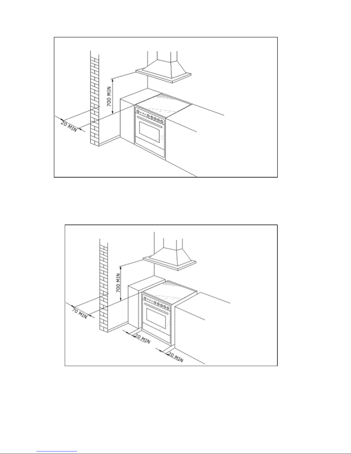
Special attention must be focused on the prescriptions described below regarding room
aeration and ventilation. Any hanging cabinets installed above the work surface must be located at
a distance of no less than 700 mm. (Fig. 1)
Any walls of the adjacent furniture pieces and the wall behind the cooker must be made with heatresistant material that can withstand a minimum temperature of over 75’C.
WARNING: During use the appliance becomes hot. Care should be taken to avoid touching
heating elements inside the oven.
WARNING: Where this appliance is installed in a Marine craft or in Caravans, it shall
NOT be
used as a space heater.
WARNING: In order to prevent accidental tipping of the appliance, for example by a child
climbing on to the oven door, the stabilizing means must be installed according to these
instructions.
WARNING: DO NOT MODIFY THIS APPLIANCE.
WARNING: The appliance is not intended for use by persons (including children) with reduced
physical, sensory or mental capabilities, or lack of experience and knowledge, unless they
have been given supervision or instru ction concerning use of the appliance by a respons ible
person for their safety.
Page 7
7
FIG. 1
FIG. 2
Page 8
8
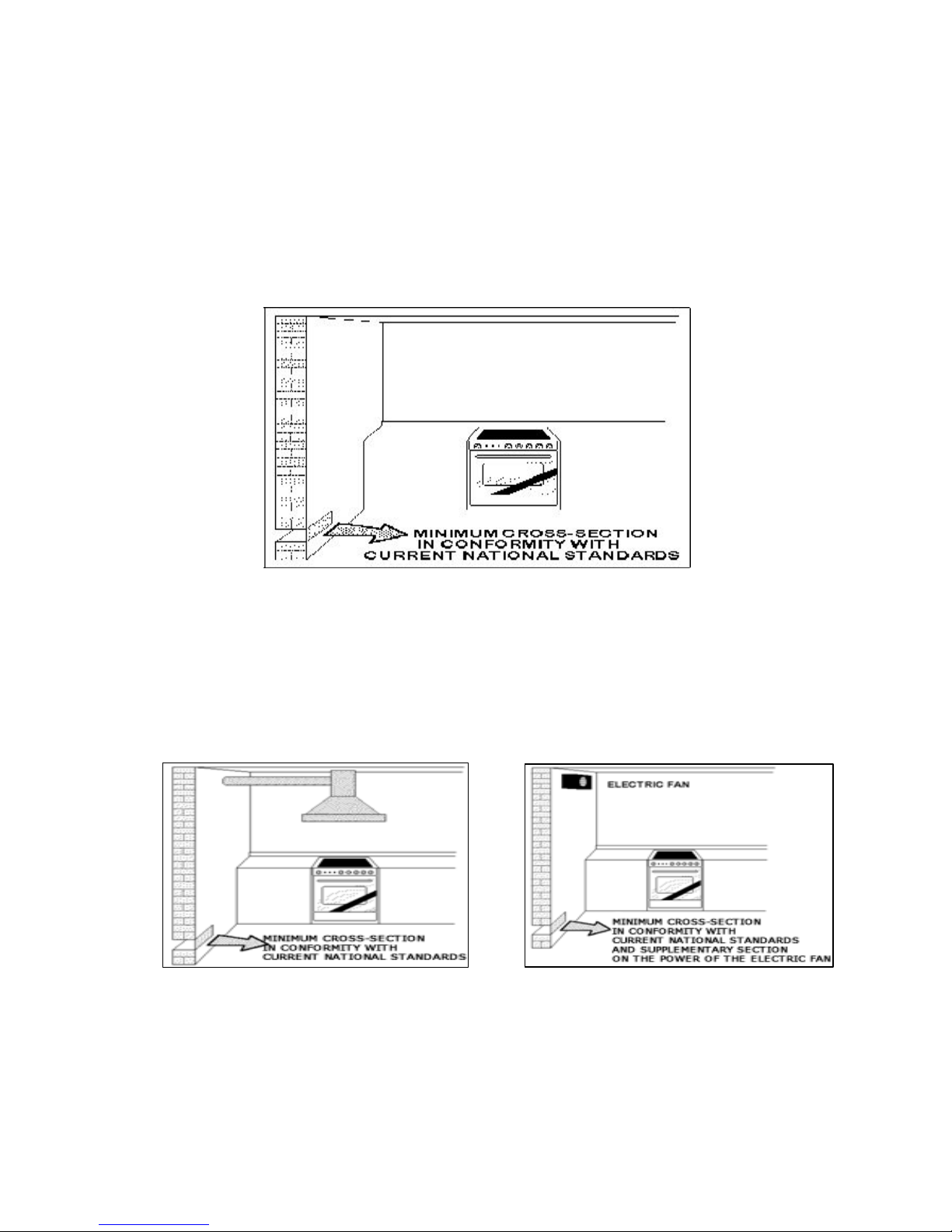
ROOM VENTILATION
To ensure that the appliance operates correctly, the room where it is installed must be continuously
ventilated. The room volume should not be less than 25m³ and the q uantity of air needed should be
based on the regular combustion of gas and on the ventilation of the room. Natural air will flow
through permanent openings in the walls of the room to be ventilated. These openings will be
connected with the outside environment and should have a minimum c ross-section defined by the
current national standards regarding room ventilation (Fig. 3).
These openings should be built so that they cannot be clogged.
Indirect ventilation is also permitted by taking air from the rooms adjacent to the one to be ventilated.
Fig. 3
LOCATION AND AERATION
Gas cooking appliances must always evacuate the combustion products by means of hoods
connected to chimneys, flues or directly outside (Fig. 4). If a hood cannot be installed, it is possible
to use a fan installed on a window or directly facing outdoors, to be operated together with the
appliance (Fig. 5), provided that there is strict compliance with the ventilation regulations.
Fig. 4 Fig. 5
Page 9
9
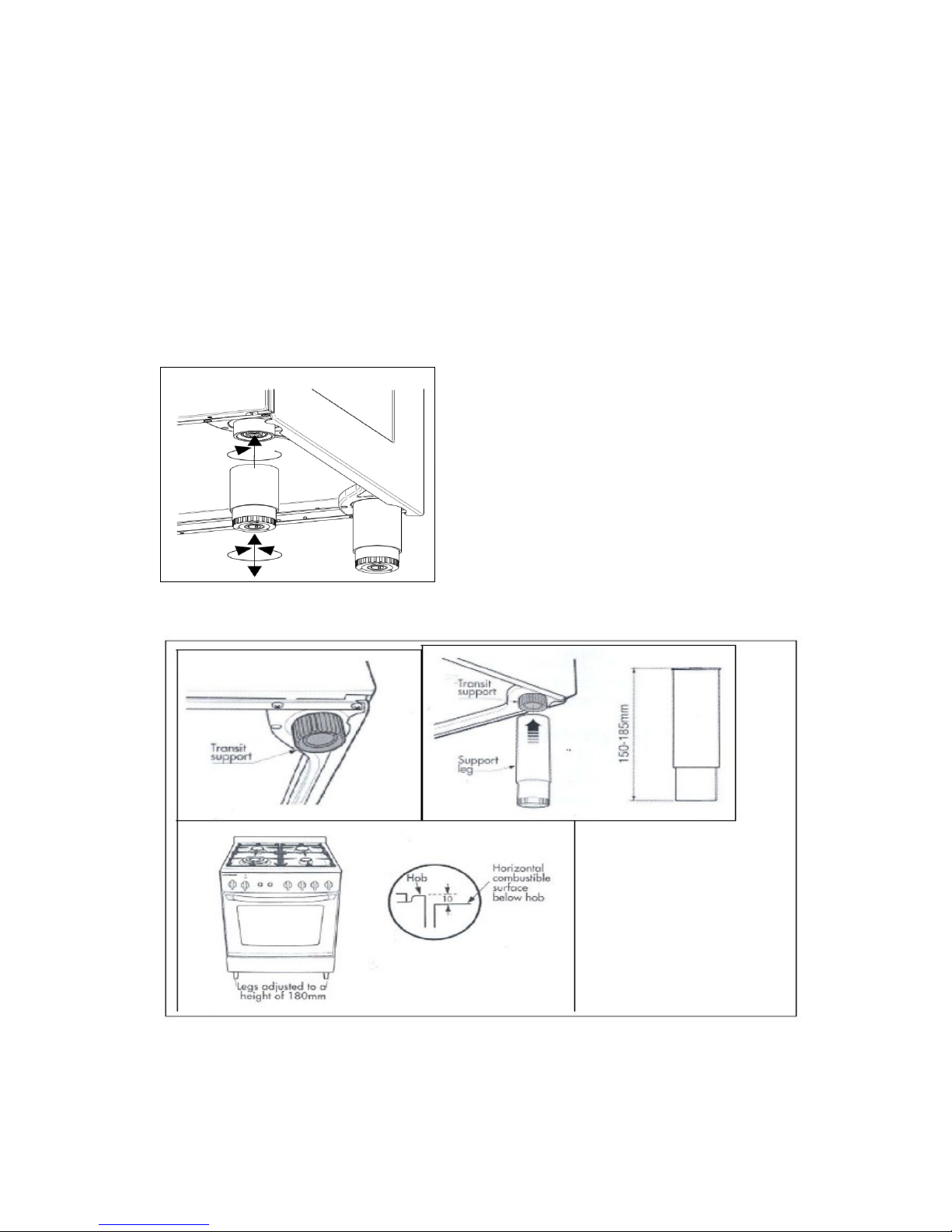
HEIGHT ADJUSTABLE LEGS
Legs are packed in the top box.
Legs should be installed with the appliance being near the location of final installation, they are not
secure for long transport. After unpacking the range, raise it about a foot to insert the legs in their
bases assembled on the lower part of the cooker and lower the range gently to keep any undue strain
from legs and mounting hardware. It is recommended to use a pallet or lift jack instead of tilting the
unit. Tilting the unit of dragging may easily break the legs.
If the legs are not used and the cooker is mounted onto a plinth, fit transit legs to allow for clearance.
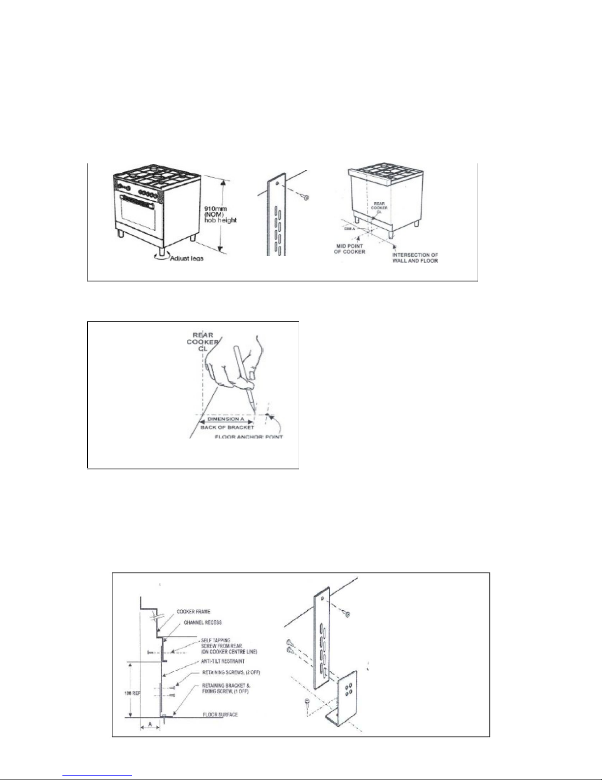
Once legs are adjusted to a nominal cooker height of 910 mm, fit the anti-tilt restraint
bracket.
Page 10
10
ANTI - TILT SYSTEM
The appliance must be installed using the anti-tipping system provided.
1. Fit flat strap to rear of cooker at the
center point
on l
ower
edge using
supplied
screws.
2.
Mark
center
position of the cooker installed
position
on fl
oor.
I
NTERSEC
TION OF
WALL F'LOOR
3.
Measure from rear most
point
hob to mount
point
of
strap. (Dimension A), then using
Dimension A mark back edge of the bracket on center line. Use bracket to mark
fixing
poin
t.
Page 11
11
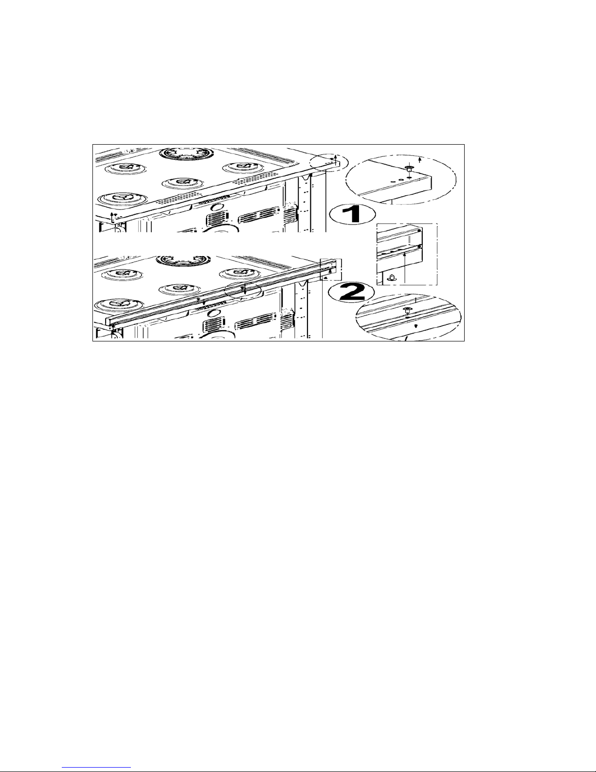
BACKGUARD INSTALLATION INSTRUCTION
Remove the 2 screws that secure the work plan at the rear as shown in below drawing. Arrange the
backsplash and secure it to the bottom side with two screws removed. Further secure the Central
upstand with the screws supplied with the kit.
Page 12
12
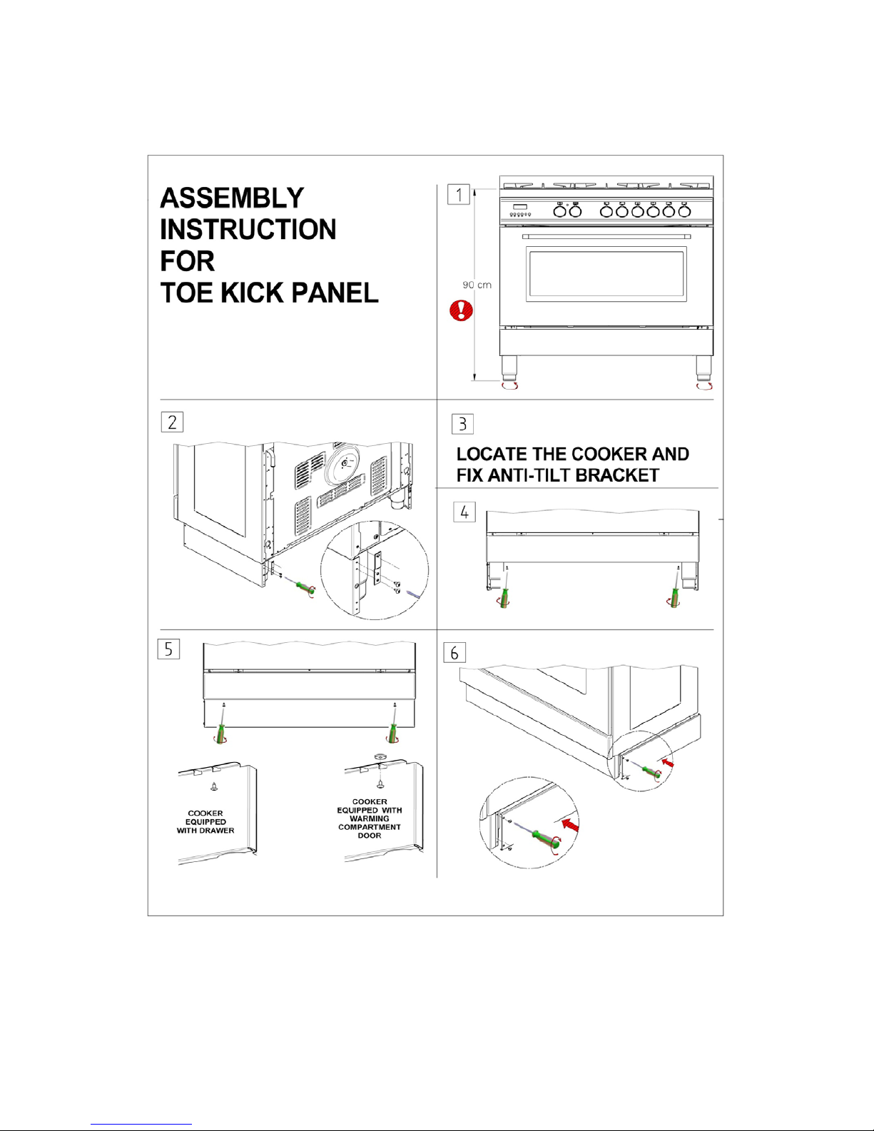
KICK PLATE INSTALLATION
Page 13

13
APPLIANCE ELECTRIC CONNECTION
WARNING: The electric connection must comply with the current legal standards and
regulations.
Before making the connection, check that:
- T he system electric al rating and the current out lets are adequat e for the m aximum power outp ut of
the appliance (see the label applied to the bottom of the casing).
- T he outlet or the system is equipped with an efficient ground connection in accordance with the
current legal standards and regulat ions. The com pany will not be r esponsible for the non-compliance
with these instructions.
When the connection to the power supply network is made using an outlet:
- If the power cord is supplied without a plug, apply a standard plug that is suitable for the load
indicated on the label. Connect the wires according to the diagram shown in FIG.6 and check that:
Letter L (phase) = brown wire;
Letter N (neutral) = blue wire;
Ground symbol
= green-yellow wire;
Fig6.
- The power cord must be positioned so that temperature of 75’ C will not be reached at any point.
- Do not use reductions, adapters or splitters as they might cause false contacts and lead to
dangerous overheating.
When the connection is made directly to the electric network:
- Use a device that ensures disconnection from the mains in which the contacts are opened to a
distance that permits complete disconnection according to the conditions for over-voltage category III.
- Remember that the ground wire must not be interrupted by the circuit-breaker.
- As an altern ative, the el ectric connection c an also b e protect ed by a high-sensitivity residual cur rent
circuit-breaker.
- It is highly recommended to attach the special green-yellow ground wire to an efficient ground
system.
WARNING: If the power cord is replaced, the ground wire (yellow-green) connected to the
terminal, should be longer than the o th er wires by about 2 cm.
WARNING: the power cord must at all times be replaced by qualified personnel.
Page 14

14
TABLE NO. 1: TYPES OF POWER CORDS
Work
surface
Oper
at-
ion
Ove
n
oper
a-
Cross section
230V ~
230V 3~
400V 2N~
400V 3N~
Only gas burner
Gas oven / Gas grill
3 x 0.75mm²
- - -
Gas oven / Electric grill
3 x 1mm²
- - -
Electric Oven
3 x1mm² (MH)
3x1,5mm² (MX M9)
- - -
Ventilated Electric Oven
3 x 1,5mm²
- - -
Gas burner
+ 1 hot
plate
Gas oven / Gas grill
3 x 1mm²
- - -
Gas oven / Electric grill
3 x1,5mm² (MH)
3x2,5mm² (MX /M9)
- - -
Electric Oven
3x1,5mm² (MH)
3x2,5mm² (MX /M9)
- - -
Ventilated Electric Oven
3x2,5mm²
- - -
Gas burner + 2 hot
plate
Electric Oven
3x2,5mm²
4x1,5mm²
4x1,5mm²
5x1,5mm²
Ventilated Electric Oven
3x2,5mm²
4x1,5mm²
4x1,5mm²
5x1,5mm²
4 hot plate
Electric Oven
3x2,5mm²
4x1,5mm²
4x1,5mm²
5x1,5mm²
Ventilated Electric Oven
3x2,5mm²
4x1,5mm²
4x1,5mm²
5x1,5mm²
Ceran
Electric Oven
3x2,5mm²
4x1,5mm²
4x1,5mm²
5x1,5mm²
Ventilated Electric Oven
3x4mm²
4x1,5mm²
4x1,5mm²
5x1,5mm²
THREE-PHASE ELECTRIC CONNECTION
The cookers that can also be connected to three-phase systems normally are factory built for the
single-phase 230V connection and are supplied with a power cord. Based on the connection system
used, install the power cord type indicated in table No.1.
To use the selected connection system change the jumpers on the terminal strip as indicated in the
diagram below. (Fig.7)
Fig. 7
ATTENTION: Th is appliance is not intended to be operated by means of external timer or
separate remote control system.
Page 15

15
APPLIANCE MAINTENANCE
ATTENTION: IMPORTANT WARNINGS
• For cookers resting on a base
ATTENTION: If the cooker rests on a base, take the measures necessary to prevent
the cooker from sliding along the support base.
• For cookers with electric ovens
ATTENTION: The unit becomes hot during use. Do not touch the heating elements
inside the oven.
• For cookers with electric ovens
ATTENTION: The accessible parts can become hot during use. Keep children away
from the appliance.
• For the food warmer compartment (or drop leaf in our case)
ATTENTION: The internal parts of the food warmer can become hot during use.
• For glass doors
ATTENTION: Do not use harsh abrasive cleaning products or metal spatulas with
sharp edges to clean the oven door’s glass since this could scratch the surface and the
glass could break.
WARNING: Do not use steam cleaners to clean the appliance.
WARNING: DO NOT MODIFY THIS APPLIANCE
WARNING - Accessible parts will become hot when in use. To avoid burns young children
should be kept away.
WARNING: If the surface is cracked, switch off the appliance to avoid the possibil ity of an
electric shock
Page 16

16
REPLACING PARTS
Before performing any m aintenance operations, disconnect the appliance from the electricity
network.
To replace parts such as knobs and burners, just remove them from the seats without
disassembling any part of the cooker.
To replace the oven bulb, just uns crew the protectio n cap that pr ojects out inside
the oven. (Fig.8)
Fig. 8
WARNING: Before replacing the bulb, disconnect the appliance from the electric
power supply.
WARNING: The power cord supplied with the appliance is connected to the appliance with an
X type connection (in compliance with standards AS/NZS 60335-1, AS/NZS 60335-2-6 and
subsequent amendments) for which it can be inst alled without the use of special tools, with
the same type of cord as the one installed.
If the power cord becomes worn or damaged, replace it based on the
information reported in table 1.
WARNING: If the power cord is replaced, the installer shall ensure that the ground cable is
longer than the phase cables and also should comply with the warnings regarding the electric
connection.
Page 17

17
USE AND MAINTENANCE INFORMATION
USING THE INDUCTION HOB
HOB CONTROL KNOB
On the control panel, small symbols show the function of each knob or key. Here as follows are the
several controls that a cooker can have:
These symbols show the disposit ion of induction zone on the worktop, the f ull dot identifies the zone
in object (in this case the front left zone).
This symbol shows the running of the oven (9 positions switch).
This symbol shows the electric thermostat for electric oven .
Page 18

18
There are 5 cooking zone and there is a knob that applies and works each individual zone. These
knobs provide control of the ceramic hob's cooking zones. These knobs look similar to the above
image.
The zone it controls is shown above each knob. Turn the knob to the right to set the zone's operating
power; the settings range from a minimum of 1 to a maximum of 9. See above drawing.
The working power is shown by a display on the hob.
Heating accelerator - A
Each cooking zone is equipped with a heating accelerator.
This system allows the zone to be operated at peak power for a time proportional to the heating
power selected.
To start the heating acceler ator, turn the knob to the left, select setting " A" and then release. The
letter "A" will appear on the display on the hob.
You now have 3 sec on ds to select the heating s ett in g of your c hoic e . Onc e a s e tti ng b et w een 1 an d 9
has been selected, "A" and the chosen setting will flash in alternation on the display. '
While the heating accelerat or is in oper ation, the h eating leve l can be incr eased at an y time. T he "full
power" time will be m odified accordingly. If the power is reduced b y turning the knob antic lockwise,
option "A" is automatic ally deactiva ted.
Power Function - P
The power function all o ws t he us er t o operate each heating zon e continuously at the max im um power
for a time of no more than 10 minutes. This function can be used, for example, to bring a large
amount of water to the boil in a hurry, or to turn up the heat under meat.
Turn the knob clockwise and set heating le vel 9, t he n use the knob to set t he "P" position and re le ase
it. "P" appears on the corresponding zone display.
After 10 minutes, the po wer is reduced automatically, the knob retur ns to the 9 setting and the "P"
disappears.
However, the power function can be turned off at any time by reducing the heating level. .
When the power function is selected for one heating zone (e.g. the left front zone), the power
absorbed by the second zone ( Left rear zone) might be reduced to s upply the maximum available
energy to the first zone.
Consequently, the power function takes priority over the heating accelerator.
If a pan is removed from the cooking zone while the power function is on, the function is switched off.
Page 19

19
INDUCTION HOB - ZONES DESCRIPTION
ATTENTION: Metal items such as cutlery or lids must never be placed on the surface of the
hob since they may become hot.
Cooking zones (See image Fig 9)
The appliance is equipped with 5 cooking zones having different diameters and powers. Their
positions are clearl y marked by rings, while the heati ng power is on ly releas ed in the area s hown on
the ceramic hob. The 5 cooking zones are of HIGH -LlGHT type a nd start to hea t up a few seconds
after they are switche d on. The heat level of each zone can be regulat ed from the minimum to the
maximum setting using the knobs on the front panel.
Fig 9
Underneath each cooking zone there is a coil called an inductor, supplied with power by an
electronic system, which generates a variable magnetic field. When a pan is placed inside this
magnetic field, the high frequency currents concentrate directly on the bottom of the pan and
produce the heat needed to cook the foods.
The 5 lights on the cooking zones come on when t he temperature of one or more cooking zones
exceeds 60°C. T he lights go out when the temperature drops to b elow about 60°C. This is a very
good safety feature.
Page 20

20
Zone number,
location and
size:
Power absorption
Normal operation:
With boost power
function:
1 – left front
zone(200mm)
1100W
1400W
2 – right front
zone(200mm)
1100W
1400W
3 – left rear
zone(160mm)
1400W
2000W
4 – centre
zone( 250mm)
2300W
3000W
5 – right rear
zone(250mm)
2300W
3000W
Total power absorption for induction hob 7400W
Table 2
WARNING: When the hob is used for the first time, it should be heated to its maximum
temperature for long enough to burn off any oily residues left by the manufacturing process,
which might contaminate foods with unpleasant smells.
Page 21

21
TYPES OF PANS
This type of appliance can only operate with pans of special kinds.
The bottom of the pan must be iron or steel/iron to generate the magnetic field necessary for the
heating process.
Vessels made from the following materials are not suitable:
• glass;
• porcelain;
• pottery;
• Steel, aluminium or copper without magnetic bottom.
To check that a pan is suitable, simply place a magnet close to its bottom: if the magnet is attracted,
the pan is suitable for induction cooking. If no magnet is to hand, put a little water in the pan, place it
on a cooking zone and switch it on. If the symbol appears on the display instead of the power, the pan
is not suitable.
The pans used for cooking must have certain minimum diameters to ensure satisfactory operation.
Pans larger than the c ook in g zones can also be used, but it is important to ensure that the bott om of
the pan does not touch other cook ing zones, and that it is alwa ys centred over the perimeter of the
cooking zone. (fig.10-11).
Fig.10
Page 22

22
Fig.11
Use only vessels special ly designed for induction c ooking, with thick, completely flat bottom ; if these
are not available, the pans used must not have crowned (concave or convex) bottom. (fig.12)
Fig 12
Pan present device
Each cooking zone is equipped with a "pan present" device, which ensures that cooking cannot start
unless a suitable pan is present on the cooking zone and properly positioned.
If the user attempts to switc h on the cooking zone w ith the pan not positio ned properly or with a pan
which is not of suitable material, a few seconds after the zone is switched on the symbol will
appear to warn the user that an error has been made.
Residual heat
Each cooking zone is equ ipped wit h a device which war ns of res idual heat. Aft er any cook ing zone is
switched off, a symbol ‘H’ may appear on the displa y. This warns that the cook ing zone concerned is
still very hot. Cooking can be restarted while the ‘H’ symbol is turned on.
Page 23

23
SAFETY LOCK
When not in use, the hob can be "Iocked out" to prevent children from accidentally switching it on.
With the cooking zones off, turn the knobs of zones 2 and 4 to the left simultaneously until 5 Ls
appear on the power display and then release the knobs.
To deactivate it, repeat the same procedure: the cooking zone displays will all show 0, indicating that
the cooking zone lock-out function has been deactivated.
Attention: Take care not to spill sugar or sweet mixtures onto the hob during cooking, or to place
materials or substanc es which m ight m elt (plastic or aluminum foil) on it; if th is should oc cur, t o avoid
damage to the surface, turn the heating off immediate ly and clean with th e scraper s upplied while the
cooking zone is still warm. If the ceram ic hob is not cleaned immediately, residues m ay form which
cannot be removed once the hob has cooled.
IMPORTANT
Keep a close eye on children becaus e they are un likely to see the residual heat warming lights. The
cooking zones are still very hot for s ome time after use, even if the y are switched of f. Make sure that
children never touch them.
WARNING: Under no circumstance use aluminium foil or plastic containers to hold the food while
cooking on a glass-ceramic hob.
WARNING: Do not touch the cooking area as long as the light indicating residual heat on the glass-
ceramic hob, is “on”; this indicates that the temperature in the relative area is still high.
WARNING: Never place pan with bottoms which are not perfectly flat and smooth on the hob
WARNING: If you notice a crack in the ceramic hob, disconnect the appliance from the electricity
supply and contact a service person.
WARNING: Your glass-ceramic hob is thermal shock resistant and resistant to both heat and cold.
If you drop a heavy pot on your hob it will not break.
On the contrary, if a h ard object, such as the s alt shaker or the spic e bottle strikes the edge or the
corner of the hob, the hob may break.
WARNING: never use the glass-ceramic hob as support surface.
Page 24

24
USING THE ELECTRIC THERMOSTAT
The thermostat supplied with the relative m odels main tains a constan t temper ature inside the oven a t
a specific temperature setting ranging from 50°C to 250°C. (fig.13)
Fig 13
Turn the knob clockwise and align the selected temperature indicated on the ring with the index
etched on the control panel. Thermostat operat ion is indicated by an ora nge light which will turn of f
when the temperature i nside the oven is 10°C great er than the temper ature setting, and will turn on
when the oven is 10°C less than the temperature setting. The thermostat can control the oven
elements only if the r elative switch is in one of the possible oven element operating modes: if the
switch is in position 0, the thermostat has not effect on the oven elements, which remain off.
Page 25

25
USING THE OVEN FUNCTION KNOB
Please note that the below images may be different to what is supplied on your freestanding
cooker model. However the explanation on how it f unc tions is c orrec t.
This oven has 11 functions as you will see explained below.
There are 4 levels in this oven as per the belo w diagram. (Fig. 14)
Fig. 14
Also there are 2 partially extendable telescopic runner s in this model whereby they can be easily
glided out for safe use. These extendable racks are not evident in the above picture. Please s ee
your cooker.
The knob on the cooker has 9 f unc tions on it as you can see below (Fig.15). The ‘9 switch’ installed in
the multifunction oven m odels is used, along with the thermostat, to c ontrol the electric fan and the
oven elements since the y can be turned on by turning the ‘9 switch’ k nob and the thermostat knob.
Turning just one of the two k nobs will not have any effect on t he oven exc ept to t urn on the o ven light
or the electric fan when inserted. The electric oven is heated b y 4 elements: one on the bottom , two
on the top, one circular; tur ning the switch k nob turns on the elem ent relative to the s ymbol indicated
on the ring but to be activated the therm ostat knob must be turned until the orange light turns on
indicating that the e lement has be en turned on. Placing the s witch knob on any of the nine operati ng
modes turns on the oven light, together with the relative element. Once the temperature and the
elements to be used have been set, the oven elements are turned on and off by the thermostat;
therefore, it is normal for the orange light to turn on and off while the oven is working.
To turn off the electric oven set the switch knob to position 0 to prevent the thermostat from controlling
the elements. Setting t he thermostat knob to positio n 0 turns off the elements b ut it is still possible,
using the switch, to turn on the electric fan and the oven light.
Fig. 15
Page 26

26
The switch has 9 different fixed positions corresponding to 9 different types of oven operation:
- the symbol indicates that all the elements and fan have been turned on (pre-heating);
- the symbol indicates the top and bottom elements have been turned on( traditional);
- the symbol indicates that only the bottom element has been turned on;
- the symbol indicates that only the top el ement have been turned on;
- the symbol indicates that only the grill element has been turned on;
- the symbol indica tes that the top external element, the grill element and the electric fan
have been turned on ( fan grill);
- the s ymbol indicates that the top and bottom elements and the electric fan have been
turned on(fan assisted);
- the symbol indicat es that the circular element an d the electric fan ha ve been turned on(
fan forced/convection);
- the symbol indic ates that the bottom element, the circular element and the electric fan
have been turned on (pizza function/ fan forced with bottom e lement)
When the knob is set to on e of these nine positions , the oven light is al ways on, thus indicating th at
the oven is being energised.
There are also 2 other functions present in these models which do not have an icon but which can be
activated as follows:
• Oven Light only: choose a function with the knob, without activating the thermostat.
• Defrost: choose the ‘convection’ function with the knob, without activating the thermostat.
USING THE PRE HEATIN G FUNCTION
Pre heating function allow one to reach the preset oven temperature as quickly as possible.
Once it reaches the set temperature, the orange light will go out, select the type of cooking through
the switch functions and place the food in to cook.
Note: the preheating function should no t b e used for cooking but just to preheat the oven.
Page 27

27
USING THE PIZZA FUNCTION (FAN FORCED WITH BOTTOM ELEMENT)
When using the oven for the first time it should be operated for a maximum of 30 minutes at a
temperature of about 250°C to eliminate any odours generated by the internal insulation.
Before you start cooking, preheat the oven. After preheating, set the Pizza function, this function
ensures homogeneous cooking. Ideal not only for pizzas but also for biscuits and cakes
For cooking the pizza it is recommended that you set the thermostat at the maximum and place the
baking tray or the grid in levels 3 or 4.
USING THE TRADITIONAL ELEMENT (TOP AND BOTOM ELEMENT)
When using the oven for the first time it should be operated for a maximum of 30 minutes at a
temperature of about 250°C to eliminate any odours generated by the internal insulation. During
normal oven use, select the desired cooking temperature using the thermostat knob and wait until the
orange light turns off before putting in any food. The oven is equipped with 4 guides at different
heights which can be use d to insert shelves or the tray. To keep the oven as clean as possible it is
recommended to cook meat on the tray or on the shelf that has been inserted inside the tray. Table
No. 3 below lists the cooking times and the position of the tray for different types of foods. Personal
experience will he lp to determine any variations in the values reported in the table. In any case, the
below table is only a guideline to assist you with your cooking.
Page 28

28
TABLE NO. 3: TRADITIONAL FUNCTION - COOKING TABLE
TEMP
°C
HEIGHT
MINUTES
MEAT
PORK ROAST
225
4/5
60-80
BEEF ROAST (YOUNG STEER)
225
4/5
60-80
BEEF ROAST
250
4/5
50-60
VEAL ROAST
225
4/5
60-80
LAMB ROAST
225 4 40-50
ROAST BEEF
230
4/5
50-60
ROAST HARE
250
4/5
40-50
ROAST RABBIT
250 4 60-80
ROAST TURKEY
250 4 50-60
ROAST GOOSE
225 4 60-70
ROAST DUCK
250
4/5
45-60
ROAST CHICKEN
250
4/5
40-45
FISH
200-225
3
15-25
PASTRY
FRUIT PIE
225 3 35-40
TEA CAKE
175-200
3
50-55
BRIOCHES
175-200
3
25-30
SPONGE CAKE
220-250
3
20-30
RING CAKE
180-200
3
30-40
SWEET PUFF PASTRIES
200-220
3
15-20
RAISIN LOAF
250 3 25-35
STRUDEL
180 3 20-30
SAVOIA COOKIES
180-200
3
40-50
APPLE FRITTERS
200-220
3
15-20
SAZOIARDI SANDWICH
200-220
3
20-30
TOAST SANDWICH
250 4 5
BREAD
220 4 30
PIZZA
220 3 20
Page 29

29
USING THE FAN ASSISTED FUNCTION
When using the oven for the first time it should be operated for a maximum of 30 minutes at a
temperature of about 250°C to eliminate any odours generated by the internal insulation.
Before cooking, allo w the oven to reach t he des ired te m peratur e setting wai ting f or the ora nge li ght to
turn off. This type of oven is equi pped with a fan that creates forced-air circulation in the horizontal
direction so that the heat g enerated by the top and bottom elements is uniform ly distributed. Thanks
to this type of operation, the ove n can be us ed f or different t ypes of c ook ing at the same t ime, witho ut
changing the taste of each food.
Hot-air circulation guara ntees a uniform distribution of heat. Pr e-heating the oven is not necessar y,
but for very delicate pastries, it is recommended to heat the oven before inserting the trays.
The system partiall y changes the various not ions about tradition al cooking. Meat no longer needs to
be turned while it is cooking and the rotisserie is no longer needed to cook a roast on the spit. Just put
the meat directly on the shelf.
Page 30

30
TABLE NO. 4
Please note that ‘Mar’ in the below table refers to the shelf level in the oven.
Page 31

31
USING THE FAN FORCED FUNCTION
When using the oven for the first time it should be operated for a maximum of 30 minutes at a
temperature of about 250°C to eliminate any odours generated by the internal insulation.
Before cooking, allo w the oven to reach t he des ired te m peratur e setting wai ting f or the ora nge li ght to
turn off. This type of oven is equipped with a circular element around which a fan has been installed
that creates forced-air circulation in the hor izontal direction. T hanks to this type of operation, the fan
forced oven can be us ed fo r diff erent t ypes of cook ing at the s am e tim e, without chang ing the t aste of
each food. Hot-air circ ulation guarantees a uniform distribution of heat. Pre-heating the oven is not
necessary, but for very delicate pastries, it is recommended to heat the oven before inserting the
trays.
The fan for ced system partiall y changes the var ious notions about tradit ional cook ing. Meat no lo nger
needs to be turned while it is cook ing and the rotisserie is no longer neede d to cook a roast on the
spit. Just put the meat directly on the shelf.
Page 32

32
TABLE NO. 5
Page 33

33
USING THE GRILL FUNCTION
The grill is controlled using the oven’s t emperature k nob and set switch knob t o the relative pos ition.
The electric grill can be used for grilling on the oven’s grill.
The static electric grill must be used with the door closed. The tem perature set on the thermostat
(when present) must not exceed 150°C.
Grilling on the shelf: In this c ase, the shelf supplied is placed on level 1 or 2 and the f oods to be
grilled are placed on top, whi le the tray is inserted on the lower levels to col lect the cooking juices.
Then turn on the grill element switching the thermostat to the relative position (electric oven version).
WARNING: the accessible parts may become very hot while grilling. Keep children away from
the appliance while cooking.
USING THE FAN GRILL FUNCTION
The fan ass isted electric grill is a special function eq uipped only on the multifunction oven. Set th e
function knob switch to the relat ive pos it ion t o act ivate the gr i ll element and the electric fan. Generall y,
to ensure excellent grilli ng, place the oven she lf in the middle position while the oven tray shou ld be
inserted at the bottom.
IMPORTANT: When using the grill, set the thermostat knob no higher than 175 °C, which is
between the 150 °C and 200 °C setting, to avoid overheating the front of the appliance. In fact,
fan assisted grilling must be carried out with the door closed.
COOLING FAN OPERATION
The cooker is equipped with the cooling fan that star ts operation eac h time a specific tem perature of
cooker was reached and will stop when the temperature decreases. The fan circulates the air
between the control panel and the oven door and also allows the control panel and the oven door stay
at a warm temperature during the appliance operation in any condition.
USING THE MINUTE-MINDER
The minute-minder advises the user, with an acoustic signal, when food has been cooked, after a
certain time period has elapsed. To use the device, wind the minute-minder by turning the knob
clockwise one complete tur n. Then turn the knob c ounterclockwise so that the indicator corr esponds
with the selected cooking time.
Page 34

34
3 KEYS - ELECTRONIC PROGRAMMER
The first start up
The numbers and the A letter on the disp lay are blinking when the oven is switche d on for
the first time, or after a power cut: the appliance cannot be operated in this condition.
To set the hour and/or to enable the appliance to operate press the M key for at least 2
seconds: the A letter turns off and the numbers now are steady on the display.
The dot (3) starts blinking: press the - or
+
key to set the hour.
The hour is accepted by the progr ammer just a few seconds after having released the key.
N.B. the appliance can b e correctly used for cook ing only when you will see on the display
the symbol (2).
The symbols on the display:
1
A
*
Automatic programm e is wor kin g.
(* in some models there is the writinq 'Auto' instead of A).
2
The appliance is ready for manual us e (not automatic).
3
•
When blinking, the programmer is in setting hour mode.
4
Timer set.
5
-
Decreasing numbers wh en set tin g the ti mer .
Also for choosing your desired sound level ( 3 levels available).
6
M
"Mode" key to acce ss the progr am mi ng op tio ns of the progr a mm e.
7
+
Increasing numbers when setting the timer.
Timer
The purpose of the time r is a sound signal, which can be set for a m ax time of 23h59min.
once elapsed the set tim e, the (4) symbol turns off an d a sound signal is heard; this sou nd
set off automaticall y in 7min, or you c an stop it by pressin g any key of the pro grammer. To
set the timer press the M key f or 2 seconds, or to see the (4 ) symbol blinki ng. Set the tim er
by using the
+
or - keys. Relea se the + or - key whe n you ha ve mat ched y our des ire d time. I n
a few seconds the current time appears on the display together with the (4) symbol. The
countdown starts immediately from now on.
Semi-autom atic cooking
Cooking time: Once having selected a cooking function and set the desired temperature,
press the M key for a 2 seconds time to access the programming mode. The (4) symbol
appears. Release and press again the M key. O n the display, the A symbol starts blinking
and the " dur " writin g appears on the dis play, then it changes t o O' 00. Set the coo king time
with the - or
+
keys. (max availab le time: 10h) . The selected time is automatically processed
Page 35

35
by the programmer in a few s ec onds, or yo u can als o touch t he M key many ti me s just to see
again the current time.
The A and (2) sy mbols w ill be on th e display. Once t he set coo king time is finished , a sound
will be heard and the ov en automatically switches off. Please see the f ollowing paragraphs
about how to disable the sound alarm and restarting the oven.
End of cooking
Once having selected a cooki ng func tion an d set the d esire d temp eratur e, tou ch the M k ey to
access the program ming mode for at least 2 sec. the (4) symbol switch es on. Release and
touch again the M key.
On the display the A symbol sta rts blinking and the writing "dur" appears. Touc h again the M
key. On the display the writi ng "End" appears. The la st one changes few seco nds after with
the symbol 0· 00.
Set the end of cooking time with the keys - or
+.
(maximum avai lable time: 10hOOm).
The selected time is a utomatically proces sed by the programmer in a fe w seconds, or you
can also touch the M key many times just to see again the current time.
The cooking imm ediately starts, whil e on the program mer display the current time is shown
again in a few seconds.
The A and (2) sym bols will be on the display.
Once the set end of cooking time is finished, a sound will be heard and the oven
automatically switches off. Please see the following paragraphs about how to disable the
sound alarm and restarting the oven.
Automatic cooking
Set a cooking time follo wing the i nstructio ns on the co oking tim e paragra ph, then s et the end
of cooking tim e following the instructions o n the previous paragraph. ( Max available end of
cooking time 10h). The oven automatically switches on at a determined time which is the
difference between the e nd of co oki ng tim e an d th e coo kin g tim e.
During the waiting tim e befor e cookin g, which goes from the ove n start to the h eating, o n the
display appears the A symb ol to show that an aut omatic program is o n and the current time .
The oven on is marked by th e (2) symbol. Once the set en d of cooking time is
finished, a
sound will be heard and the ov en au to mat ic ally sw itch es off .
Please see the following paragraphs about how to disable the alarm and restarting the oven.
How to disable the sound alarm: To disable the sound just touch one of the keys.
Operating again th e
oven
Once a semi-automatic or auto matic cooking has expire d, on the display appear t he current
time and the blinki ng A symbol. In this c ondition, the heatin g elements and the li ght bulb of
the oven are disabled. To enable again the oven, just touch and keep the M key up to see the
symbol (2) on the display and the A sym b ol dis app ear s.
OTHER FUNCTIONS
How to delete a cooking time
(Semi-automatic or Automatic)
To delete a semi-automatic or automatic cooking program, with the A symbol on, touch
together the - and
+
keys for at least 2 seco nds or anywa y up to se e the (2 ) and the d isabli ng
of A symbol.
How to delete the countdown timer
To delete the counting of the timer, which symbol is (4) touch the M key for at least 2
seconds or anyway up to see the (4) symbol blinking. Touch together the - and
+
keys.
Checking the function settings
The set the rem aining time of every c ooking function of the prog rammer can be recall ed to
the display by entering in program mode with the M key. Touch and keep the M key for
almost 2 seconds or any way up to see the (4) symbol. The remaining time appears o n the
display, or a series of z ero numbers if the tim er is disabled. Touch again the M key. On the
display appears the "dur" writing, then alternately the remaining time or a series of zero
number (disable timer).
Page 36

36
By touching again the M key, the end of cooking time ap pears together with the "End" writing.
How to change the current time or the sound level
With the programm er in s tan dar d m od e, t he ( 2) s y mb ol is on, t ou ch t og eth e r the - and + keys
for at least 2 seconds or anyway up to see the do t (3) blinki ng .
To update the hour on the display:
touch the + or - keys.
To change the sound level:
touch the M key. On the display appears the writing:
Ton..followed by a number. Select with the - key your favorite sound level.
Note: number 1 i s refer red to the highest sound level. The available levels are 3.
Attention:
Power cut causes the loss o f any program, even the cl ock; that means the
programmer wil l have to be set agai n.
CLEANING THE APPLIANCE
CATALYTIC SELF - CLEANING LINERS
The self-cleaning oven differs from the standard one in the fact that its internal surfaces are
enamelled with a special microporous material which absorbs and eliminates the greasy particles
during the cooking. In case of spillag e of greasy liquids, the self-cleaning action becomes not efficient;
therefore it will be necessary to clean the oven properly. Proceed in the following way: (a) wipe a
humid sponge on the grease stains; (b) heat up the oven t o the maximum temperature; (c) wait 5
minutes and then s witc h of f the o ven; (d) wait until the ove n g ets coo l a ga in; ( e) wipe again the humid
sponge on all the surface. Do not use detergent in any case.
WARNING: Before cleaning the appliance, it should be disconnected from the power
supply and turn off the main gas feeder valve.
Cleaning the ceramic hob
Before carrying out any operations, disconnect the appliance from the electricity supply.
The ceramic hob must be cleaned regularly, preferably after each use, when the residual heat
warning lights have gone out.
Any marks left by the use of pans with aluminium bottoms can be wiped off with a c loth dipped in
vinegar.
If burnt residues are left af ter cooking, remove them with the scraper provided, rinse with water and
dry thoroughly with a clean cloth. Regular use of the scraper considerably reduces the use of
chemicals for daily cleaning of the hob.
In any case, abrasive or corrosive cleaners (e.g. powder products, oven cleaner sprays, stain
removers and metal scouring pads) must never be used.
Any liquid that overflows from pots must always be removed using a rag.
Cleaning the enamelled parts
To maintain the original features of the enamelled parts they should be cleaned frequently with
soapy water. Never use abrasive powders. Do not leave acidic or alkaline substances on the
enamelled parts (vinegar, lemon juice, salt, tomato sauce, etc.) and do n ot wash the enamelled parts
Page 37

37
while they are still hot.
Cleaning the STAINLESS steel parts
Clean the parts with soapy water and then dry them with a soft cloth. The shine is maintained
by periodically using special products that generally are found in the market. Never use abrasive
powders.
How to remove the door
To thoroughly clean the inside of the oven, it is recommended to disassemble the door by care fully
following the ins tructions described in Fig.1 and 3 below. Insert the hook into the hinged sec tor. Put
the door in a semi-open position and using both hands pull it towards you until it is released from the
attachment. To replace the door, do the opposite making sure to insert the two sectors correctly. In
addition, the side racks can be removed very easily, by loosening the lock rings that attach them to
the oven.
Removing inside glass for cleaning
To remove inside glass door for cleaning follow below fig. 2-3 and 4 and after cleaning the glass
reinstall it operating in the reverse way. Use fig. 4-3 and 2.
Removing the inside glass for cleaning
Page 38

38
Removal of roof tray
The roof tray above the grill element can be removed for cleaning.
- Support the grill element with one hand while removing the wing nuts that hold the element in
in place.
- The element position will drop slightly allowing removal of top liner.
- Once cleaned and dried, the top liner can be placed back into position, above element, and
re-secured with the two wing nuts.
- The liner will only fit into one position so care must be taken to locate it the rear lugs and the
front large lip must be facing downwards.
- Do not use the oven unless the liner is f itted and the element h as been re-secured with the
wing nuts.
Page 39

39
TROUBLE SHOOTING
If you have a problem with your appliance check the following before you ring service.
Pr
oblem
What
to do
Oven or hob
not
working
Check the electricity
is
turned
on
Check your fuses. If the fuse continues to fail please contact service person
Check the circuit
breaker
Ensure correct knob
is
tur
ned
Dry
or clean ignition electrodes
Make sure flame ports and ignition areas are clean and dry
Check gas main is on
Ensure cap/crown correctly fitted.
Replace
or
tighten light globes
Heating up problem s
Oven not pre-heated – Pre-heat oven for 30 minutes
Check oven
door is
closed
properly
Remove
foil or
trays from bottom
of oven
Change set oven
temperature
Preheat your
oven
before you put the
food in to be cooked
Unit smoking/
odours
Turn the
oven on high to
remove protective
oils
Persistent
gas
smell
– do not operate the oven
. Contact service person.
Condensation
Note:
some condensation
is
normal
and is to be
expected during
cooking
Reduce the amount
of
water used
for cooking
Leave the
door open
after cooking
if food
remains
in
cooker
for warming
Oven shelves are tight
Remove oven shelf and re-insert, check correct alignment on runners
Recommended maintenance schedule for this appliance is 24 months
Page 40

40
Affix spare rating plate of the product here or on
easily accessible area or in an adjacent cupboard or similar.
Page 41

41
We appreciate your feedback.
Please review our products on www.
blanco-australia.com
Page 42

42
Page 43

43
 Loading...