

Page 1
MODEL: CGG905WTFFC
We ask that you carefully read the instructions within this booklet to enable you to abtain quality results from the outset.
The appliance must be installed only by an authorised person in compliance with the instructions provided. The manufacturer
declines all responsability for improper installation which may harm persons and animals and damage property.
The appliance must be used for the purpose for which it was expressly designed. Any other use (eg heating rooms) is considered to
be improper and consequently dangerous. The manufacturer declines all responsability for damage resulting from improper and
irresponsible use.
The manufacturer shall not be held responsible for any inaccuracies in this handbook due to printing or transcription errors. The
designs in the figures are purely indicative.
The manufacturer also reserves the right to make any modifications to the products as may be considered necessary, useful or in
the interests of the user, without jeopardizing the main functional and safety features on the products themselves.
If your cooktop requires service, please contact your local customer service centre or your nearest Blanco agent listed at the back of
this booklet.
COD. 04068GGB - 02.02.2011
Dear Customer
Thank you for purchasing a Blanco Cooktop.
Before we continue telling you about this cooktop, we cordially invite you to become part of the Blanco family by
subscribing to ongoing information and invitations. Please visit our website where you can subscribe and request
such things as invitations to future cooking classes and gourmet recipes. Go to www.blanco-australia.com and fill
in the subscription details.
You will find that the clean lines and modern look of your Blanco Cooktop blends perfectly with your kitchen décor.
It is easy to use and performs to a high standard.
Blanco also makes a range of products that will enhance your kitchen such as ovens, rangehoods, dishwashers,
microwaves, sinks and taps.
There are models to complement your new Blanco Cooktop.
Of course we make every effort to ensure that our products meet all your requirements, and our Customer
Relations department is at your disposal, to answer your questions and to listen to all your suggestions (see back
cover of manual).
Please complete the warranty section of this manual and keep your receipt as proof of purchase. Retain all
documents relating to the purchase of this products.
Blanco is committed to providing increasingly efficient products that are easy to use, respect the environment and
are attractive and reliable.
BLANCO
INSTRUCTIONS AND RECOMMENDATIONS
FOR THE USE, INSTALLATION AND
MAINTENANCE OF BUILT-IN GAS
TOUCH CONTROL
Page 2
2
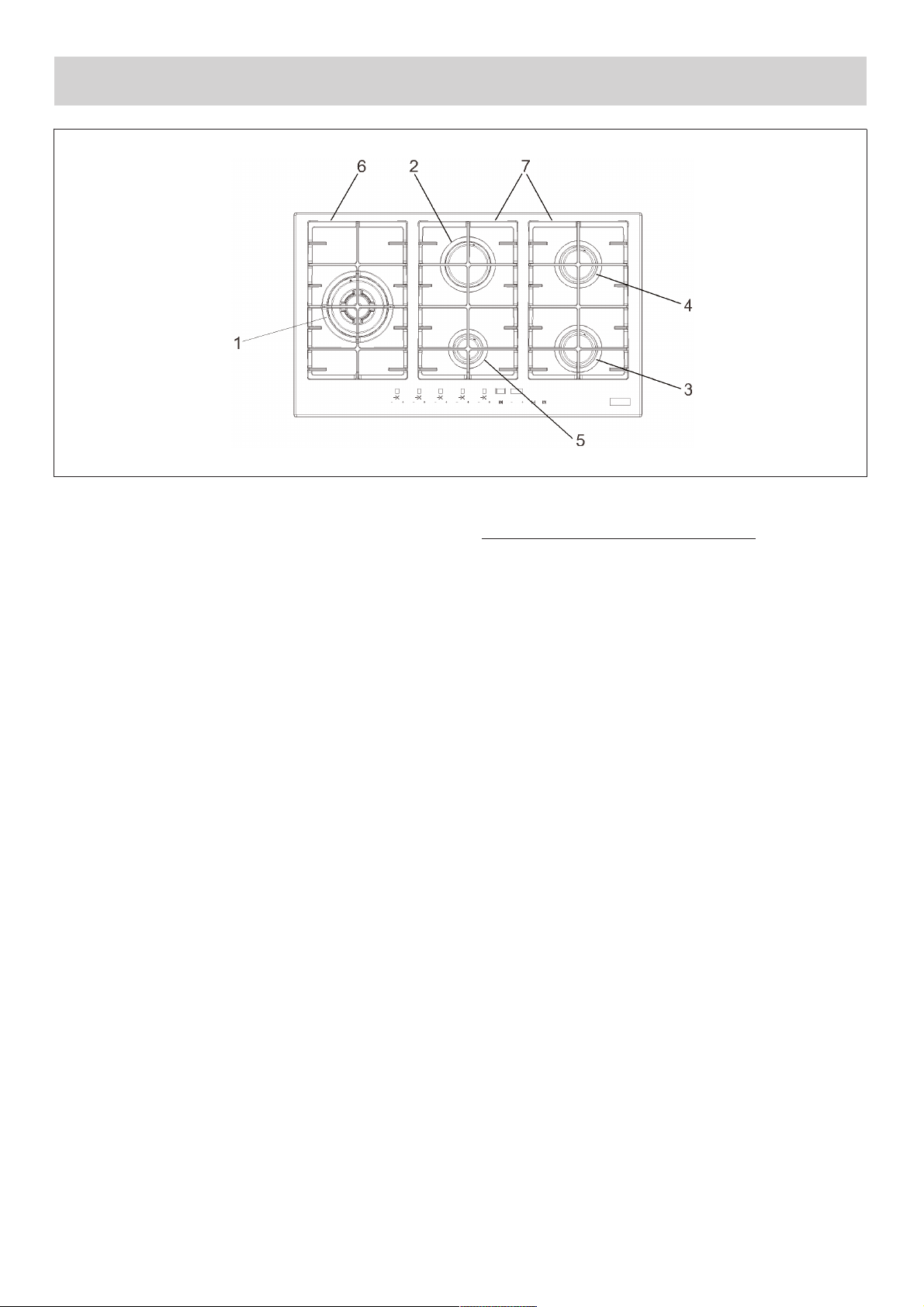
DESCRIPTION OF HOBS
Natural Propane
1 Ultra rapid burner/WOK 15.2 MJ/h 16.2 MJ/h
2 Rapid burner 10.8 MJ/h 10.4 MJ/h
3 Right front semirapid burner reduced 5.4 MJ/h 4.86 MJ/h
4 Right back semirapid burner 7.1 MJ/h 6.3 MJ/h
5 Auxiliary burner 4.1 MJ/h 3.6 MJ/h
6 1F cast iron trivet
7 2F cast iron trivet
This Cooktop is equiped with an electronic burner management system, with touch control panel.
Caution: this appliance has been designed for domestic use in domestic environments by members
of the general public. It must be used by fully aware adults. Children should not be allowed to
approach or play with the appliance. The easy-to-reach front areas of the appliance may become
extremely hot during use.
Supervise children and incapacitated people during use, making sure that they do not touch hot
surfaces and stay away from the appliance during operation.
Do not modify this appliance.
Page 3
3
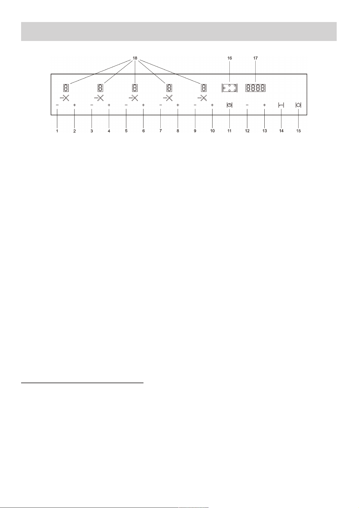
USE
1 - Burner 1 – button
2 - Burner 1 + button
3 - Burner 5 – button
4 - Burner 5 + button
5 - Burner 2 – button
6 - Burner 2 + button
7 - Burner 4 – button
8 - Burner 4 + button
9 - Burner 3 – button
10 - Burner 3 + button
11 - Clock button
12 - Clock programming – button
13 - Clock programming + button
14 - Safety lock button
15 - ON/OFF button
16 - Burner in use position indicator
17 - Timer display
18 - Burner heat settings display (0 - 7)
FUNCTIONS available to the user/fitter:
the main functions of the device are:
● standby mode (burners off, control panel active).
● Control panel lock to protect against accidental lighting/programming.
● Regulation of the capacity of every burner at 7 levels.
● Safety lock with manual reset via release procedure carried out from the control panel.
● Procedure to regulate the capacity to the minimum level for every burner (for fitter only).
● Programming the type of fuel used: methane/lpg (for fitter only).
● Programming of the switch off time for every burner.
● Maximum duration time for each burner pre-programmed into the FLASH memory equates to 4
hours.
● Temperature measured on the electronic card.
● Management of anomalies/faults via code indicated on display.
Page 4
USE
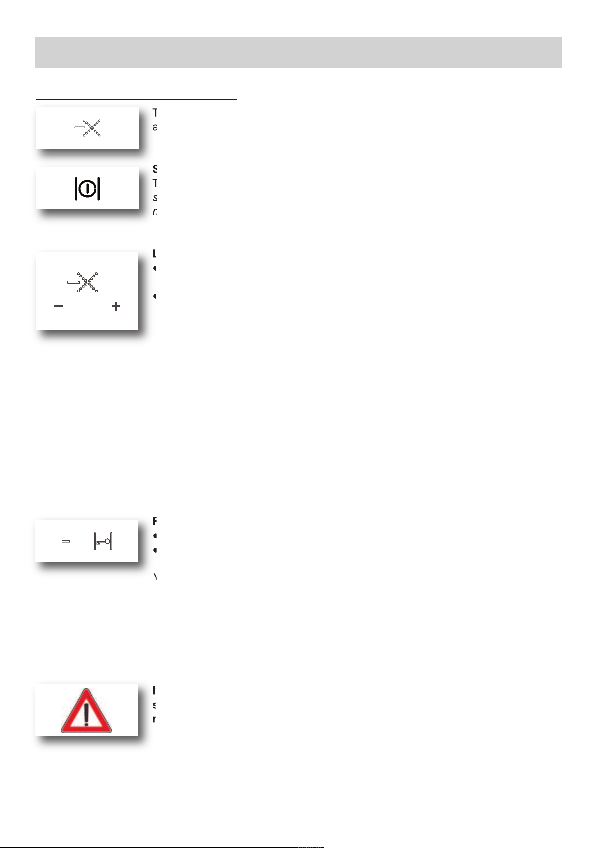
1) IGNITING AND ADJUSTING
4
The burner indicator above each burners touch controls indicates which burner (s)
are in use. The power level for each burner can be set to 7 heat levels.
Switching on
Touch and hold the On/Off button for 2 seconds to switch on the hob. The hob
switches on and the display for each cooking zone will show 0 to indicate that
none of the burners is ignited.
Lighting burners with spark ignition
● Touch the + button of the burner you want to ignite.
‘0’ is blinking for 3 seconds.
● Touch the + button again within 3 seconds to set level 7 or touch the - button
within 3 seconds to set level 5.
The burner ignites and the display shows the level. The display above the timer
button shows the burners that are ignited and that are linked to a timer.
The control system will make three attemps at intervals of 10 seconds to ignite the
burner. Should the burner fail to light, it locks and the corresponding display
shows ‘b’. To use the burner again, you must release the burner.
Setting a burner level
If a burner has ignited, you can set the level with the corresponding + button or button. You can touch the button several times or you can touch and hold the
button until the correct level appears in the display.
Releasing a burner
● Be sure that the hob is switched on.
● Touch simultaneously for at least two seconds the most left handed - button and
the child lock button.
You will hear a short beep; you can release the buttons. The display of the burner
that has to be released shows ‘0’ to indicate that you can ignite the burner again.
When the burner does not ignite, check whether:
● the burner cap is placed on top of the burner correctly;
● the burner/spark plug is clean and dry.
If the release procedure is repeated 5 times in a row during a 15 minute time
span, the device will indicate Flt06 and will accept no further request for
release for another 15 minutes.
Page 5
USE
5
Switching off one burner
Touch the + and the - button of the burner you want to switch off simultaneously
for 2 seconds or use the - button to set the burner to 0.
The burner switches off and above the touch control a blinking ‘H’ appears for
some minutes to indicate that the burner is still hot.
Switching off all burners at the same time
Touch the On/Off button.
The hob is now switched off. If a burner is still hot, a blinking ‘H’ will appear for
some minutes in the display of the corresponding burner.
PROGRAMMABLE TIMER
It’s possible to set a switch-off time for each burner, so the burner switches off
automatically when the set time has passed. You can only set the switch-off time if
the burner is ignited.
●The countdown starts as soon as the programming of the switch-off time for a
burner has been confirmed. If you do not confirm the set time, the countdown will
start after several seconds.
●The set switch-off time for each programmed burner can be seen in the timer
display (after the right burner has been selected).
●If the time has elapsed, the burner switches off and you will hear a beep several
times during 30 seconds.
Programming the burner switch-off time
●Switch on the hob, ignite a burner and set the power.
●Touch the timer button.
An indicator above the timer button will start blinking to indicate the burner that is
currently selected for programming the switch-off time. With the timer button you
can select each burner that has been ignited. In the display ‘t0.00’ appears to
indicate that a time has not been set yet for the selected burner.
●Touch the + button of the timer to set the switch-off time for the selected burner
(increases by 1 minute).
●Touch the timer button again to confirm the setting.
Above the timer button the indicator lights of burners that are linked to a timer
will stay illuminated.
●During programming you can set the time to ‘0.00’ by touching simultanously the
+ button and the - button of the timer.
●You can see the remaining switch-off time for a burner by touching the timer
button again. The time of the burner which indicator light is blinking appears in
the display. If you want to see the remaining switch-off time of another burner,
you have to touch the timer button again to select a different burner.
●You can adjust the time by touching the timer button and selecting the correct
burner with the timer button. With the + button and the - button of the timer you
can adjust the time.
●If you switch off the burner, the programmed switch-off time dissappears.
Page 6
6
USE
CHILD LOCK
Your hob is equipped with a childproof lock that lets you lock the appliance for
cleaning or to prevent unintended switching on by children.
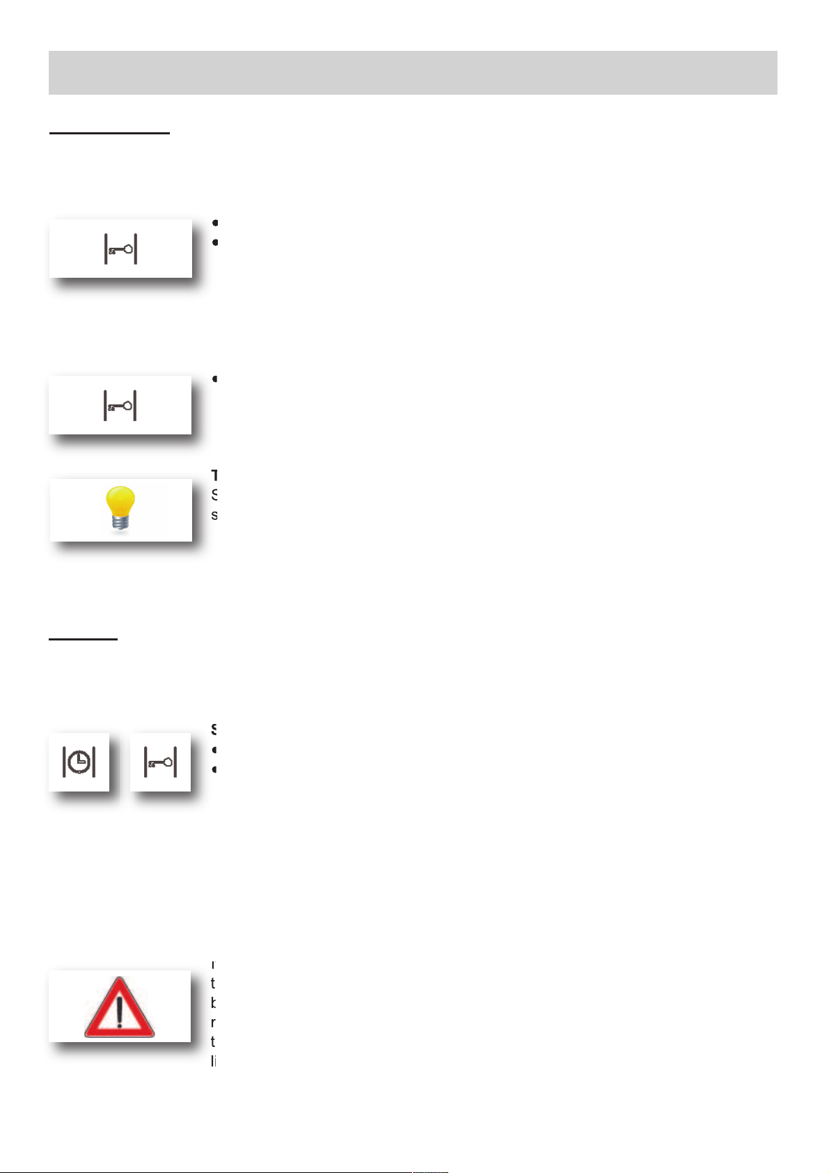
Switching on the child lock
● Be sure that the hob is switched off.
● Touch and hold the child lock button for at least two seconds.
You will hear a single beep and will see a dot in every burner display. The child
lock is now activated.
► It’s not possible to release a burner when the child lock is activated.
First you have to deactivated the child lock.
Switching off the child lock
● Touch and hold the child lock button for at least two seconds.
You will hear a single beep and the dot in every burner display disappears. The
child lock is now deactivated.
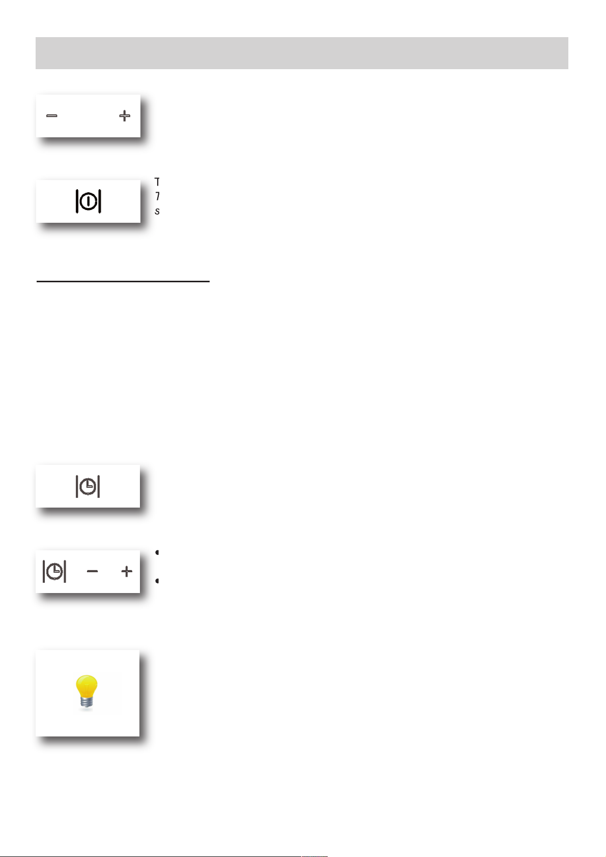
Tip
Switch the hob to child lock mode before cleaning it to prevent it from accidentally
switching on.
CLOCK
You are able to see the present time in the display. You have to set the time
before using the hob for the first time. Also after a power failure you have to set
the time.
Setting the clock
● Be sure that the hob is switch on.
● Touch the timer button and the childlock button simultaneously for at least
3 seconds.
‘0’ in front of the dot is blinking. You can set the hours now.
● Touch the + or the - button of the timer to set the hours.
● Touch the timer button again.
‘00’ behind the dot is blinking. You can set the minutes now.
● Touch the + or the - button of the timer to set the minutes.
● To finish, touch the timer button again to confirm the setting.
Now you will see the present time in the display when you switch on the hob.
If there are burners that are connected to the timer, you cannot see the present
time in the display. The time that is left over of the timer which indicator light is
blinking, is shown in the display. By touching (several times) the timer button (until
no cooking zone is selected any more; no blinking lights), you can see the present
time in the display. After a few seconds the set time of the burner (which indicator
light is blinking) appears in the display again.
Page 7

7
USE
WARNINGS:
- never leave the appliance unattended while the
burners are in use and ensure that children
are kept at a safe distance. Make sure that pan
handles are cor rectly p ositioned and
supervise the cooking of foods in oil and fat,
as these are highly flammable.
- D o n o t u s e spr a y s n e a r the appliance
during use.
- Do not drag pans across the glass hob as this
may scratch the surface.
- Should a crack appear on the surface of the
glass, disconnect the appliance from the
electricity supply immediately.
- Do not use the hob as a work surface.
- Do not place pans with an unstable or deformed
bottom on the burner, as these may tip or spill
their contents, causing accidents.
- The machine must not be used by people
(including children) with impaired mental or
physical capacities, or without experience of
using electrical devices, unless supervised or
instructed by an expert adult responsible for
their care and safety. Children should not be
allowed to play with the equipment.
- This product is not for use in marine craft,
caravans or mobile homes.
- Containers wider than the unit are not
recommended.
- Never use aerosol near the appliance when it
is operating.
- Do not store or use flammable liquids or items
in the vicinity of the hotplate.
Burners
Power ratings
Pan Ø
in cm
Natural Propane
Ultrarapid/ WOK 15.2 MJ/h 16.2 MJ/h
24 ÷ 26
Rapid 10.8 MJ/h 10.4 MJ/h
20 ÷ 22
Semirapid red. 5.4 MJ/h 4.86 MJ/h
16 ÷ 18
Semirapid 7.1 MJ/h 6.3 MJ/h
16 ÷ 18
Auxiliary 4.1 MJ/h 3.6 MJ/h
10 ÷ 14
Page 8
8
USE
Notes:
use of a gas cooking appliance produces heat and moisture in the room in which it is installed. The
room must therefore be well ventilated by keeping natural air vents clear and by activating a
mechanical aeration device (suction hood or electric fan).
Intensive and lengthy use of the appliance may require additional ventilation. This can be achieved
by opening a window or by increasing the power of the mechanical exhausting system if installed.
Abnormal operations:
Any of the following are considered to be anormal operation and may require servicing:
- yellow tipping of the hob burner flame.
- Sooting up of cooking utensils.
- Burners not igniting properly.
- Burners failing to remain alight.
- Burner extinguished by cupboard doors.
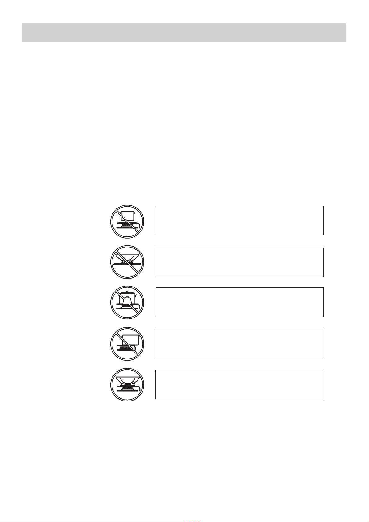
Do not place anything, eg. flame tamer, asbestos
mat , b etwe en pan and pan sup port as serious
damage to the appliance my result.
Do not remove the pan support and enclose the
burner with a wok stand as this will concentrate and
deflect heat onto the hotplate.
Do not use large pots or heavy weights which can
bend the pan support or deflect flame onto the
hotplate.
Symbol 1
Symbol 2
Symbol 3
Locate pan centrally over the burner so that it is
stable and does not overhang the appliance.
Use only a wok support supplied or recommended by
the manufacturer of the appliance.
Symbol 4
Symbol 5
Page 9

9
FIG. 1 FIG. 2
CLEANING
CAUTION:
always disconnect the appliance from the gas
and electricity mains before carrying out any
cleaning operation.
2) WORKTOP
If you wish to maintain the shine of the glass, it is
important to clean the hob every time you use it with
lukewarm soapy water, rinsed and dried.
The enamelled grids, enamelled burner caps “C”,
and burner heads “M” (see fig. 1) must also be
washed and the ignition elements “AC” and flame
sensors “TC” (see fig. 2) must be cleaned. Do not
wash them in the dishwasher.
Cleaning operations must be carried out when the
hob and components are not hot and the use of
metal scou ring pads, p owder abra sives and
corrosive sprays must be avoided.
Do not allow vinegar, coffee, milk, salt water, lemon
juice or tomato juice to remain in prolonged contact
with the surfaces.
WARNINGS:
when reassembling the components, observe
the following recommendations:
- check that the holes in the burner heads “M”
(fig. 1) are not blocked by foreign bodies.
- Ensure that the enamelled covers “C”
(fig. 1) are correctly positioned on the burner
head. The covers are correctly positioned on
the head when they are perfectly stable.
- Do not use steam jets to clean the appliance.
- To prevent difficulties with lighting, regularly
clean the ignition elements (ceramic and
electrode) and flame sensors.
Page 10

10
INSTALLATION
FIG. 3
TECHNICAL INFORMATION FOR THE INSTALLER
This appliance shall be installed only by authorised personnel and in accordance with the manufacturer’s
installation instructions, local gas fitting regulations, municipal codes, electrical wiring regulations, AS 5601 Gas Installation and any other statutory regulations.
Ventilation must be in accordance with AS 5601 - Gas Installation. In general, the appliance should have
adequate ventilation for complete combustion of gas, proper flueing and to maintain temperature of
immediate surroundings within safe limits.
The wall and bench surfaces must be capable of sustaining temperatures of 75 °C.
All laminates, fixing adhesive and surfacing materials should be certified suitable for this temperature.
INDICATIONS FOR INSTALLATION
●The device is designed to remain operational for less than 24 h (non-permanent operating system). When
this limit is reached, a regulation stoppage occurs so the device can check its efficiency.
●This automatic device is a safety device and must not be altered. Interference with this device will eliminate
any responsibility by the manufacturer and invalidate the warranty.
●Observe the national and European standards applicable (e.g., EN 60335-1/EN 50165) in relation to
electrical safety.
●Before entry into operation, check the wiring carefully: incorrect wiring may damage the device and
jeopardise the safety of the system.
●Connect and disconnect the hob only after cutting off the electricity supply.
●Avoid exposing the device to drops of water.
●Avoid laying the valve wires along with the high voltage wires of the ignition transformer.
●Ensure that there is nothing on the hob, particularly on the area of the control panel, before switching on.
●After switching on the hob, wait a few seconds to complete the automatic calibration procedure of the
control panel.
●In the event of a “partial” short circuit or insufficient insulation between the line and earth, the voltage on the
sensor electrode may be reduced so much that it causes the device to lock, due to the impossibility to
sense the flame signal.
●The extra low voltage (ELV) circuit is not safe to touch (only main insulation in compliance with
EN 60730-1), so the installation must guarantee the level of protection against electric shock equivalent to
double insulation for the user interface.
A B C D E
5F (860) 833 475 62.5 62.5 55 min.
COMPLY WITH THE DIMENSIONS
CAUTION:
the installer shall test the appliance before
leaving. Test the safety operation of the
ignition system on all burners individually
and combined.
Page 11

11
INSTALLATION
FIG. 4
FIG. 5
3) INSERTING THE HOB
After removing the outer and inner packing of the
variou s mobile parts, ensure that the hob i s
undamaged. If you are in any doubt, do not use the
appliance and contact qualified personnel.
The packin g elements (cardboard, bags,
polystyrene, nails must not be left within the
reach of children as they are potential sources
of danger.
Make a hole in the worktop to accommodate the
hob, using the measurements indicated in fig. 6,
ensuring that the critical dimensions of the space in
which the appliance must be installed are observed.
The appliance must belong to class 3 and is
therefore subject to all the indications of the
standards for such appliances.
The appliance can be installed with just one lateral
wall (to the right or left of the hob), higher than the
hob and positioned at a minimum distance as
described in the table on page 10.
Any adjoining wall surface situated within 200 mm
from the edge of any hob burner must be a suitable
non-combustible material for a height of 150 mm for
the entire length of the hob. Any combustible
construction above the hotplate must be at least
600 mm above the top of the burner and no
construction shall be within 450 mm above the top
of the burner. A minimum depth of 60 mm from the
top of the work surface must be provided for this
applaince.
4) FITTING THE HOB
The hob is equipped with a special seal to avoid
any infiltration of liquid into the unit. To apply this
seal correctly, please follow the instructions given
below carefully:
- remove all the mobile parts of the hob.
- Cut the seal into 4 strips of the lengths suitable to
fit it along the 4 sides of the glass.
- Turn the hob upside down and place the adhesive
side of the seal “E” (fig. 4) correctly under the
edge of the hob so that the outer edge of the seal
perfectly matches the outer perimeter edge of the
glass. The ends of the strips must match without
overlapping.
- Stick the seal to the glass evenly and securely,
using your fingers to press it into place.
- Position the hob in the hole in the unit and fasten it in
place using the appropriate screws “F” and the
fastening hooks “G” (see fig. 5).
- When the appliance is installed so that the base
can be touched, we recommend fitting a protecting
shield. This shield must be at least 70 mm below the
base of the bench top (fig. 3). Timber or other suitable
material may be used provided it is capable of
withstanding the appliance temperatures. Ensure
that the supply connection point is accessible with
the appliance installed. To facilitate the shield may
need to be removable.
- To fasten this product to the supporting structure,
we advise you not to use mechanical or electrical
screwdrivers and to exercise moderate pressure
by hand on the fastening hooks.
NOTE: do not fix the cooktop into the bench
with sealant (ie silicon) as this may void the
warranty. Use only the seals provided.
CAUTION:
do not place the glass directly on the unit.
The bottom of the hob must rest on the unit.
Page 12

12
5) GAS CONNECTION
The gas connection is located in the rear and on the
underside of the appliance 100 mm from the right
hand side.
There are two ways to carry out the connection to
the main gas line:
A. The hotplate can be connected with rigid pipe as
specified in AS5601 table 3.1.
B. If installing with a hose assembly, install with a
hose assembly that complies with AS/ANZ 1869
(AGA Approved), 10mm ID, class B or D, no more
than 1.2m long and in accordance with AS5601.
Ensure that the hose does not contact the hot
surfaces of the hotplate, oven, dishwasher or any
other appliance that may be installed underneath or
next to the hotplate. The hose should not be
subjected to abrasion, kin king or per man ent
deformation and should be able to be inspected
along its entire length with the cooktop in the
installed position.
Unions compatible with the hose fittings must be
used and all connections tested for gas leaks.
The gas supply connection for the hose assembly
must be accessible.
Wa rning: e nsure that t he hos e assembly is
restrained from accidental contact with the flue or
flue outlet of an underbench oven.
Natural Gas
Natural Gas installations require the connection of
a gas regulator at the appliance. This regulator is
supplied with the appliance on purchase.
Assemble the regulator ( noting the g as flow
direction) and transition pieces (supplied with the
appliance), in accordance with figure 6.
The transition piece on the supply side of the
regulator must be provided by the installer.
Liquified Petroleum Gas
In a Propane Gas installation the gas regulation is
made at the gas cylinder and regulation at the
appliance is not required. To connect supply to the
appliance use transition pieces as shown in
figure 7 . These pieces are supplied with the
appliance on purchase.
WARNING:
THE BURNER FLAME MUST BE ADJUSTED BY
THE INSTALLER.
FAULTY INSTAL LATION WILL NO T BE
COVERED UNDER WARRANTY.
THE APPL IAN CE IS FACTORY SET FOR
NATURAL GAS. THE TEST POINT PRESSURE
SHOULD BE ADJUSTED TO 1.00kPa WITH THE
WOK BURNER OPERATING AT MAXIMUM.
INSTALLATION
FIG. 6
FIG. 7
Page 13

13
INSTALLATION
6) ELECTRICAL CONNECTION
The appliance is supplied with a 1800 mm long flexible supply lead.
The point of attachment for this lead is located at the rear and on the underside of the appliance
380 mm from the right hand side.
The voltage and power consumption are detailed on the underside of the appliance. Ensure that the
appliance is correctly rated to the supply.
Connect appliance by way of a switched power point.
THE APPLIANCE MUST BE EARTHED
Ensu re t hat this power point is prope rly earth e d. Look at the conn ection wirin g d iagram s
(fig. 8).
Warning: in order to avoid hazard, any electrical work performed on this equipment or its
associated wiring, should only be done by persons authorised by the supplier or similarly
qualified persons.
The socket outlet for this hotplate shall be installed near the hotplate and shall be easily
accessible.
CAUTION!
The manufacturer cannot be responsible for the missing earthing of the appliance.
Electrical connection must be carried out in compliance with local regulations.
This appliance must be connected directly to the mains supply.
Ensure the appliance is installed by an authorised person in accordance with AS/NZS 3000
wiring rules.
FIG. 8
Page 14

14
REGULATION
7) PROCEDURE FO R R E G U LATING THE MIN I M UM
CAPACITY OF THE BURNERS
The procedure for acquiring the minimum capacities allows the modification of the
minimum capacity programmed, adapting every burner to the characteristics of
the gas distribution network to which the hob is connected.
The procedure is activated by pressing the + and - buttons of burner 3 together
with the + and - buttons of burner 1 continuously for 3 seconds, with all the
burners switched off (standby).
The activation of the regulation procedure is indicated on the display with the
word “MIN”. At this point it is possible to select the burner to be regulated using
buttons 12 and 13 (- and + of the clock programming), after confirmation with the
Clock button (11), the burner selected ignites at the minimum and the capacity
can be increased or decreased to the minimum level using the + and - buttons of
the burner. During the display regulation procedure, the flame display levels will
show the indication ‘-’ if the minimum level programmed corresponds with the
factory setting, and the indication will change ^ or v in flashing mode, indicating a
higher or lower capacity than that programmed.
To confirm the minimum capacity required, it is necessary to press the Clock
button (11). The word “MIN” will continue to be present and none of the leds will
flash. At this point it is possible to press the Clock button (11) to exit the
procedure, or press buttons 12 and 13 to select another burner and programme
its minimum capacity. The minimum capacity levels will then be acquired and
memorised by the device, and will be used in the normal use of the hob (see
fig. 9).
The regulation operations listed below are reserved to qualified fitters only.
After carrying out any regulation or pre-regulation operations, any seals
must be replaced by the technician.
The regulation of primary air to our burners is not necessary.
A duplicate Data Label is supplied to adhere in an accessible area next to
the hotplate.
REGULATION AND TRANSFORMATION
Page 15

15
8) PROPANE GAS TO NATURAL GAS CONVERSION PROCEDURE
Appliance models: Gas stainless steel hotplate models:
CGG905WTFFC 5 Burners
1. Remove each burner cap and burner skirt.
2. Remove the Propane Gas main injector with a tubular spanner “B” 7 mm/VF to unscrew the nozzle “A”
(see fig. 13) and replace with the appropriate size Natural Gas injector for each burner. We advise you to
block the n ozzle tig htly. The foll owing inj ector sizes are requir ed for Natural G as (see also
Table 1 pag. 16):
Burner Main injector
Wok 2 x 1.43 B + 0.80 B mm
Rapid 1.55 mm
Semi Rapid Reduced 1.05 mm
Semi Rapid 1.20 mm
Auxiliary 0.90 mm
3. Shut off gas supply to the appliance.
4. Disconnect gas inlet pipe from the Propane Gas test point inlet fitting.
5. Remove the Propane Gas test point inlet fitting from the appliance.
6. Fit the Natural Gas Regulator supplied in the conversion kit.
7. Connect the gas supply to the Regulator.
8. Check for gas leaks. Do not use a naked flame to check for gas leaks.
9. Adjust the gas pressure to 1.00 kPa.
10. Test the appliance on both high and low flame for each burner. If the burner fails to remain alight or the
flame is not stable on the simmer setting adjusted until flame is stable by procedure n° 7 of pag. 13.
11. If not already removed, remove the “Only for use with Propane Gas” label adhered to the bottom panel
near the gas connection.
12. Fit the new data label included in the gas conversion kit.
Selecting the type of gas
It is possible to configure the hob to work with methane (natural) gas or lpg. To
activate the gas selection procedure, the hob must be activated and all the
burners must be switched off. Simply press the - buttons of burner 5 and burner 1
together with button 12 for at least 2 seconds. The start of the gas selection
procedure is indicated by display and appearance of “Met” or “Lpg” on the timer
display. It is possible to select the setting required, using buttons 12 and 13.
To complete the procedure the operator must press the Clock button (11).
The activation of this function implicates the cancellation of any switch-off times
programmed for the burners (see fig. 9).
THE BURNERS DO NOT REQUIRE ANY REGULATION OF THE PRIMARY
AIR.
REGULATION AND TRANSFORMATION
CONVERSION
Page 16

16
9) NATURAL GAS TO PROPANE GAS CONVERSION PROCEDURE
Appliance models: Gas stainless steel hotplate models:
CGG905WTFFC 5 Burners
1. Remove each burner cap and burner skirt.
2. Remove the Propane Gas main injector with a tubular spanner “B” 7 mm/VF to unscrew the nozzle “A”
(see fig. 13) and replace with the appropriate size Natural Gas injector for each burner. We advise you to
block the n ozzle tig htly. The foll owing inj ector sizes are requir ed for Natural G as (see also
Table 1 pag. 16):
Burner Main injector
Wok
2 x 0.72 B + 0.50 B
mm
Rapid 0.91 mm
Semi Rapid Reduced 0.60 mm
Semi Rapid 0.70 mm
Auxiliary 0.53 mm
3. Shut off gas supply to the appliance.
4. Disconnect gas inlet pipe from the Natural Gas Regulator.
5. Remove the Natural Gas Regulator from the appliance.
6. Fit the Propane Gas test point inlet fitting supplied in the conversion kit.
7. Connect the gas supply to the inlet fitting.
8. Check for gas leaks. Do not use a naked flame to check for gas leaks.
9. Adjust the gas pressure to 2.75 kPa.
10. Test the appliance on both high and low flame for
each burner and check the gas pressure. If the burner
fails to remain alight or the flame is not stable on the
simmer setting , adj ust until fla me is stabl e by
procedure n° 7 of pag. 13.
11. If not already removed, remove the “Only for use
with Natural Gas” label adhered to the bottom panel
near the gas connection.
12. Fit the n ew data lab el included in the gas
conversion kit.
FIG. 9
Selecting the type of gas
It is possible to configure the hob to work with methane (natural) gas or lpg. To
activate the gas selection procedure, the hob must be activated and all the
burners must be switched off. Simply press the - buttons of burner 5 and burner 1
together with button 12 for at least 2 seconds. The start of the gas selection
procedure is indicated by display and appearance of “Met” or “Lpg” on the timer
display. It is possible to select the setting required, using buttons 12 and 13.
To complete the procedure the operator must press the Clock button (11).
The activation of this function implicates the cancellation of any switch-off times
programmed for the burners (see fig. 9).
THE BURNERS DO NOT REQUIRE ANY REGULATION OF THE PRIMARY AIR.
REGULATION AND TRANSFORMATION
CONVERSION
Page 17

17
FIG. 10
10) REPLACING NOZZLES
The burners can be adapted to suit different types
of gas by fitting the nozzles that correspond to the
gas used. To do this, it is necessary to remove the
burner heads and use a tubular spanner “B”, to
unscrew the nozzle “A” (see fig. 10) and replace it
with a nozzle corresponding to the gas used.
We advise you to block the nozzle tightly.
After making t hese replacemen ts, the
technician mu st regu late the burn ers as
described in paragraph 7 - 8 - 9, seal any
regulation or pre-regulation organs and apply
the label co rres ponding to th e new gas
regulation carried out on the appliance in place
of that previous ly app lied. This label is
contained in the spare nozzle bag.
For the ease of the fitter, we have prepared a table
indicating the flow capacities, the heat capacities of
the burners, the diameter of the nozzles and the
working pressure for the various types of gas.
ARRANGEMENT OF THE BURNERS
TABLE 1
BURNERS
GAS
NORMAL
PRESSURE
(kPa)
INJECTOR
DIAMETER
(1/100 mm)
N O M I N A L
HEAT
INPUT (MJ/h)
MAX.
N°
DESCRIPTION
1
ULTRA RAPID/WOK
PROPANE
NATURAL
2.75
1.00
2 x 72 B + 50B
2 x 143 B + 80 B
16.2
15.2
2
RAPID
PROPANE
NATURAL
2.75
1.00
85
155
10.4
10.8
3
SEMIRAPID
REDUCED
PROPANE
NATURAL
2.75
1.00
60
105
4.86
5.4
4 SEMIRAPID
PROPANE
NATURAL
2.75
1.00
70
120
6.3
7.1
5
AUXILIARY
PROPANE
NATURAL
2.75
1.00
53
90
3.6
4.1
REGULATION AND TRANSFORMATION
CONVERSION
Page 18

18
REGULATION AND TRANSFORMATION
Display of the temperature inside the hob
There is a temperature sensor inside the electronic card with which it is possible
to show the temperature inside the hob directly on the timer display. The display is
activated by pressing the + and - buttons of burner 1 together with buttons 12 and
13 continuously for at least 3 seconds. In this condition it is no longer possible to
use button 11 for settings related to the programming of the burner switch-off time.
The same sequence of buttons used to activate the inner display of the
temperature must be used to deactivate it.
Electronic self-diagnosis
The electronic cards constantly control their own status. Should hardware problems
or faults inside the card occur, such as to jeopardise the safety of the end user, the
device enters a “safe” status in which the solenoids are switched off and a code
relating to the type of fault appears on the display.
Visualized
error code
Anomaly type
Missed gas Restore gas supply and unlock burners
Ionization electrode is dirty or flame
doesn’t reach it
Clean and check electrode and unlock
burners
Burner in lockout state
Device isn’t connected to earth Check wiring and unlock burners
Wrong wiring of ionization electrodes Check wiring
Parasite flame / flame amplifier anomaly
Circuit breakdown Replace device
Main electrovalve circuit anomaly
Circuit breakdown
Replace device
Voltage reference anomaly
Circuit breakdown
Replace device
Watchdog anomaly
Circuit breakdown
Replace device
Microcontroller anomaly
Circuit breakdown
Replace device
Eeprom anomaly
Circuit breakdown
Replace device
Electrovalve circuit anomaly
Circuit breakdown
Replace device
Reached the maximum limit of 5
unlocks in 15 minutes
5 unlock operations repeated in 15
minutes
Wait for 15 minute and then unlock
burners
Power supply error Circuit breakdown
Replace device
Generic anomaly
A fault has occurred and then device
has been switched off
Perform burners unlock procedure
Resonator anomaly Circuit breakdown
Replace device
Missed gas Restore gas supply and unlock burners
Ionizations electrodes are dirty or flame
don’t reach them
Clean and check electrode and unlock
burners
Device’s earth connection missed Check wiring and unlock burners
All burners in lockout state
Loss of gas from valve which has
caused an unwanted ignition of another
burner. Flame detection on other burner
for more than 10 seconds, causes this
anomaly type
Replace faulty valve
Communication error in the logical core
Circuit breakdown
Replace device
Keyboard error
A mechanical deformation can
compromise support keyboard to glass.
Wait for few seconds until keyboard re-
calibration. If fault persists switch off
and switch on the main supply. If fault
still exists replace device
Page 19

19
FIG. 14 FIG. 15
FIG. 11 FIG. 12 FIG. 13
MAINTENANCE
WARNING:
servicing should be carried out only by authorised personnel.
11) REPLACING COMPONENTS
NOTE:
BEFORE ANY MAINTENANCE REQUIRING REPLACEMENT OF A COMPONENT IS UNDERTAKEN
ENSURE THAT THE ELECTRICAL LEAD HAS BEEN ISOLATED AND REMOVED FROM THE POWER
POINT.
To replace the components housed inside the hob it is necessary to remove the flanges by loosening the
screws (fig. 11), removing the ceramic glass surface.
After carrying out the operations listed above, it is possible to replace the solenoids (fig. 12 - 13), the
electrical components and the electronic card (fig. 14 - 15).
We advise you to change the seal “D” every time you replace a solenoid, in order to guarantee a perfect
seal between the body and the ramp.
To facilitate the work of the maintenance operator, we have prepared a table, printed on the next page,
indicating the power cable types and sections.
Page 20

20
FIG. 16
MAINTENANCE
POWER CABLE TYPES AND SECTIONS
TYPE OF HOB TYPE OF POWER CABLE MONOPHASE
Gas hob H05 RR - F Section 3 x 0.75 mm
2
ATTENTION!!!
If the power supply cable is replaced, the installer should leave the ground wire longer than the phase
conductors (fig. 16) and comply with the recommendations given in paragraph 6.
CAUTION:
Polarity must be observed.
Brown is active.
Blue is neutral.
To cooktop will fail to function properly if the polarity is not observed.
Page 21

21
MAINTENANCE
MEASUREMENTS
(electronic card)
Page 22

22
TECHNICAL DATA
DESCRIPTION
The electronic card enables the management of a gas hob with 5 burners.
This device works in conjunction with the Brahma VPC01 valves, which allow the regulation of the capacity
of each individual burner powered by methane gas or lpg.
The device is also made up of a user interface with display in seven segments and a touch panel.
MAIN FEATURES
The basic features are listed below:
• display in 7 red segments and leds for indication of the capacity level of each individual burner, for
indicating the time and settings.
• A touch panel with 15 touch-sensitive areas to select the level of each individual burner, settings, control
panel lock and light-up/ switch-off.
• Five 24Vdc outputs for Brahma VPC01 modulating valves.
• 24Vdc output for Brahma VPC01 main valve after the gas manifold.
• RS232 interface for the device diagnostics.
• Five faston inputs for the flame sensor electrodes of the five burners.
• Output for piloting a 220-240 Vac igniter.
• Management of modulation levels pre-programmed into the FLASH memory.
• Possibility for the management of two modulation tables (G20 and G 30).
• Procedure incorporated into the device for regulating the minimum level for each burner.
• Power supply card created using switching technology.
• Daily clock in 24h format.
TECHNICAL DATA
Power supply: 220 - 240V a.c. ±10%
Frequency: 50 - 60Hz
Absorption: 30VA
Ignition transf. output contacts: 220 - 240V a.c. ±10% – 250mA – cosφ = 0,4
Sensor electrodes connection: 4.8 x 0.8 mm faston
Working temperature: -10 °C ÷ +85 °C
Degree of protection: IP 00
Classification code EN298:
Specific Character Code
1° Atmospheric A
2° Direct ignition of the main burner M
3° Repetition of cycle C
4° Non-volatile lock L
5° Set times X
6° Non-permanent operation N
Maximum length of the wires of external components: ≤1m
Flame control
The flame sensor device using straightening property of the flame.
Minimum ionisation current: 0.2*ADC
Maximum ionisation current: (power supply voltage 264V
RMS
) 4.5mADC
Recommended ionisation current: 3 - 5 times the minimum
Maximum length of cable: 1 m
Minimum insulation resistance of the electrode and the measuring cable towards earth: ≥ 50MΩ
Max. electrode parasite capacity: ≤1nF
Max. short-circuit current: ≤ 200µA
AC
TIMES
- waiting time (TW): 1s
- safety time (TS): 4s
- intervention time in the event of switch-off: 3s (compliant with EN 30-1-4)
- inter-waiting or inter-ventilation time: 10s
- waiting time for lock caused by parasite flame: 10s
- pre-ignition time: 0s
- number of ignition attempts: 3
Page 23

23
TECHNICAL ASSISTANCE AND SPARE PARTS
BLANCO CUSTOMER SERVICE
1300 739 033
www.meaappliances.com.au
SALES OFFICES AND SHOWROOMS SERVICE AND SPARE PARTS
NEW SOUTH WALES.
QUEENSLAND.
Head Office, Sales and Marketing
Brisbane.
104 Vanessa Street. Endeavour Refrigeration and Appliance Service.
Kingsgrove. Telephone: 07 3137 3633
NSW 2208. Facsimile: 07 3137 3663
Telephone: 02 9503 2888
www.endeavourservice.com.au
Facsimile: 02 9503 2810
Gold Coast.
Sydney Showroom.
Roshad Appliance Service.
40 Ebley Street. Telephone: 07 5535 7044
Bondi Junction. Facsimile: 07 5535 7407
NSW 2022
Telephone: 02 9386 1190 . Sunshine Coast.
Facsimile: 02 9386 1671 Paul Matters Electrical.
Telephone: 07 5449 7133
QUEENSLAND
Facsimile: 07 5449 9045
Brisbane Showroom.
148 Robinson Road East. NEW SOUTH WALES.
Geebung.
QLD 4034. All General Whitegoods.
Telephone: 07 3259 2555 Telephone: 02 8788 8666
Facsimile: 07 3265 6933. Facsimile: 02 9752 5294
www.agw.com.au
VICTORIA.
AUSTRALIAN CAPATIAL TERRITORY
Melbourne Showroom.
35 Centre Road. Detlevs Appliance & Electrical Care
Scoresby. Telephone: 02 6260 1033
VIC 3179 Facsimile: 02 6260 1035
Telephone: 03 8756 7888
Facsimile: 03 8756 7907 VICTORIA.
South Australia Showroom (By Appointment only)
SC Lighting & Electrical Supplies Advantage Appliance Service
47 North Terrace Telephone: 03 9874 4222
Hackney Facsimile: 03 9874 6917
SA 5069
Telephone: 08 8362 4599 SOUTH AUSTRALIA
Facsimile: 08 8362 4591
Prestige Appliance
Western Australia Sales Office
Telephone: 08 8352 2022
2A/1 King Edward Road, Facsimile; 08 8352 2044
Osborne Park,
www.prestigerepairs.com.au
WA 6017
Telephone: 08 9446 5299
Facsimile: 08 9204 1219 WESTERN AUSTRALIA
*SHOWROOMS ARE OPEN 6 DAYS A WEEK
. Metropolitan Appliance Service
Telephone: 08 9330 1724
Facsimile: 08 9317 1296
Page 24

24
WARRANTY SECTION
1.Sub jec t to the “Stat ement of Stand ard War ranty
Conditions” this product is covered by the following
Warranty.
TWO (2) YEARS WARRANTY from date of purchase,
covering all parts and labour.
2. The appliance is warranted under normal single family
domestic installation and use, as set out in the instruction
manual, against manufacturing defects for the Warranty
periods shown above.
3. Should service be required under this Warranty, the
purchaser should contact an approved BLANCO Service
Provider during their normal business hours.
4. At no time does BLANCO/MEA have liability for any
freight or transportation costs or for any damage during
transit or for any consequence of failure of this appliance
outside of the normal service area, unless such limitation
of liability is prohibited by statute.
5. This Warranty excludes replacement of parts required
due to normal wear and tear including light globe
s.
6. This Warranty only applies, provided the appliance has
been used in acc or da nce with the manu fa ct urer’s
instructions and provided an accident, misuse, neglect or
abuse has not damaged the appliance.
7. None of the above Warranties purport to exclude, restrict
or modify either the application or the exercise of a right
conferred by any applicable Statute.
8. Please complete the details below, which should be
retained for future reference along with your proof of
purchase:
Date of Purchase: …………………………….......................
Model No: ………………………………………......................
Serial No: ………………………………………......................
Notice to Victorian Customers from the Victorian Plumbing Industry
Commission.
This product must be installed by a licenced person as required by the
Victorian Building Act 1993.
Only a licenced person will give you a Compliance Certificate, showing that the
work complies with all the relevant standards. Only a licenced person will have
insurance protecting their workmanship for 6 years. Make sure you use a
licenced person to install this product and ask for your Compliance Certificate.
1. The Warranty only applies provided that the appliance
has been used in accordance with the manufacturer’s
instructions and provided that the appliance has not been
damaged by an accident, misuse, neglect or abuse of
any perso n ot her than the manufac tur er o r
BLANCO/Major Electrical Appliances (“MEA”) or from
faulty insta llation, mis-adj ustment or tamper ing by
unauthorised persons.
2. When a service inspection reveals the alleged fault or
faults are caused by incorrect operation, contrary to the
instruction manual, and otherwise the appliance is in
good order and working condition, the purchaser shall be
liable for a service fee charged by BLANCO/MEA or one
of its’ Service Providers.
3. If the appliance is used in Commercial Applications or for
Rental purposes, a separate warranty of Twelve (12)
months covering all parts with Three (3) months on the
labour will apply.
4. Subject to the provisions of any applicable statute this
Warranty applies to the original retail purchaser only and
is not transferable.
5. Subject to the provisions of any applicable statute, at no
ti me does B LANCO/MEA ha ve liabili ty for fr eight,
transport or travel costs outside normal service areas.
6. None of the above Warranties purport to exclude, restrict
or modify either the application or the exercise of a right
conferred by any applicable statute.
7. Subject to any Warranties implied by statute, at no time
will BLANCO/MEA or its’ Service Providers be liable for
any economic loss consequent upon the failure of the
appliance.
8. This Warranty is only valid for major appliances imported
and distributed by BLANCO/MEA, purchased and used in
Australia.
MEA0304
BLANCO COOKING PRODUCT WARRANTY
STATEMENT OF STANDARD
WARRANTY CONDITIONS
 Loading...