

Page 1

Instructions
for the use and care
of BC 75 X
Mixed fuel cooker
AU
1
Page 2

Important Safety Information
It is most important that this instruction brochure should be kept together with the appliance for future
consultation. If the appliance is sold or transferred to another person, ascertain that the brochure is also
given, in order that the new user can be aware of the correct use of the machine and the relative warnings.
THESE WARNINGS HAVE BEEN PREPARED FOR YOUR SAFETY AND FOR THAT OF OTHERS, WE
THEREFORE REQUEST YOU TO READ THEM CAREFULLY BEFORE INSTALLING AND USING THE
APPLIANCE.
l This appliance has been designed for use by
adults. Take care, therefore, that children do
not attempt to play with it.
l This appliance is not intended for use by
young children of infirm persons without
supervision.
l Young children should be supervised to
ensure that they do not play with the
appliance.
l This appliance has been designed for
cooking purposes only. It must not be
used for any other purposes, or be
destined to professional or industrial use.
l Where this appliance is installed in marine
craft or in caravans, it shall not be used as
a space heater.
l The work of installation must be carried
out by competent and qualified installers
according to the regulations in force.
l The appliance must be installed at a
minimum distance of 50 cm. from curtains
or other combustible material.
l Any modifications to the domestic electrical
mains which may be necessary for the
installation of the appliance should only be
carried out by competent personnel.
l If the supply cord is damaged, it shall be
replaced by a special cord or assembly
available from Service Force Centres.
l In case of repairs contact an authorized
Technical Assistance Centre and insist on
original spareparts.
l It is dangerous to modify, or attempt to modify,
the characteristics of this appliance.
l Unstable or deformed pans should not be
placed on the burners or plates in order to
avoid accidents caused by upsetting or boiling
over.
l Particular care should be taken when cooking
with oil or fat.
l Burners, plates, grills and pans remain hot for
a long time after being switched off. Supervise
children at all times when in use paying
2
attention that they do not touch surfaces or
remain in the vicinity of the appliance when in
use or when not completely cooled.
l During use the appliance becomes hot. Care
should be taken to avoid touching heating
elements inside the oven.
l WARNING - Ensure that the appliance is
switched off before replacing the lamp to avoid
the possibility of electric shock.
l If the appliance is fitted with a cover, its
function is to protect the surface from dust
when closed and to accumulate splashes of
grease when open. Do not use for other
purposes.
l Always clean the cover before closing and
allow the burners and/or plates to cool before
closing.
l Always check that the switch is in the « »
position when the appliance is not in use.
l Ensure that air can circulate around the gas
appliance. Poor ventilation can produce a lack
of oxygen.
l Supply the appliance with the type of gas
stamped on the relevant adhesive label
situated in the immediate vicinity of the gas
connection tube.
l Before maintenance or cleaning disconnect
the appliance and allow to cool.
l DO NOT store or use gasoline or other
flammable vapours, liquids or items in the
vicinity of this or any other appliance.
l Do not spray areosols in the vicinity of this
appliance while it is in operation.
l To facilitate ignition, light the burner before
placing the pan on the grill.
l After having lit the burner check that the flame
is regular.
l Always lower the flame or turn it off before
removing the pan.
l In case of repairs, do not atempt to correct
yourself. Repairs carried out by unqualified
persons can cause damage. Contact the
nearest Assistance Centre and use only
original spareparts.
Page 3

Contents
Important Safety Information ........................................................................................ 2
Control Panel................................................................................................................ 4
Operation ...................................................................................................................... 5
Electric Oven ................................................................................................................ 6
Before the First Use of the Oven .................................................................................. 8
Using the Oven ............................................................................................................. 8
If something goes wrong............................................................................................. 17
Instructions for the Installer ......................................................................................... 18
Feet Assembly ............................................................................................................ 20
Splash back Assembly ................................................................................................ 21
Fitting the Stability Bracket .......................................................................................... 22
Installation .................................................................................................................. 23
Electrical connections ................................................................................................. 26
SALES, TECHNICAL, SERVICE AND SPARE PARTS ASSISTANCE ........................ 27
The use of a gas cooking appliance
produces heat and humidity in the
room in which it is installed. Ensure
good ventilation of the room by
keeping natural ventilation openings
clear or installing an extractor hood
with a discharge tube.
A prolonged and intensive use of the
appliance may necessitate
supplementary ventilation, for
example the opening of a window or
a more efficient ventilation by
increasing the power of mechanical
extraction, if existing.
MANUFACTURER: ELECTROLUX ZANUSSI S.p.a.
Viale Bologna, 298
47100 Forlì (Italy)
3
Page 4
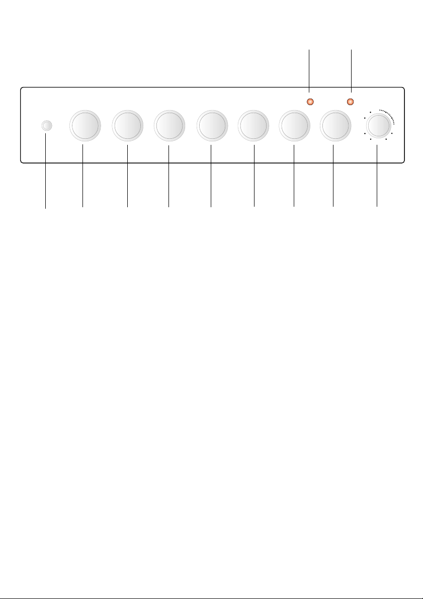
Control Panel
1110
0
54
51
0
3
1
2
1. Electric ignition push button
2. Back left burner control knob (rapid)
3. Front left burner control knob (normal)
4. Central burner control knob (double crown)
5. Front right burner control knob (simmer)
6. Back right burner control knob (normal)
7. Oven function control knob
8. Thermostat control knob
9. Timer control knob
10. General control lamp
11. Thermostat control lamp
76543
8 9
4
Page 5
Operation
Hob burners
To light a burner:
- turn the relevant control knob
anticlockwise to maximum position.
- At the same time push the electric
ignition button which is marked with a
little spark.
- Upon ignition, keep the knob pushed
down about 5 seconds: this will allow
the thermocouple to be heated and the
safety device to be switched off,
otherwise the gas supply would be
interrupted.
- Then adjust the flame as required.
If the burner does not ignite, turn the control
knob to zero, and try again.
When switching on the mains, after
installation or a power cut, it is quite normal
for the spark generator to be activated
automatically.
To ensure maximum burner efficiency, you
should only use pots and pans with a flat
bottom fitting the size of the burner used
(see table).
Burner minimum maximum
diameter diameter
Large (rapid) 180 mm. 260 mm.
Medium (semi-rapid) 120 mm. 240 mm.
Small (Auxiliary) 80 mm. 160 mm.
Central (Double crown) 180 mm. 260 mm.
If you use a saucepan which is smaller than
the recommended size, the flame will
spread beyond the bottom of the vessel,
causing the handle to overheat.
As soon as a liquid starts boiling, turn
down the flame so that it will barely keep
the liquid simmering.
Take care when frying food in hot oil or
fat, as the overheated splashes could
easily ignite.
If the control knobs become difficult to turn,
please contact your local Service Centre.
5
Page 6
Electric Oven
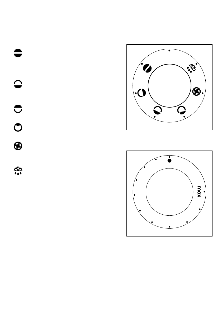
Oven Function Control Knob
0 Oven switched off
Conventional cooking - The heat
comes from both the top and bottom
element, ensuring even heating
inside the oven.
Bottom heating element - The heat
comes from the bottom of the oven
only
Top heating element - The heat
comes from the top of the oven only
Grill - The heat comes only from the
top element.
Fan cooking - This function allows
you to roast o r roast and bake
simultaneously using any shelf.
0
FO 2456
Defrosting - This function can also
be used to assist in thawing of
frozen food.
Thermostat Control Knob
Turn the thermostat control knob clockwise
to select temperatures between 50°C and
250°C (MAX).
Things to note
l The oven light will come on when the
oven function control knob is set.
l The thermostat control light will remain
on until the correct temperature is
reached. It will then cycle on and off to
show that temperature is being
maintained.
6
0
5
0
0
1
2
0
5
1
0
0
FO 1098
Page 7
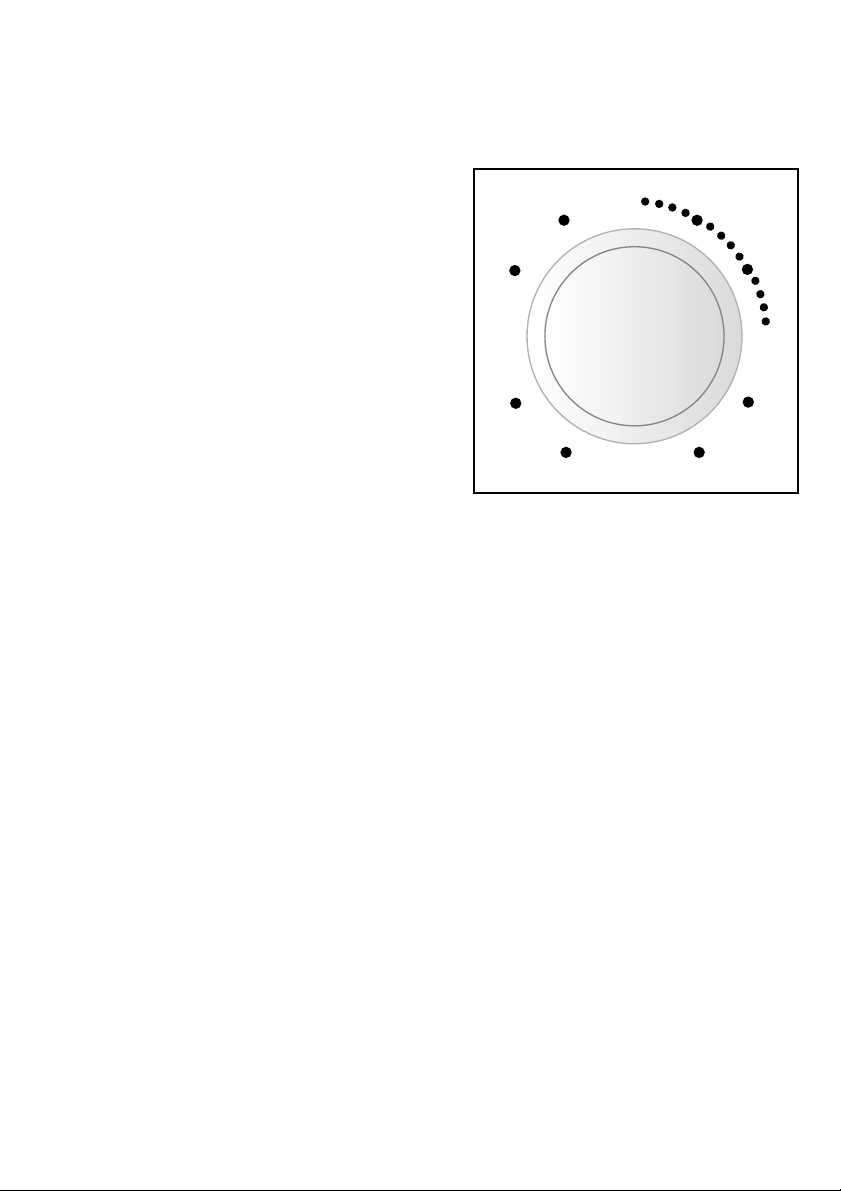
Minute minder
The minute minder will mark the end of a
timed period with an acoustic alarm. The
maximum timing is 60 minutes.
Turn the Minute Minder knob clockwise to
the maximum time position, then turn it back
to the required time.
The Minute minder will not affect in any way
the oven operation, if it is in use.
0
54
0
3
51
FO 2327
7
Page 8
Before the First Use of the Oven
Remove all packaging, both inside and
outside the oven, before using the oven.
Before first use, the oven should be heated
without food. During this time, an
unpleasant odour may be emitted. This is
quite normal.
1. Switch the oven function control knob
to conventional cooking .
2. Set the thermostat control knob to MAX.
3. Open a window for ventilation.
4. Allow the oven to run empty for
approximately 45 minutes.
This procedure should be repeated with the
fan cooking and grill function for
approximately 5-10 minutes.
Using the Oven
Always cook with the oven door closed.
Stand clear when opening the drop
down oven door. Do not allow it to
fall open - support the door using the
door handle, until it is fully open.
The oven has fourteen shelf levels.
The shelf positions are counted from the
bottom of the oven.
Do not place cookware directly on the
oven base.
8
FO 2079
Page 9

Hints and Tips
Condensation and steam
When food is heated it produces steam in
the same way as a boiling kettle. The oven
vents allow some of this steam to escape.
However, always stand back from the
oven when opening the oven door to
allow any build up of steam or heat to
release.
If the steam comes into contact with a cool
surface on the outside of the oven, e.g. a
trim, it will condense and produce water
droplets. This is quite normal and is not a
fault with the oven.
To prevent discoloration, regularly wipe
away condensation and also soilage from
surfaces.
Cookware
Use any oven proof cookware which will
withstand temperatures of 250°C.
Baking trays, oven dishes, etc. should
not be placed directly against the grid
covering the fan at the back of the oven,
or placed on the oven base.
Do not use baking trays larger than 30
cm x 35 cm (12 in x 14 in) as they will
restrict the circulation of heat and may
affect performance.
The effects of dishes
on cooking results
Dishes and tins vary in their thickness,
conductivity, colour, etc. which affects the
way they transmit heat to the food inside
them.
A Aluminium, earthenware, oven
glassware and bright shiny utensils reduce cooking and underneath browning.
B Enamelled cast iron, anodized
aluminium, aluminium with non-stick
interior and coloured exterior and dark,
heavy utensils increase cooking and
underneath browning.
Storage Drawer (optional
accessory)
The storage drawer is located underneath
the oven cavity.
During cooking the storage drawer may
become hot if the oven is on high for a long
period of time, therefore flammable
materials such as oven gloves, tea towels,
plastic aprons etc. should not be stored in
the drawer.
Oven accessories such as baking sheets,
will also become hot, therefore care should
be taken when removing these items from
the drawer whilst the oven is in use or still
hot.
Cooker Lid (optional
accessory)
The lid is designed as a dust cover when
closed, and as a splash-back when
open. Do not use for any other purpose.
After using the cooker, the lid MUST
NOT be closed until the hob and oven
are completely cold. Do not use the lid
to switch off the gas supply. The gas
supply should always be turned off with
the control knob. Always ensure that the
lid is free of any soilage or spillage before
opening it.
9
Page 10

Using the Conventional Oven
When using this setting, heat comes from
both the top and bottom elements. This allows
you to cook on a single level and is particularly
suitable for dishes which require extra base
browning such as pizzas, quiches and flans.
Gratins, lasagnes and hotpots which require
extra top browning also cook well in the
conventional oven. This form of cooking gives
you the opportunity to cook without the fan in
operation.
How to Use the
Conventional Oven
1. Turn the oven function control knob to the
required cooking function ( ).
2. Turn the thermostat control to the required
temperature.
Top oven element only
This function is suitable for finishing cooked
dishes, e.g. lasagne, shepherds pie,
cauliflower cheese etc.
Bottom oven element only
This function is particularly useful when blindbaking pastry. It may also be used to finish off
quiches or flans to ensure the base pastry is
cooked through.
Cooking Chart - Conventional oven
Food Temperature (°C) Shelf Cooking
Positions* Time (mins)
Biscuits 170-200 6 - 8 25-30
Bread, buns, yeast, doughs 200-230 5 35-45
Casseroles 140-170 3 - 5 90-180
Cakes - small, Queen Victoria sponge 170-190 5 - 7 18-25
Cakes - madeira, rich fruit 130-180 5 90-150
Choux pastry, eclairs 200-230 7 30-35
Fish 200-230 5 - 9 20-40
Fruit pies, plate tarts, crumbles 180-210 6 50-65
Meringues 90-100 6 90-150
Milk puddings 140-160 5 90-150
Pate, terrine (in baine-marie) 160-180 1 - 3 60-90
Pizzas 200-230 3 - 5 25-30
Puff pastry, sausage rolls, vol-au-vents 230-250 6 15-25
Quiches, flans 170-200 4 - 6 50-60
Scones 230-250 7 - 8 8-12
Souffle 200-230 6 35-45
Stuffed vegetables 230-250 6 - 8 35-45
Roast meat & poultry 180-200 6
Yorkshire pudding 200-230 7 - 8 40-50
Keep food warm, heat dishes 90-100 6
* The shelf positions are counted from the bottom of the oven.
10
Page 11

Grilling
Grilling must be carried out with the
oven door closed.
How to Use the Grill
1. Turn the oven control function knob to
.
2. Turn the thermostat control knob on the
required temperature.
3. Adjust the grid and grill pan runner
position to allow for different thicknesses
of food. Position the food close to the
element for faster cooking and further
away for more gentle cooking.
Preheat the grill on a full setting for a few
minutes before sealing steaks or toasting.
Adjust the heat setting and the shelf as
necessary, during cooking.
Cooking Chart - Grilling
FOOD Grilling
Temp
(°C)
Bacon Rashers 210 2-3
Beefburgers 200 6-10
Chicken Joints 170 10-15
Chops - Lamb 180 7-10
- Pork 180 10-15
Fish - Whole Trout/Herring 170 8-12
- Fillets Plaice/Cod 170 4-6
Kebabs 180 10-15
Kidneys - Lamb/Pig 170 4-6
Liver - Lamb/Pig 170 5-10
Sausages 180 10-15
Toast 250 1-2
Heating through and
Browning, e.g. au-gratin, - -
lasagne, shepherd's pie.
Browning dishes only 230 3-5
(Mins per side)
Time
The dripping pan must be inserted on the lowest level
11
Page 12

Using the Fan Oven
The air inside the oven is heated by the
element around the fan situated behind the
back panel. The fan circulates hot air to
maintain an even temperature inside the
oven.
The advantages of cooking with this
function are:
l Faster Preheating
As the fan oven quickly reaches temperature, it is not usually necessary to preheat
the oven although you may find that you
need to allow an extra 5-7 minutes on
cooking times. For recipes which require
higher temperatures, best results are
achieved if the oven is preheated first, e.g.
bread, pastries, scones, souffles, etc.
l Lower Temperatures
Fan oven cooking generally requires lower
temperatures than conventional cooking.
Follow the temperatures recommended in
the cooking table or remember to reduce
temperatures by about 20-25°C for your
own recipes which use conventional
cooking.
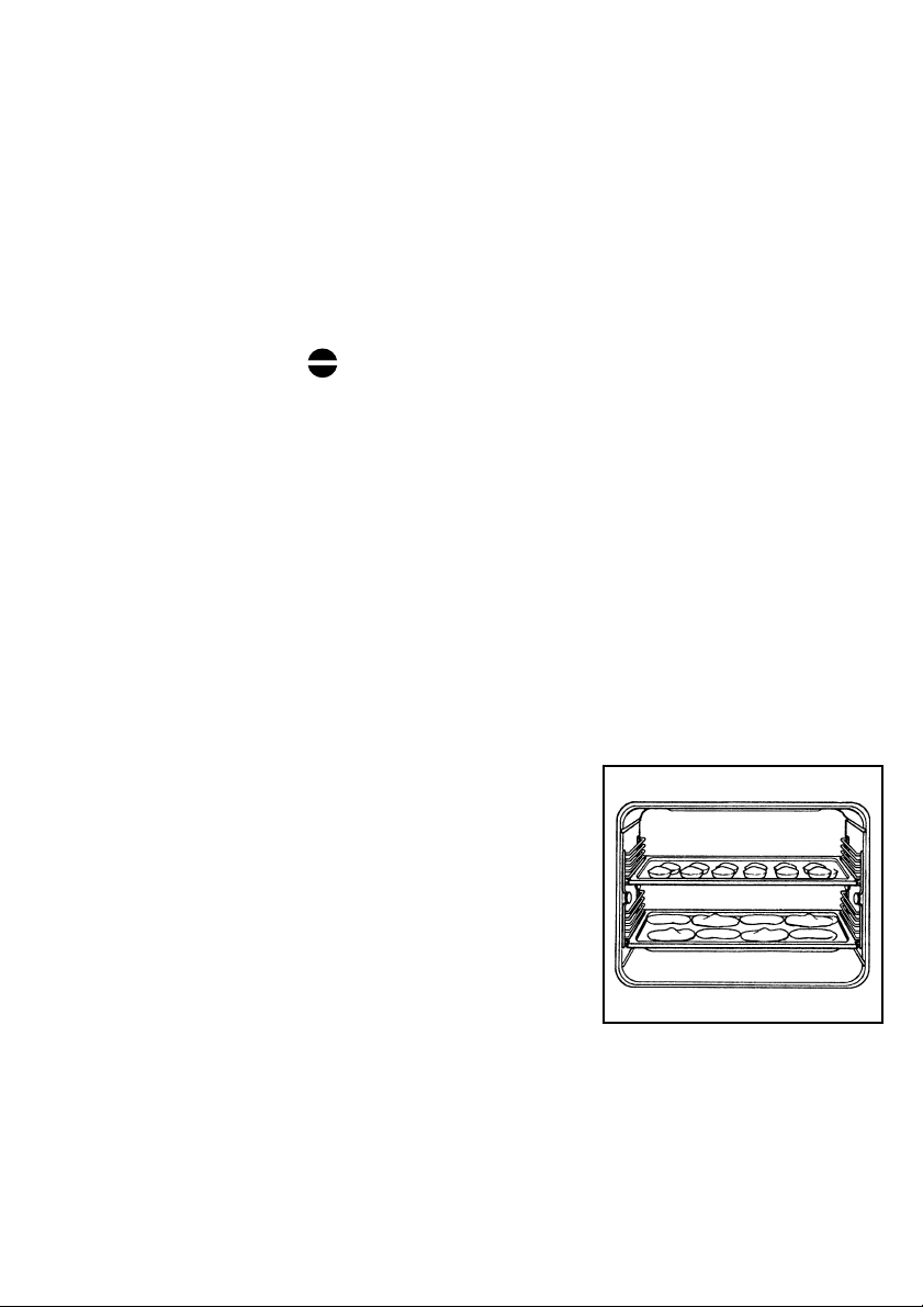
l Even Heating for Baking
The fan oven has uniform heating on all
runner positions. This means that batches
of the same food can be cooked in the oven
at the same time. However, the top shelf
may brown slightly quicker that the lower
one.
This is quite usual. There is no mixing of
flavours between dishes.
How to Use the Fan Oven
1. Turn the oven function control knob to
.
2. Turn the thermostat control to the
required temperature.
Defrosting
The oven fan operates without heat and
circulates the air, at room temperature,
inside the oven. This increases the speed
of defrosting. However, please note that the
temperature of the kitchen will influence the
speed of defrosting.
This function is particularly suitable for delicate food which could be damaged by
heat, e.g. cream filled gateaux, iced cakes,
pastries, bread and other yeast products.
How to Use Defrosting
1. Turn the oven function control knob to
.
2. Ensure the thermostat control knob is in
the OFF position.
12
Page 13

Fan Oven Cooking Chart
Food
Biscuits 160-190
Bread 190-220
Casseroles 130-140
Cakes: Small and queen 160-170
Sponges 160-170
Madeira 140-150
Rich Fruit 130-140
Christmas 130-140
Meringues 90-100
Fish 170-190
Fruit Pies and Crumbles 170-200
Milk Puddings 130-140
Pastry: Choux
Shortcrust
Flaky
Puff
Plate Tarts 180
Quiches/Flans 170-180
Scones 210-220
Roasting:Meat&Poultry 160-180
Shelf
Position
Shelf
positions
are not
critical but
ensure that
oven
shelves are
evenly
spaced
when more
than one is
used.
Cooking
Temp (°C)
190-200
REMARKS
1) Cooking times do not include preheating, we advise you, particularly for cakes,
pizzas, bread, to preheat the oven for approximately 10 minutes.
2) All cooking must be carried out with the oven door closed.
13
Page 14

Cleaning the Hob
Before any maintenance or cleaning can be
carried out, you must DISCONNECT the
hob from the electricity supply.
The hob is best cleaned whilst it is still warm,
as spillage can be removed more easily
than if it is left to cool.
The Hob Top
Regularly wipe over the hob top using a soft
cloth well wrung out in warm water to which
a little wasing up liquid has been added.
Avoid the use of the following:
- household detergent and bleaches;
- impregnated pads unsuitable for non-
stick saucepans;
- steel wool pads;
- bath/sink stain removers.
Pan Supports
When washing the pan supports, take care
when drying them as the enamelling
process occasionally leaves rough edges.
If necessay, remove stubborn stains using
a paste cleaner.
The Burners
The burner caps and crowns can be
removed for cleaning.
Wash the burners caps and crowns using
hot soapy water, and remove marks with a
mild paste cleaner. A well moistened soap
impregnated steel wool pad can be used
with caution, if the marks are particularly
difficult to remove.
After cleaning, be sure to wipe dry with a
soft cloth.
Cleaning the Oven
Before any cleaning or maintenance can
be carried out, you must disconnect the
appliance from the electricity supply.
The oven should be kept clean at all times.
A build-up of fats or other foodstuffs could
result in a fire, especially in the grill pan.
Cleaning materials
Before using any cleaning materials on your
oven, check that they are suitable and that
their use is recommended by the
manufacturer.
Cleaners that contain bleach should NOT
be used as they may dull the surface
14
Page 15

finishes. Harsh abrasives should also be
avoided.
External cleaning
Regularly wipe over the control panel, oven
door and door seal using a soft cloth well
wrung out in warm water to which a little
washing up liquid has been added.
To prevent damaging or weakening the door
glass panels avoid the use of the following:
l Household detergent and bleaches
l Impregnated pads unsuitable for
non-stick saucepans
l Steel wool pads
l Chemical oven pads or aerosols
l Rust removers
l Bath/Sink stain removers
Clean the outer and inner door glass using
warm soapy water. Should the inner door
glass become heavily soiled it is
recommended that a cleaning product is
used.
DO NOT clean the oven door while the
glass panels are warm. If this precaution
is not observed the glass panel may
shatter.
If the door glass panel becomes chipped
or has deep scratches, the glass will be
weakened and must be replaced to prevent
the possibility of the panel shattering.
Contact your local Service Centre who will
be pleased to advise further.
Grease Filter
To prevent a build-up of fats on the fan
impellor, the grease filter must be fitted by
clipping it over the vents in the back panel.
To clean the grease filter
When the oven has cooled down, remove
the filter by pushing the protruding tongue
on the filter upward, and wash carefully.
The grease filter should be cleaned after
every use. The filter may be washed in a
dishwasher on a 65°C wash. If the filter is
heavily soiled, place the filter in a saucepan
of water with approximately 1 teaspoon of
automatic washing powder or dishwasher
powder. Bring to the boil and leave to soak
for approximately 30 minutes or longer
depending on the degree of soiling. Ensure
the solution does not boil over as it could
mark your hob.
Rinse filter in clear water and dry.
Remember to refit the filter before using
the oven again.
Oven Cavity
The enamelled oven cavity is best cleaned
whilst the oven is still warm. Wipe the oven
over with a soft cloth soaked in warm soapy
water after each use. From time to time it
will be necessary to do a more thorough
cleaning, using a proprietary oven cleaner.
FO 0018
15
Page 16

Oven lamp replacement
Disconnect the appliance.
Unscrew the lamp and substitute it with
another suitable for higher temperature
(300°C) having the following characteristics:
Tension: 230-240 (50Hz); Power:15W;
Connection:E14
Shelves and shelf supports
To clean the chrome parts of the oven, soak
in warm detergent water and remove
stubborn marks with a well wetted soap
impregnated pad. Rinse well and dry with a
soft cloth. Do not use abrasive scourers or
steel wool.
Removing the oven shelf
supports
Unscrew the ring nuts securing the shelf
supports (see diagram) and remove the
supports after sliding them out of their
retaining pins.
Warning
Always unplug the appliance before
removing the back panel.
To remove the back panel use a
screwdriver. This is a good opportunity to
clean the back of the rear panel.
Wash the panels with very hot water and a
detergent using a soft cloth.
If the shelf supports or the panels become
very soiled, use a standard caustic product
specially made for cleaning ovens.
FO 0145
The Oven Door
Before cleaning the oven door, we
recommend you to remove it from the oven.
Proceed as follows:
a) open the oven door completely;
b) find the hinges linking the door to the
oven ;
c) unlock and turn the small levers located
on the two hinges;
16
d) handle the door by its left- and right-hand
sides, then slowly turn it towards the
oven until it is half-closed;
e) gently pull the oven door off its site;
f) place it on a steady plan.
Clean the oven door glass with warm water
and a softh cloth only.
Once the cleaning is carried out, refit the
oven door, following the procedure in
reverse.
Page 17

If something goes wrong
SYMPTOM
n The cooker does not operate.
n The gas ring burns unevenly
n The oven does not come on
n The oven temperature light does not come
on
n The oven light does not come on
n It takes too long to finish the dishes, or
they are cooked too fast.
SOLUTION
u Check that the unit is plugged in and the
electrical supply is switched on
u Check the mains fuse has not blown
u Check the correct control knob has been
turned.
u Check the main jet is not blocked and
the burner crown is clear of food particles.
u Check the burner cap and crown have
been replaced correctly, e.g. after cleaning.
u Check the oven is in manual operation
and that both a cooking function and temperature have been selected.
u The socket switch or the switch from the
mains supply to the cooker are ON.
u Select a temperature with the thermostat
control knob
u Select a function with the oven function
control knob.
u Select a function with the oven function
control knob
u Check the light bulb, and replace it if
necessary (see "Replacing the Oven Light")
u The temperature may need adjusting
n Steam and condensation settle on the
food and the oven cavity.
u Refer to the contents of this booklet,
especially to the chapter Using the Oven.
u Leave dishes inside the oven no longer
than 15-20 minutes after the cooking is
completed.
n The oven fan is noisy
For service, please contact your authorised local Service Agent giving full details of the
model, serial number and date of purchase. If you do not know who your local service
agent is, please call your local Sales office listed at the back of these instructions.
Please note that it will be necessary to provide proof of purchase for any in-guarantee
service calls.
In-guarantee customers should ensure that the above checks have been made as the
engineer will make a charge if the fault is not a mechanical or electrical breakdown.
u Check that shelves and bakeware are not
vibrating in contact with the oven back panel.
17
Page 18

Instructions for the Installer
Technical Data
Dimensions
Height 830/910 mm
Depth 600 mm
Width 700 mm
Oven Capacity 53 dm
Hob burners
Rapid burner back left
Semi-rapid burner front left
back right
Auxiliary burner front right
Double crown burner central
Appliance Gas Supply:
Natural Gas 1.0 kPa
Universal LPG 2.75 kPa
Oven Ratings
Top Heating Element 0.87 kW
Bottom Heating Element 1.1 kW
Grill Element 1.9 kW
3
Convection Fan 30 W
Circular element 2.18 kW
Oven light 15 W
Total rating 2.23 kW
Supply voltage (50 Hz) 230-240 V
(calculated at 240 V)
Power of gas burners
TYPE TYPE NOZZLE NOMINAL NOMINAL
OF GAS OF BURNER MARKS GAS PRESSURE
1/100 mm CONSUMPTION kPa
MJ/h
NATURAL
GAS
U-LPG
18
Double Crown (wok) 1.50 11.00
Rapid (large) 1.35 9.00
Semi-rapid (medium) 1.11 6.80 1.00
Auxiliary (small) 0.89 3.80
Double Crown (wok) 0.93 11.00
Rapid (large) 0.88 10.00
Semi-rapid (medium) 0.71 6.30 2.75
Auxiliary (small) 0.55 3.60
Page 19

Location
Choose a location free of draughts and
open doors and clear of combustible
materials or other fire hazards such as
curtains, etc. The location should ensure
convenience of operation and service. Any
adjacent wall surface situated within
200mm from the edge of any hob burner
and above the height of the hob must be a
suitable non-combustible material for a
height of 150 mm for the entire depth and
width of the cooker. If the hob is below the
bench top, a clearance of 100 mm must be
provided.
Any combustible material above the
hotplate must be at least 650 mm above
the top of the hob and no construction shall
be within 450 mm above the top of the
burner.
100
100
650
500
100
500
650
19
Page 20

Feet Assembly
Before installing the cooker, it is necessary
to assemble the supplied feet. You can find
them into the oven cavity.
1. Remove the hob pan supports, the
burner caps and crowns and the oven
accessories.
2. Carefully lean the cooker on its back (Fig.
1), paying attention not to cause any
damage.
3. Adjust the feet height. A height indicator
is printed on the last page of this
Instruction book (Fig. 2). Lean the foot
on the page and make the foot match
with the indicator, then unscrew the
bottom part of the foot, until you obtain
the required height. Repeat the same
operation with the other feet.
4. Screw the feet into the relevant holes
indicated in figure 1.
5. Lift the cooker in vertical position.
Replace the crowns, the burner caps, the
hob pan supports and the oven
accessories.
6. If necessary, adjust the cooker horizontal
levelling by turning the bottom part of the
feet, until the appliance is completely
stable. (Fig. 3). A spirit level should be
placed on a cake tray on one of the
shelves to confirm that the appliance is
correctly levelled.
Fig. 1
Fig. 2
830
840
850
860
870
880
890
900
910
FO 2284
20
Fig. 3
FO 2285
Page 21

Splash back Assembly
A stainless steel splash back is supplied
with the appliance. This is meant to be fitted
on the rear edge of the cooker's hob. The
splash back is inserted into the polystyrene
upper part of the package.
1. Carefully clean the hob top.
2. A foam rubber gasket is supplied into
the instruction book envelope.
3. After cleaning the hob from possible
grease and film residuals left, fix the
gasket on the rear part of the hob, paying
attention not to close the fan slots (Fig.
4).
4. Take the splash back out of the envelope
and remove the protective film.
5. Insert the splash back into the proper
hinges in the rear part of the hob (Fig.
5).
6. Fix the splash back with the supplied
screws (Fig. 6).
Fig. 4
Fig. 5
FO 2347
FO 2286
Fig. 6
FO 2287
21
Page 22

Fitting the Stability Bracket
The stability bracket supplied with the
cooker must be fitted by the installer (see
Fig.7).
165 mm
1. Place the cooker in its intended position
and mark the cooker height.
2. Mark 165mm below the cooker height.
This is the position of the stability
bracket.
3. Fix the stability bracket (using two of the
provided five fixing holes) to the rear wall
(see diagram).
4. Pull the cooker towards the rear wall as
shown in the diagram. The stability
bracket should then come into contact
with the rear panel of the cooker.
Check that the stability bracket securely
prevents the cooker from accidently tipping
forward when a downward force is applied
to the open oven door.
REAR WALL
Fig. 7
22
Page 23

Installation
Important
This cooker must be installed by qualified
personnel.
The manufacturer will not accept liability,
should the above instructions or any of the
other safety instructions incorporated in this
book be ignored.
Regulations
This appliance shall be installed in
accordance with the manufacturers
installation instructions, local gas fitting
regulations, municipal building codes,
AS5601 (AG601) and any other relevant
statutory regulations.
Data label
The data label is located centrally on the
front frame of the cooker below the oven.
This appliance is suitable for Natural or
Universal LPG. Ensure that the gas supply
matches the data label.
Ventilation
Ventilation must be in accordance with
AS5601 (AG601) Installation Code. In
general, the appliance should have
adequate ventilation for complete
combustion of gas, proper flueing and to
maintain temperature of immediate
surroundings within safe limits.
Connection to the gas
supply
Gas connection must be carried out in
conformity with the regulations in force. The
appliance leaves the factory tested and
regulated for the type of gas indicated on
the plate which is situated in the lower
position near the gas connection tube.
Ascertain that the type of gas with which
the appliance will be supplied is the same
as that indicated on the plate.
If different carry out all the operations
according to the indications cited in the
paragraph adaption to different types of
gas.
For a maximum output and minimum
consumption ascertain that the pressure of
the gas used has the values indicated in
the table of burner characteristics.
The joint is mounted on the intake area of
the pipe, fitted with a filleted nut GJ 1/2,
between the sealing components. Screw
the parts without forcing, turn the joint in
the direction required and then tighten
everything.
23
Page 24

Connection
Carry out the connection to the gas plant
only by means of a rigid metallic pipe
conforming to the regulations in force.
The joint for the entry of gas into the
appliance is threaded GJ 1/2".
Carry out the connection avoiding any type
of stress on the appliance.
Natual gas appliances must be fitted with a
pressure regulator and be installed at the
inlet connection. The gas pressure must
then be set as a part of the commissioning
procedures.
For U-LPG the pressure adjustment is
made via the regulator fitted at the domestic
cylinder.
Important
Upon completion of installation, always
check:
l that all the joints are completely sealed
by using a soapy solution, never a flame;
l that the gas pressure has been
regulated to 1.00kPa for Natural Gas
and 2.75kPa for Universal-LPG. The
pressure test point is located on the
regulator for Natural Gas models or at
the top left hand rear of the cooker for
U-LPG models. The pressure should be
measured and adjusted with the Wok
burner on high flame;
l that the automatic ignition system is
operating satisfactory on all burners,
both individually and in combination;
l that the burners operate correctly, are
stable, without yellow tipping or
excessive noise on high and low flame.
Then demonstrate to the customer the
appiance operation and leave these
instructions.
24
Page 25

Adaptation to different types of gas
WARNING: Servicing shall only be
carried out by authorised personnel.
Substitution of the nozzles
- Remove the grills;
- Remove the caps and baffles from the
burners;
- With a tubular spanner no. 7 unscrew
and remove (fig. 8) the nozzles
substituting them with those
corresponding to the type of gas used
(see table on page 18);
- Remount the parts carrying out the
operations described in reverse. Upon
completion remove existing gas type
label and stick the relevant gas type label
near the gas supply pipe.
If the pressure of gas used is different (or
variable) from that foreseen an appropriate
pressure regulator should be installed on
the entry tube. In case pressure regulators
for U-LPG are used these should conform
to the regulations in force.
Regulation of the minimum
To regulate the minimum:
- bring the tap to the minimum flame
position.
- extract the knob.
- in case of conversion from natural gas
to U-LPG, tightly screw the by-pass
screw (Fig.9);
- when converting from U-LPG to natural
gas unscrew about ½ turn by-pass
screw, until a regular small flame is
reached.
Finally check that by quickly turning the
tap from the maximum position to the
minimum position the burner is not
extinguished; remount the parts carrying
out the operations described in reverse.
Tap
Fig. 8
By pass screw
Burner Ø By-pass
of tap
1/100 mm
Auxiliary 28
Semi-rapid 35
Rapid 45
Double crown 56
FO 0392
Fig. 9
25
Page 26

Electrical connections
The appliance is predisposed to function
with a 230-240V monophase voltage
tension. Connection must be carried out in
conformity with the regulations and
dispositions of the laws in force.
Before connecting ensure that:
- The limiter valve and the electrical mains
can support the voltage of the appliance
(see registration plate).
- The power supply is correctly earthed
according to the regulations in force.
- The plug or omnipolar interrupter used
can be easily reached once the
appliance has been installed.
The appliance is supplied with a supply cord
incorporating a plug. Connect the plug to
an appropriate security socket.
If a direct connection to the mains is
required, an omnipolar interrupter with a
minimum opening of 3mm between
contacts, dimensioned to the voltage and
corresponding to the regulations in force,
should be interposed between the appliance
and the supply. The yellow/green earth
cable must not be interrupted by the
interrupter. The brown coloured phase
cable (situated at terminal L of the terminal
box) must always be connected to the
network phase. The voltage cable must
always be positioned in such a manner that
it at no point reaches a temperature of
50 °C above room temperature. An example
of the best routing is shown in fig. 11.
In case of substitution of the voltage cable
use cable type H05 RRF having a section
suited to the charge, it is furthermore
necessary that the yellow/green earth wire
be approximately 2cm longer than the
phase and neutral wires (Fig. 10).
After connection try out the heating
elements allowing them to function for
approximately 3 minutes.
26
Fig.10
Neutral wire
Phase
Ground (yellow - green)
Fig.11
FO 0480
YES
Gas
pipeline
Electric
wire
Gas
pipeline
Electric
wire
Gas
pipeline
Electric
wire
NO
The manufacturer declines all
responsibility in case the prevention of
accidents regulations are not respected.
Page 27

SALES, TECHNICAL, SERVICE AND SPARE PARTS ASSISTANCE
NEW SOUTH WALES
Head Office, Sales Office and Showroom*
2 Costello Place
Seven Hills NSW 2147
PO Box 888
Seven Hills NSW 1730
Telephone: 02 8825 9494
Facsimile: 02 9674 8697
Service and Spare Parts
All General Whitegoods Service
Telephone: 02 9756 1511
Facsimile: 02 9756 1091
AUSTRALIAN CAPITOL TERRITORY
Service and Spare Parts
Premier Appliance
Telephone: 06 280 5087
Facsimile: 06 280 6783
VICTORIA
State Office and Showroom*
35 Centre Road
Scoresby VIC 3179
Telephone: 03 8756 7800
Facsimile: 03 8756 7899
Service and Spare Parts
Advantage Appliances
Telephone: 03 9543 2088
Facsimile: 03 9544 2102
QUEENSLAND
State Office and Showroom*
Ground Floor, Building 1
Bowengate Business Park
Cnr Bowen Bridge Road & Campbell Street
Bowen Hills QLD 4006
Telephone: 07 3253 2000
Facsimile: 07 3216 1688
Service and Spare Parts
Tri-Us Appliance Repairs
Telephone: 07 3274 3931
Facsimile: 07 3287 7287
SOUTH AUSTRALIA
For sales assistance contact Victorian office
Service and Spare Parts
Prestige Appliance Repair Centre
Telephone: 08 8352 2022
Facsimile: 08 8353 3044
WESTERN AUSTRALIA
Sales Agent
TCB Sales and Marketing
199 Abernathy Road
Belmont WA 6104
Telephone: 08 9478 1293
Facsimile: 08 9478 3018
Service and Spare Parts
Phipps Electrical Services
Telephone: 08 9470 1175
Facsimile: 08 9361 6335
TASMANIA
Sales Agent
Mark Pearce Agencies
23 Tranmere Road
Howrah TAS 7018
Telephone: 03 6247 9215
Facsimile: 03 6247 9215
Service and Spare Parts
Northern Electrical Services
Telephone: 03 6331 3971
Facsimile: 03 6331 3992
TOLL FREE NUMBERS
Customer Service: 1800 646 843
Spare Parts: 1800 461 462
* Showrooms open six days a week
27
Page 28

830
840
Height indicator for
feet adjustment
850
860
870
880
890
900
Total cooker height
910
830
840
850
860
870
880
890
900
910
Follow the instructions.
Warning! The installation
must be carried out by
quialified personnel only!
35673-8802 07/01
 Loading...