

Page 1
Turbine Flow Meter
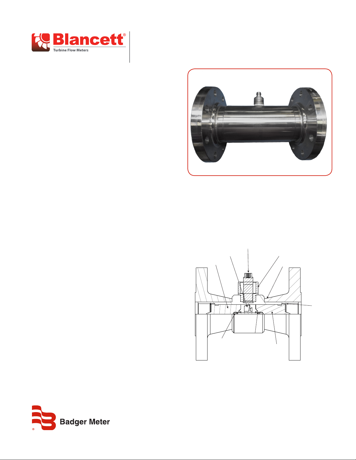
Model 1100 Flanged Connections
DESCRIPTION
The Model 1100 turbine flow meter is designed to withstand the
demands of the most rigorous flow measurement applications.
Originally developed for the secondary oil recovery market,
the Model 1100 flow meter is an ideal meter for liquid flow
measurement on or off the oil field.
The meter features a rugged 316 stainless steel housing and rotor
support assemblies, 304 stainless steel flanges CD4MCU stainless
steel rotor, and abrasive-resistant tungsten carbide rotor shaft and
journal bearings. The Model 1100 meter maintains measurement
accuracy and mechanical integrity in the corrosive and abrasive
fluids commonly found in oil field water flood projects and many
industrial applications.
When paired with a Blancett flow monitor, the Model 1100 turbine
meter meets a wide range of measurement requirements. This
makes it ideal for applications such as pipelines, production/
injection fields, mining operations, offshore facilities, and other
industrial applications. For a full list of Blancett flow monitors, see
www.badgermeter.com.
FEATURES
• Offers accurate and repeatable flow measurement in ranges
from 5…5000 gpm (170…170,000 bpd)
• Cost-effective solution for turbine flow meter applications
• Rugged 316 stainless steel body and 304 stainless steel
flange construction offers long service life in severe
operating environments
• Flange end connections
• NIST traceable calibration
• Installation in pipe sizes from 1…10 in.
• Can integrate electronically with a Blancett flow monitor
• K-factor Scaler, or the F to I/F to V Intelligent Converter Field
replaceable repair kits allow for turbine replacement without
loss of accuracy
INSTALLATION
OPERATING PRINCIPLE
Fluid entering the meter passes through the inlet flow straightener
that reduces its turbulent flow pattern and improves the fluid’s
velocity profile. Fluid then passes through the turbine, causing
it to rotate at a speed proportional to fluid velocity. As each
turbine blade passes through the magnetic field at the base of the
transducer, an AC voltage pulse is generated in the pickup coil.
These pulses produce an output frequency proportional to the
volumetric flow through the meter.
Magnetic Pick-up
Conduit Adaptor
Meter Body
Retaining
Ring
Groove
*Upstream
Rotor Support
*R otor and
Rotor Shaft
The Model 1100 turbine meter is simple to install and service. It
operates in any orientation (horizontal to vertical) as long as the
“flow direction” arrow is aligned in the same direction as the actual
line flow. For optimum performance, the flow meter should be
installed with a minimum of 10 diameters upstream straight pipe
length and 5 diameters downstream straight pipe length.
TRB-DS-02738-EN-03 (April 2018)
*Thrust Ball
NOTE: *Indicates parts supplied in repair k its.
*B earing
*D ownstream
Rotor Support
Figure 1: Meter components
Product Data Sheet
Page 2

Turbine Flow Meter, Model 1100 Flanged Connections
+1%
+%
AVG. K-FACTOR (K)
-%
STANDARD TURNDOWN APPROX. 10:1
KFACTOR
The K-factor represents the number of output pulses transmitted per gallon of fluid passing through the turbine meter. Each turbine has a
unique K-factor. However, turbine meters are not functionally consistent throughout the full flow range of the meter.
There are several forms of friction inherent in the turbine meters that retard the rotational movement of the turbine rotor. These frictional
forces include: magnetic drag, created by electromagnetic forces of pickup transducers; mechanical drag, due to bearing friction; and
viscous drag, produced by flowing fluid.
As flow increases, the frictional forces are minimized and the free-wheeling motion of the turbine rotor becomes more linear (proportional
to flow). The K-factor becomes relatively constant and the linear throughout the balance of the linear flow range. This is approximately a
10:1 turndown ratio from the maximum flow rate down to the minimum flow rate.
Typical K-factor Curve (Pulse per US Gallon)
100%
RATE
(CYCLES/SEC)
FLOW
AT
(CYCLES/GALLON)
LUE
A
50%
V
FREQUENCY
CTOR
A
OF
%
K-F
OUTPUT
0% 10%
K-FACTOR (PULSES/GALLON)
50%
FULL FLOW RANGE
LINEAR FLOW RANGE
100%
LINEARITY (DESIGN DEVIATION)
-1%
K
-
F
A
C
T
O
R
(
P
S
U
L
)
N
O
L
L
A
G
/
E
SPECIFICATIONS
Body 316 stainless steel
Rotor CD4MCU stainless steel
Construction Materials
Turndown Ratio 10:1
Flow Accuracy ±1% of reading
Repeatability ±0.1%
Calibration Water (NIST traceable calibration)
Pressure Rating 5000 psi max.
Turbine Temperature –150…350° F (–101…177° C)
Flange End Connections 150, 300, 600, 900, 1500; PN 40
Certifications
(see NOTE below)
* Contact factory for ordering options
NOTE: Certifications do not apply to DIN flange models.
Rotor Support 316 stainless steel
Rotor Shaft Tungsten carbide
Flanges 304 stainless steel
CSA Class I Div 1, Groups C & D
Class II Div 1, Groups E, F & G: intrinsically safe*
CSA Class I Div 1, Groups C & D; complies with UL 1203 and CSA 22.2 No. 30
Met Labs File No. E112860 (for explosion-proof models only)
TRB-DS-02738-EN-03Page 2 April 2018
Page 3

PART NUMBER CONSTRUCTION
B xxx-xxx - FA
DN 250
Flange
Flange
Flange
Model 1100 Turbine Flow Meters with 304 SS Flange Connections
Part Number Construction
Insert Flow Meter
Part Number
Part
Number
B111-110 1 in.
B111-115 1-1/2 in.
B111-121 2 in. LF
B111-120 2 in.
B111-130 3 in.
B111-140 4 in.
B111-160 6 in.
B111-180 8 in.
B111-200 10 in.
Meter
Size
Bore Size
1 in.
(25.4 mm)
1-1/2 in.
(38.1 mm)
1-1/2 in.
(38.1 mm)
2 in.
(50.8 mm)
3 in.
(76.2 mm)
4 in.
(101.6 mm)
6 in.
(152.4 mm)
8 in.
(203.2 mm)
10 in.
(254 mm)
Size
A
1”
DN 25
B
1½”
DN 40
C
2”
DN 50
D
3”
DN 80
E
4”
DN 100
F
6”
DN 150
G
8”
DN 200
H
10”
GPM (LPM) BPD M3/D Mesh Pulse/Gal
5…50
(18.9…189.3)
15…180
(56.8…681.4)
15…180
(56.8…681.4)
40…400
(151.4…1514.2)
60…600
(227.1…2271.2)
100…1200
(378.5…4542.5)
200…2500
(757.1…9463.5)
350…3500
(1324.9…13248.9)
500…5000
(1892.7…18927.1)
Rating
A
B
C
D
E
K
150#
300#
600#
900#
1500#
PN 40
Type
ADRaised Face
Din Flange
Flow Ranges Strainer
170…1700 27.25…272.5 40 870 8…20
515…6000 82…981 20 330 12…32
515…6000 82…981 20 330 15…55
1300…13000 218…2180 20 52 18…58
2100…21000 327…3270 10 57 30…108
3400…41000 545…6540 10 29 43…163
6800…86000 1090…13626 4 7 89…380
12000…120,000 1363…19076 4 3 127…587
17000…171,000 2725…27252 4 1.6 172…958
Approx.
K-factor
Meter
Weight
(lb)
End-to-End
Length
6 in.
(152.4 mm)
7 in.
(177.8 mm)
7 in.
(177.8 mm)
8.5 in.
(215.9 mm)
10 in.
(254.0 mm)
12 in.
(304.8 mm)
12 in.
(304.8 mm)
12 in.
(304.8 mm)
12 in.
(304.8 mm)
TRB-DS-02738-EN-03 Page 3 April 2018
Page 4

Turbine Flow Meter, Model 1100 Flanged Connections
Control. Manage. Optimize.
Blancett is a registered trademark of Badger Meter, Inc. Other trademarks appearing in this document are the property of their respective entities. Due to continuous research,
product improvements and enhancements, Badger Meter reserves the right to change product or system specications without notice, except to the extent an outstanding
contractual obligation exists. © 2018 Badger Meter, Inc. All rights reserved.
www.badgermeter.com
The Americas | Badger Meter | 4545 West Brown Deer Rd | PO Box 245036 | Milwaukee, WI 53224-9536 | 800-876-3837 | 414-355-0400
México | Badger Meter de las Americas, S.A. de C.V. | Pedro Luis Ogazón N°32 | Esq. Angelina N°24 | Colonia Guadalupe Inn | CP 01050 | México, DF | México | +52-55-5662-0882
Europe, Eastern Europe Branch Oce (for Poland, Latvia, Lithuania, Estonia, Ukraine, Belarus) | Badger Meter Europe | ul. Korfantego 6 | 44-193 Knurów | Poland | +48-32-236-8787
Europe, Middle East and Africa | Badger Meter Europa GmbH | Nurtinger Str 76 | 72639 Neuen | Germany | +49-7025-9208-0
Europe, Middle East Branch Oce | Badger Meter Europe | PO Box 341442 | Dubai Silicon Oasis, Head Quarter Building, Wing C, Oce #C209 | Dubai / UAE | +971-4-371 2503
Slovakia | Badger Meter Slovakia s.r.o. | Racianska 109/B | 831 02 Bratislava, Slovakia | +421-2-44 63 83 01
Asia Pacic | Badger Meter | 80 Marine Parade Rd | 21-06 Parkway Parade | Singapore 449269 | +65-63464836
China | Badger Meter | 7-1202 | 99 Hangzhong Road | Minhang District | Shanghai | China 201101 | +86-21-5763 5412
Switzerland | Badger Meter Swiss AG | Mittelholzerstrasse 8 | 3006 Bern | Switzerland | +41-31-932 01 11
 Loading...