

Page 1

BLADEOS™ 6.5
Application Guide
RackSwitch™ G8124/G8124-E
Part Number: BMD002 20, October 2 010
2051 Mission Colle ge B lv d.
Santa Clara, CA 95054
www.bladenetwork.net
Page 2

BLADEOS 6.5.2 Application Guide
Copyright © 2010 BLADE Network Technologies, Inc., 2051 Mission College Blvd., Santa Clara,
California, 95054, USA. All ri ghts reserved. Part Number: BM D00220.
This document is protected by copyright and distributed under licenses restricting its use, copying,
distribution, and decompilation. No part of this document may be reproduced in any form by any
means without prior written autho rization of BLADE Network T echn ologies, Inc. Documentatio n is
provided “as is” without warra nty of any kind, eith er express or implied, incl uding any kind of
implied or express warranty o f non-infringement or the imp lied warranties of merchantabi lity or
fitness for a particular purpose.
U.S. Government End Users: This document is provided with a “commercial item” as defined by
F AR 2.101 (Oct. 1995) and contains “commercial technical data” and “commercial software
documentation” as those terms are used in FAR 12.211-12.212 (Oct. 1995). Government End Users
are authorized to use th is documentation only in accordance with tho se rights and restrictions set forth
herein, consistent with FAR 12.211- 12.212 (Oct. 1995), DF ARS 227.7202 (JUN 1995) and
DF ARS 252.227-701 5 (Nov . 19 95).
BLADE Network Technologies, Inc. reserves the right to change any products described herein at any
time, and without notice. BL ADE Network T echnologies, Inc. assumes no responsibi lity or liability
arising from the use of produ cts described herein, exc ept as expressly agreed to in writing b y BLADE
Network Technologies, Inc. The use and purchase of this product does not convey a license under any
patent rights, trademar k rights, or any other in tellectual proper ty rights of BLADE Network
T echnologie s, Inc.
BLADE Network T echnologi es, the BLADE logo, BLADEHarmo ny , BNT , NMotion, RackSwitc h,
Rackonomics, RackSwitch Solution Partner , ServerMob ility , SmartConnect an d VMready are
trademarks of BLADE Network Technologies, Inc. in the United States and certain other countries.
®
and EtherChannel® are registered trademarks of Cisco Systems, Inc. in the United States and
Cisco
certain other countries. VMware is a registered trademark or trademark of VMware, Inc. in the United
States an d/or other ju risdictions . Any other tra demarks ap pearing in thi s manual ar e owned by the ir
respective companies.
Originated in the USA.
2 BMD00220, October 2010
Page 3

Contents
Preface 17
Who Should Use This Guide
What You’ll Find in This Guide
Additional References
20
Typographic Conventions
How to Get Help
22
17
17
21
Part 1: Getting Started 23
Chapter 1: Switch Administration 25
Administration Interfaces
Command Line Interface
Browser-Based Interface
Establishing a Connection
Using the Switch Management Ports
Using the Switch Data Ports
Using Telnet
30
Using Secure Shell
Using a Web Browser
Configuring HTTP Access to the BBI
Configuring HTTPS Access to the BBI
BBI Summary
Using Simple Network Management Protocol
BOOTP/DHCP Client IP Address Services
Global BOOTP Relay Agent Configuration
Domain-Specific BOOTP Relay Agent Configuration
Switch Login Levels
Setup vs. the Command Line
25
26
26
27
27
29
31
32
32
32
34
36
37
38
39
35
37
BMD00220, October 2010 3
Page 4

BLADEOS 6.5.2 Application Guide
Chapter 2: Initial Setup 41
Information Needed for Setup
Default Setup Options
42
Stopping and Restarting Setup Manually
Setup Part 1: Basic System Configuration
Setup Part 2: Port Configuration
Setup Part 3: VLANs
46
Setup Part 4: IP Configuration
IP Interface s
Default Gateways
IP Routing
47
49
49
Setup Part 5: Final Steps
Optional Setup for Telnet Support
41
42
43
44
47
50
51
Part 2: Securing the Switch 53
Chapter 3: Securing Administration 55
Secure Shell and Secure Copy
Configuring SSH/SCP Features on the Switch
Configuring the SCP Administrator Password
Using SSH and SCP Client Commands
SSH and SCP Encryption of Management Messages
Generating RSA Host and Server Keys for SSH Access
SSH/SCP Integration with Radius Authentication
SSH/SCP Integration with TACACS+ Authentication
SecurID Support
End User Access Control
61
62
Considerations for Configuring End User Accounts
Strong Passwords
User Access Control
Listing Current Users
62
63
64
Logging into an End User Account
55
56
57
57
64
59
60
60
61
62
4 Contents BMD00220, October 2010
Page 5

BLADEOS 6.5.2 Application Guide
Chapter 4: Authentication & Authorization Protocols 65
RADIUS Authentication and Authorizati on
How RADIUS Authentication Works
Configuring RADIUS on the Switch
65
66
66
RADIUS Authentication Features in BLADEOS
Switch User Accounts
68
RADIUS Attributes for BLADEOS User Privileges
TACACS+ Authentication
How TACACS+ Authentication Works
69
69
TACACS+ Authentication Features in BLADEOS
Authorization
Accounting
Command Authorization and Logging
70
71
71
Configuring TACACS+ Authentication on the Switch
LDAP Authentication and Authorization
Chapter 5: Access Control Lists
Summary of Packet Classifiers
Summary of ACL Actions
78
76
Assigning Individual ACLs to a Port
ACL Order of Precedence
ACL Metering and Re-Marking
ACL Port Mirroring
80
Viewing ACL Statistics
ACL Configuration Examples
VLAN Maps
82
Using Storm Control Filters
78
79
80
81
84
73
75
78
67
68
70
72
BMD00220, October 2010 Contents 5
Page 6

BLADEOS 6.5.2 Application Guide
Part 3: Switch Basics 85
Chapter 6: VLANs 87
VLANs Overview
VLANs and Port VLAN ID Numbers
VLAN Numbers
PVID Numbers
VLAN Tagging
88
88
88
89
90
VLAN Topologies and Design Considerations
VLAN Configuration Rules
Multiple VLANs with Tagging Adapters
VLAN Configuration Example
Private VLANs
Private VLAN Ports
98
98
Configuration Guidelines
Configuration Example
Chapter 7: Ports and Trunking
Trunking Overview
102
Before You Configure Static Trunks
Trunk Group Configuration Rules
Port Trunking Example
104
Configurable Trunk Hash Algorithm
Link Aggregation Control Protocol
94
95
97
99
99
101
103
104
106
107
94
Chapter 8: Spanning Tree Protocols
Spanning Tree Protocol Modes
Global STP Control
STP/PVST+ Mode
Port States
110
111
111
Bridge Protocol Data Units
109
112
Bridge Protocol Data Units Overview
Determining the Path for Forwarding BPDUs
Fast Uplink Convergence
Port Fast Forwarding
Simple STP Configuration
6 Contents BMD00220, October 2010
113
114
115
109
112
112
Page 7

Per-VLAN Spanning Tree Groups 117
Using Multiple STGs to Eliminate False Loops
STP/PVST+ Defaults and Guidelines
Adding a VLAN to a Spanning Tree Group
Creating a VLAN
Rules for VLAN Tagged Ports
119
119
Adding and Removing Ports from STGs
Switch-Centric Configurati on
Configuring Multiple STGs
Rapid Spanning Tree Protocol
Port State Changes
124
RSTP Configuration Guidelines
RSTP Configuration Example
122
124
121
125
125
Per-VLAN Rapid Spanning Tree Groups
Configuring PVRST
Multiple Spanning Tree Protocol
MSTP Region
127
Common Internal Spanning Tree
MSTP Configuration Guidelines
MSTP Configuration Example 1
MSTP Configuration Example 2
Port Type and Link Type
Edge Port
Link Type
131
131
126
127
127
128
128
129
131
BLADEOS 6.5.2 Application Guide
117
118
118
120
126
Chapter 9: Quality of Service
QoS Overview
Using ACL Filters
133
135
Summary of ACL Actions
ACL Metering and Re-Marking
Using DSCP Values to Provide QoS
Differentiated Services Concept s
Per Hop Behavior
QoS Levels
139
138
DSCP Re-Marking and Mapping
DSCP Re-Marking Configuration Example
Using 802.1p Priority to Provide QoS
Queuing and Scheduling
BMD00220, October 2010 Contents 7
143
133
135
136
137
137
140
141
142
Page 8

BLADEOS 6.5.2 Application Guide
Part 4: Advanced Switching Features 145
Chapter 10: Deployment Profiles 147
Available Profiles
Selecting Prof ile s
147
149
Automatic Configuration Changes
Chapter 11: Virtualization
Chapter 12: Virtual NICs
Defining Server Ports
154
Enabling the vNIC Feature
vNIC IDs
155
vNIC IDs on the Switch
151
153
154
155
vNIC Interface Names on the Server
vNIC Bandwidth Metering
vNIC Groups
157
vNIC Teaming Failover
vNIC Configuration Example
156
159
161
vNICs for iSCSI on Emulex Eraptor 2
Chapter 13: VMready
165
149
155
164
VE Capacity
Defining Server Ports
VM Group Types
Local VM Groups
Distributed VM Groups
VM Profiles
166
166
166
167
169
169
Initializing a Distributed VM Group
Assigning Members
170
Synchronizing the Configuration
Removing Member VEs
171
Virtualization Management Servers
Assigning a vCenter
vCenter Scans
Deleting the vCenter
Exporting Profiles
172
173
173
174
VMware Operational Commands
Pre-Provisioning VEs
175
170
171
172
174
8 Contents BMD00220, October 2010
Page 9

VLAN Maps 176
VM Policy Bandwidth Control
178
VM Policy Bandwidth Control Commands
Bandwidth Policies vs. Bandwidth Shaping
VMready Information Displays
VMready Configuration Example
180
184
BLADEOS 6.5.2 Application Guide
178
179
Chapter 14: FCoE and CEE
Fibre Channel over Ethernet
The FCoE Topology
FCoE Requirements
Converged Enhanced Ethernet
Turning CEE On or Off
187
189
189
191
192
192
Effects on Link Layer Discovery Protocol
Effects on 802.1p Quality of Servic e
Effects on Flow Control
194
FCoE Initialization Protocol Snooping
Global FIP Snooping Settings
195
FIP Snooping for Specific Ports
Port FCF and ENode Detection
FCoE Connection Timeout
FCoE ACL Rules
FCoE VLANs
197
197
196
Viewing FIP Snooping Information
Operational Commands
FIP Snooping Configuration
Priority-Based Flow Control
Global Configuration
PFC Configuration Example
198
199
200
201
202
Enhanced Transmission Selection
802.1p Priority Values
Priority Groups
PGID
206
206
204
193
195
195
196
198
204
Assigning Priority Values to a Priorit y Group
Deleting a Priority Group
Allocating Bandwidth
Configuring ETS
209
207
208
Data Center Bridging Capability Exchange
DCBX Settings
Configuring DCBX
211
214
192
207
211
BMD00220, October 2010 Contents 9
Page 10

BLADEOS 6.5.2 Application Guide
Part 5: IP Routing 217
Chapter 15: Basic IP Routing 219
IP Routing Benefits
Routing Between IP Subnets
Example of Subnet Routing
219
219
221
Using VLANs to Segregate Broadcast Domains
Configuration Example
ECMP Static Routes
225
OSPF Integration
ECMP Route Hashing
Configuring ECMP Static Routes
Dynamic Host Configuration Protoco l
Chapter 16: Internet Protocol Version 6
IPv6 Limitations
230
IPv6 Address Format
IPv6 Address Types
232
IPv6 Address Autoconfiguration
IPv6 Interfaces
Neighbor Discovery
234
235
Supported Applications
Configuration Guidelines
IPv6 Configuration Examples
222
225
225
226
227
229
231
233
237
239
240
222
Chapter 17: Routing Information Protocol
Distance Vector Protocol
Stability
Routing Updates
RIPv1
RIPv2
243
244
244
244
RIPv2 in RIPv1 Compatibility Mode
RIP Features
245
RIP Configuration Example
10 Contents BMD00220, October 2010
243
245
247
243
Page 11

BLADEOS 6.5.2 Application Guide
Chapter 18: Internet Group Management Protocol 249
IGMP Snooping
IGMP Groups
FastLeave
IGMPv3 Snooping
IGMP Snooping Configuration Example
Static Multicast Router
IGMP Querier
IGMP Filtering
Chapter 19: Border Gateway Protocol
Internal Routing Versus External Routing
Forming BGP Peer Routers
What is a Route Map?
Incoming and Outgoing Route Maps
Precedence
Configuration Overview
Aggregating Routes
Redistributing Routes
BGP Attributes
Selecting Route Paths in BGP
BGP Failover Configuration
250
251
251
251
253
254
255
256
259
260
261
261
262
263
263
265
265
266
267
268
Default Redistribution and Route Aggreg ation Example
270
Chapter 20: OSPF
OSPFv2 Overview
Types of OSPF Areas
Types of OSPF Routing Devices
Neighbors and Adjacencies
The Link-State Database
The Shortest Path First Tree
Internal Versus External Routing
OSPFv2 Implementation in BLADEOS
Configurable Parameters
Defining Areas
Assigning the Area Index
Using the Area ID to Assign the OSPF Area Number
Attaching an Area to a Network
BMD00220, October 2010 Contents 11
273
273
274
275
276
276
277
277
278
278
279
279
280
280
Page 12

BLADEOS 6.5.2 Application Guide
Interface Cost 281
Electing the Designated Router and Backup
Summarizing Routes
Default Routes
Virtual Links
Router ID
Authentication
Configuring Plain Text OSPF Passwords
Configuring MD5 Authentication
Host Routes for Load Balancing
OSPF Features Not Supported in This Release
OSPFv2 Configuration Examples
Example 1: Simple OSPF Domain
Example 2: Virtual Links
Example 3: Summarizing Routes
Verifying OSPF Configuration
OSPFv3 Implementation in BLADEOS
OSPFv3 Differences from OSPFv2
OSPFv3 Requires IPv6 Interfaces
OSPFv3 Uses Independent Command Paths
OSPFv3 Identifies Neighbors by Router ID
Other Internal Improvements
OSPFv3 Limitations
OSPFv3 Configuration Example
281
281
282
283
283
284
285
286
287
287
288
289
291
295
297
298
298
298
299
299
299
300
300
Chapter 21: Protocol Independent Multicast
PIM Overview
Supported PIM Modes and Features
Basic PIM Settings
303
304
305
Globally Enabling or Disabling the PIM Feature
Defining a PIM Network Component
Defining an IP Interface for PIM Use
PIM Neighbor Filters
307
Additional Sparse Mode Settings
Specifying the Rendezvous Point
308
306
306
308
Influencing the Designated Router Selection
Specifying a Bootstrap Router
Using PIM with Other Features
PIM Configuration Examples
12 Contents BMD00220, October 2010
309
310
311
303
305
309
Page 13

BLADEOS 6.5.2 Application Guide
Part 6: High Availability Fundamentals 315
Chapter 22: Basic Redundancy 317
Trunking for Link Redundancy
Hot Links
Forward Delay
Preemption
FDB Update
318
318
318
318
Configuration Guidelines
Configuring Hot Links
Active MultiPath Protocol
Health Checks
FDB Flush
321
321
Configuration Guidelines
Configuration Example
317
319
319
320
321
322
Chapter 23: Layer 2 Failover
Monitoring Trunk Links
Setting the Failover Limit
325
326
Manually Monitoring Port Links
L2 Failover with Other Features
LACP
Spanning Tree Protocol
Configuration Guidelines
Configuring Layer 2 Failover
328
328
328
329
325
327
328
Chapter 24: Virtual Router Redundancy Protocol
VRRP Overview
VRRP Components
VRRP Operation
Selecting the Master VRRP Router
Failover Methods
Active-Active Redundancy
Virtual Router Group
BLADEOS Extensions to VRRP
Virtual Router Deployment Considerations
High Availability Configurati ons
BMD00220, October 2010 Contents 13
331
332
332
333
334
334
335
335
336
337
338
Page 14

BLADEOS 6.5.2 Application Guide
Part 7: Network Management 343
Chapter 25: Link Layer Discovery Protocol 345
LLDP Overview
Enabling or Disabling LLDP
Global LLDP Setting
Transmit and Receive Control
LLDP Transmit Features
Scheduled Interval
Minimum Interval
Time-to-Live for Transmitted Information
Trap Notifications
Changing the LLDP Transmit State
Types of Information Transmitted
LLDP Receive Features
Types of In fo rmation R e c eived
Viewing Remote Device Information
Time-to-Live for Received Information
LLDP Example Configuration
345
346
346
346
347
347
347
348
348
349
349
351
351
351
352
353
Chapter 26: Simple Network Management Protocol
SNMP Version 1
SNMP Version 3
Configuring SNMP Trap Hosts
SNMP MIBs
Switch Images and Configuration Files
Loading a New Switch Image
Loading a Saved Switch Configuration
Saving the Switch Configuration
Saving a Switch Dump
355
356
358
361
364
365
365
366
366
355
14 Contents BMD00220, October 2010
Page 15

Part 8: Monitoring 367
Chapter 27: Remote Monitoring 369
BLADEOS 6.5.2 Application Guide
RMON Overview
RMON Group 1—Statistics
RMON Group 2—History
History MIB Object ID
369
370
371
371
Configuring RMON History
RMON Group 3—Alarms
Alarm MIB objects
373
373
Configuring RMON Alarms
RMON Group 9—Events
Chapter 28: sFLOW
sFlow Statistical Counters
sFlow Network Sampling
374
375
375
375
sFlow Example Configuration
Chapter 29: Port Mirroring
Part 9: Appendices 379
372
373
376
377
Appendix A: Glossary 381
Index
BMD00220, October 2010 Contents 15
383
Page 16

BLADEOS 6.5.2 Application Guide
16 Contents BMD00220, October 2010
Page 17

Preface
The BLADEOS 6.5.2 Application Guide describes how to configure and use the BLADEOS 6.5
software on the RackSwitch G8124/G8124-E (collectively referred to as G8124 throughout this
document). For documentation on installing the switch physically, see the Installation Guide for
your G8124.
Who Should Use This Guide
This guide is intended for network installer s and system admi nist rators engag ed in configu ring and
maintaining a network. The administrator should be familiar with Ethernet concepts, IP addressing,
Spanning Tree Protocol, and SNMP configuration parameters.
What You’ll Find in This Guide
This guide will help you plan, implement, and administer BLADEOS software. Where possible,
each section provides feature overviews, usage examples, and configuration instructions. The
following material is included:
Part 1: Getting Started
This material is intended to help those new to BLADEOS products with the basics of switch
management. This part includes the following chapters:
Chapter 1, “Switch Administration,” describes how to access the G8124 in order to configure
the switch and view switch information and statistics. This chapter discusses a variety of
manual administration interfaces, including local management via the switch console, and
remote administration via Telnet, a web browser, or via SNMP.
Chapter 2, “Initial Setup,” describes how to use the built-in Setup utility to perform first-time
configuration of the switch.
BMD00220, October 2010 17
Page 18

BLADEOS 6.5.2 Application Guide
Part 2: Securing the Switch
Chapter 3, “Securing Administration,” describes methods for using Secure Shell for
administration connections, and configuring end-user access control.
Chapter 4, “Authentication & Authorization Protocols,” describes different secure
administration for remote administrators. This includes using Remote Authentication Dial-in
User Service (RADIUS), as well as TA CACS+ and LDAP.
Chapter 5, “Access Control Lists,” describes how to use filters to permit or deny specific types
of traffic, based on a variety of source, destination, and packet attributes.
Part 3: Switch Basics
Chapter 6, “VLANs,” describes how to configure Virtual Local Area Networks (VLANs) for
creating separate network segments, including how to use VLAN tagging for devices that use
multiple VLANs. This chapter also describes Protocol-based VLANs, and Private VLANs.
Chapter 7, “Ports and Trunking,” describes how to group multiple physical ports together to
aggregate the bandwidth between large-scale network devices.
Chapter 8, “Spanning Tree Protocols,” di scusses how Spanning Tree Prot ocol (STP) configures
the network so that the switch selects the most efficient path when multiple paths exist. Also
includes the Rapid Spanning Tree Protocol (RSTP), Per-VLAN Rapid Spanning Tree Plus
(PVRST+), and Multiple Spanning Tree Protocol (MSTP) extensions to STP.
Chapter 9, “Quality of Service,” discusses Quality of Service (QoS) features, including IP
filtering using Access Control Lists (ACLs), Dif ferentiated Services, and IEEE 802 .1p priority
values.
Part 4: Advanced Switching Features
Chapter 10, “Deployment Profiles,” describes how the G8124 can operate in different modes
for different deployment scenarios, adjusting switch capacity levels in order to optimize
performance for different ty pes of network s.
Chapter 11, “Virtualization,” provides an overview of allocating resour ces based on the logi cal
needs of the data center, rather than on the strict, physical nature of components.
Chapter 12, “V irtual NICs,” discusses using virtual NIC (vNIC) technology to divide NICs into
multiple logical, independent instances.
Chapter 13, “VMready,” discusses virtual machine (VM) support on the G8124.
Chapter 14, “FCoE and CEE,” discusses using various Converged Enhanced Ethernet (CEE)
features such as Priority-based Flow Control (PFC), Enhanced Transmission Selection (ETS),
and FIP Snooping for solutions such as Fibre Channel over Ethernet (FCoE).
18 Preface BMD00220, October 2010
Page 19

BLADEOS 6.5.2 Application Guide
Part 5: IP Routing
Chapter 15, “Basic IP Routing,” describes ho w to con figure the G8124 for IP routing usin g IP
subnets, BOOTP, and DHCP Relay.
Chapter 16, “Internet Protocol Version 6,” des cribes how to con figure th e G8124 for IPv6 host
management.
Chapter 17, “Routing Information Protocol,” describes how the BLADEOS software
implements standard Routing Information Protocol (RIP) for exchanging TCP/IP route
information with other routers.
Chapter 18, “Internet Group Management Protocol,” describes how the BLADEOS software
implements IGMP Snooping or IGMP Relay to conserve bandwidth in a multicast-switching
environment.
Chapter 19, “Border Gateway Protocol,” describes Border Gateway Protocol (BGP) concepts
and features supported in BLADEOS.
Chapter 20, “OSPF,” describes key Open Shortest Path First (OSPF) concepts and their
implemented in BLADEOS, and provides exampl es of how to configure your switch for OSPF
support.
Chapter 21, “Protocol Independent Multicast,” describes how multicast routing can be
efficiently accomplished using the Protocol Independent Multicast (PIM) feature.
Part 6: High Availability Fundamentals
Chapter 22, “Basic Redundancy,” describes how the G8124 supports redundancy through
trunking, Active Multipass Protocol (AMP), and hotlinks.
Chapter 23, “Layer 2 Failover,” describes how the G8124 supports high-availability network
topologies using Layer 2 Failover.
Chapter 24, “Virtual Router Redundancy Protocol,” describes how the G8124 supports
high-availability network topologies using Virtual Router Redundancy Protocol (VRRP).
Part 7: Network Management
Chapter 25, “Link Layer Discovery Protocol,” describes how Link Layer Discovery Protocol
helps neighboring network devices learn about each others’ ports and capabilities.
Chapter 26, “Simple Network Management Protocol,” describes how to configure the switch
for management through an SNMP client.
BMD00220, October 2010 Preface 19
Page 20

BLADEOS 6.5.2 Application Guide
Part 8: Monitoring
Chapter 27, “Remote Monitoring ,” desc ribes how to config ure the RMON agent on th e switch,
so that the switch can exchange network monitoring data.
Chapter 28, “sFLOW, described how to use the embedded sFlow agent for sampling network
traffic and providing continuous monitoring information to a central sFlow analyzer.
Chapter 29, “Port Mirroring,” discusses tools how copy selected port traffic to a monitor port
for network analysis.
Part 9: Appendices
Appendix A, “Glossary,” describes common terms and concepts used throughout this guide.
Additional References
Additional information about installing and configuring the G8124 is available in the followin g
guides:
RackSwitch G8124 Installation Guide
BLADEOS 6.5 Command Reference
BLADEOS 6.5 ISCLI Reference Guide
BLADEOS 6.5 BBI Quick Guide
20 Preface BMD00220, October 2010
Page 21

BLADEOS 6.5.2 Application Guide
Typographic Conventions
The following table describes the typographic styles used in this book.
Table 1 Typographic Conventions
T ypeface or
Symbol
ABC123 This type is used for names of commands,
ABC123 This bold type appears in command
<ABC123> This italicized type appears in command
[ ] Command items shown inside brackets are
Meaning Example
files, and directories used within the text.
It also depicts on-screen computer output
and prompts.
examples. It shows text that must be typed
in exactly as shown.
examples as a parameter placeholder.
Replace the indicated text with the
appropriate real name or value when using
the command. Do not type the brackets.
This also shows book titles, special terms,
or words to be emphasized.
optional and can be used or excluded as the
situation demands. Do not type the
brackets.
View the readme.txt file.
Main#
Main# sys
To establish a Telnet session, enter:
host# telnet <IP address>
Read your User’s Guide thoroughly.
host# ls [-a]
| The vertical bar ( | ) is used in comm and
examples to separate choices where
multiple options exist. Select only one of
the listed options. Do not type the vertical
bar.
AaBbCc123 This blo ck type depicts menus , buttons, and
other controls that appear in Web browsers
and other graphical interfaces.
BMD00220, October 2010 Preface 21
host# set left|right
Click the Save button.
Page 22

BLADEOS 6.5.2 Application Guide
How to Get Help
If you need help, service, or technical assistance, call BLADE Network Technologies Technical
Support:
US toll free calls: 1-800-414-5268
International calls: 1-408-834-7871
You also can visit our web site at the following address:
http://www.bladenetwork.net
Click the Support tab.
The warranty card received with your product provides details for contacting a customer support
representative. If you are unable to locate th is inform ation, please contact y ou r reseller. Before you
call, prepare the following information:
Serial number of the switch unit
Software release version number
Brief description of the problem and the steps you have already taken
Technical support dump information (# show tech-support)
22 Preface BMD00220, October 2010
Page 23

Part 1: Getting Started
BMD00220, October 2010 23
Page 24

BLADEOS 6.5.2 Application Guide
24 Part 1: Getting Started BMD00220, October 2010
Page 25

CHAPTER 1
Switch Administration
Y o ur RackSwitc h G8124 (G8124 ) is ready to perform basic s witching fun ctions right ou t of the box .
Some of the more advanced features, however, require some administrative configuration before
they can be used effectively.
The extensive BLADEOS switching software included in the G8124 provides a variety of options
for accessing the switch to perform configuration, and to view switch information and statistics.
This chapter discusses the various methods that can be used to administer the switch.
Administration Interfaces
BLADEOS provides a variety of user-interfaces for administration. These interfaces vary in
character and in the methods used to access them: some are text-based, and some are graphical;
some are available by default, and some require configuration; some can be accessed by local
connection to the switch, and others are accessed remotely using various client applications. For
example, administration can be performed using any of the following:
A built-in, text-based command-line interface and menu system for access via serial-port
connection or an optional Telnet or SSH session
The built-in Browser-Based Interface (BBI) available using a standard web-browser
SNMP support for access through network management software such as IBM Director or HP
OpenView
The specific interface chosen for an administrative session depends on user preferences, as well as
the switch configuration and the available client tools.
In all cases, administration requires that the switch hardware is properly installed and turned on.
(see the RackSwitch G8124 Installation Guide).
BMD00220, October 2010 25
Page 26

BLADEOS 6.5.2 Application Guide
Command Line I nterf ace
The BLADEOS Command Line Interface (CLI) provides a simple, direct method for switch
administration. Using a basic terminal, you are presented with an organized hierarchy of menus,
each with logically-related sub-menus and commands. These allow you to view detailed
information and statistics about the switch, and to perform any necessary configuration and switch
software maintenance. For example:
[Main Menu]
info - Information Menu
stats - Statistics Menu
cfg - Configuration Menu
oper - Operations Command Menu
boot - Boot Options Menu
maint - Maintenance Menu
diff - Show pending config changes [global command]
apply - Apply pending config changes [global command]
save - Save updated config to FLASH [global command]
revert - Revert pending or applied changes [global command]
exit - Exit [global command, always available]
>> #
You can establish a connection to the CLI in any of the following ways:
Serial connection via the serial port on the G81 24 (this option is always available)
T elnet c onnection o ver the networ k
SSH connection over the network
Browser-Based Interface
The Browser-based Interface (BB I) provides access to the common configuration, manage ment and
operation features of the G8124 through your Web browser.
For more information, refer to the BBI Quick Guide.
26 Chapter 1: Switch Administration BMD00220, October 2010
Page 27

BLADEOS 6.5.2 Application Guide
Establishing a Connection
The factory default settings permit initial switch administration through only the built-in serial port.
All other forms of access require additional switch configuration before they can be used.
Remote access using the network requires the accessing terminal to have a valid, routable
connection to the switch interface. The client IP address may be configured manually, or an IPv4
address can be provided automatically through th e switch using a service such as DHCP or BOOTP
relay (see “BOOTP/DHCP Client IP Address Services” on page 36), or an IPv6 address can be
obtained using IPv6 stateless address configuration.
Note – Throughout this manual, IP address is used in places where either an IPv4 or IPv6 address
is allowed. IPv4 addresses are entered in dotted-decimal notation (for example, 10.10.10.1), while
IPv6 addresses are entered in hexadecimal notation (fo r example, 2001:db8:85a3::8a2e:370:7 334 ).
In places where only one type of address is allowed, IPv4 address or IPv6 address is specified.
Using the Switch Management Ports
To manage the switch through the management ports, you must configure an IP interface for each
management interface. Configure the following IPv4 parameters:
IP address/mask
Default gateway address
1. Log on to the switch.
2. Enter Global Configuration mode.
RS G8124> enable
RS G8124# configure terminal
BMD00220, October 2010 Chapter 1: Switch Administration 27
Page 28
BLADEOS 6.5.2 Application Guide
3. Configure a management IP address.
The switch reserves four management interfaces:
Using IPv4:
RS G8124(config)# interface ip [127|128]
RS G8124(config-ip-if)# ip address <management interface IPv4 address>
RS G8124(config-ip-if)# ip netmask <IPv4 subnet mask>
RS G8124(config-ip-if)# enable
RS G8124(config-ip-if)# exit
IF 127 supports IPv4 management port A and uses IPv4 default gateway 3.
IF 128 supports IPv4 management port B and uses IPv4 default gateway 4.
Using IPv6:
RS G8124(config)# interface ip [125|126]
RS G8124(config-ip-if)# ipv6 address <management interface IPv6 address>
RS G8124(config-ip-if)# ipv6 prefixlen <IPv6 prefix length>
RS G8124(config-ip-if)# enable
RS G8124(config-ip-if)# exit
IF 125 supports IPv6 management port A and uses IPv6 default gateway 3.
IF 126 supports IPv6 management port B and uses IPv6 default gateway 4.
4. Configure the appropriate default gateway.
If using IPv4, IPv4 ga teway 3 is required for IF 127, and IPv4 gateway 4 is required for IF 128.
RS G8124(config)# ip gateway [3|4] address <default gateway IPv4 address>
RS G8124(config)# ip gateway [3|4] enable
If using IPv6, IPv6 ga teway 3 is required for IF 125, and IPv4 gateway 4 is required for IF 126.
RS G8124(config)# ip gateway6 [3|4] address <defa ult gateway IPv6 address>
RS G8124(config)# ip gateway6 [3|4] enable
Once you configure a management IP address for your switch, you can connect to a management
port and use the Telnet program from an external management station to access and control the
switch. The management port provides out-of-band management.
28 Chapter 1: Switch Administration BMD00220, October 2010
Page 29
BLADEOS 6.5.2 Application Guide
Using the Switch Data Port s
You also can configure in-band management through any of the switch data ports. To allow in-band
management, use the following procedure:
1. Log on to the switch.
2. Enter IP interface mode.
RS G8124> enable
RS G8124# configure terminal
RS G8124(config)# interface ip <IP interface number>
Note – Interface 125 through 128 are reserved for out-of-b and managem ent interfaces (see “Using
the Switch Management Ports” on page 27).
3. Configure the management IP interface/mask.
Using IPv4:
RS G8124(config-ip-if)# ip address <management interface IPv4 address>
RS G8124(config-ip-if)# ip netmask <IPv4 subnet mask>
Using IPv6:
RS G8124(config-ip-if)# ipv6 address <management interface IPv6 address>
RS G8124(config-ip-if)# ipv6 prefixlen <IPv6 prefix length>
4. Configure the VLAN, and enable the interface.
RS G8124(config-ip-if)# vlan 1
RS G8124(config-ip-if)# enable
RS G8124(config-ip-if)# exit
5. Configure the default gateway.
If using IPv4:
RS G8124(config)# ip gateway <gateway number> address <IPv4 address>
RS G8124(config)# ip gateway <gateway number> enable
If using IPv6:
RS G8124(config)# ip gateway6 <gateway number> address <IPv6 address>
RS G8124(config)# ip gateway6 <gateway number> enable
BMD00220, October 2010 Chapter 1: Switch Administration 29
Page 30

BLADEOS 6.5.2 Application Guide
Note – IPv4 gateway 1 and 2, and IPv6 gateway 1, are used for in-band data networks. IPv4 and
IPv6 gateways 3 and 4 a re reserved f or out-of-band manage ment ports (see “Using the Switch
Management Ports” on page 27).
Once you configure the IP address and you have an existing network connection, you can use the
Telnet program from an external management station to access and control the switch. Once the
default gateway is enabled, the management station and your switch do not need to be on the same
IP subnet.
The G8124 supports a menu-based command-line interface (CLI) as well as an industry standard
command-line interface (ISCLI) that you can use to configure and control the switch over the
network using the Telnet program. You can use the CLI or ISCLI to perform many basic networ k
management functions. In addit ion, you can configure t he switch for management using an
SNMP-based network management system or a Web browser.
For more information, see the documents listed in “Additional References” on pa ge 20.
Using T e lnet
A T elnet connection of fers the convenience of accessing the switch from a workstation co nnected to
the network. Telnet access provides the same options for user and administrator access as those
available through the console port.
By default, T elnet access is enabled. Us e the following commands (available on the console only) to
disable or re-enable Telnet access:
RS G8124(config)# [no] access telnet enable
Once the switch is configured with an IP address and gateway, you can use Telnet to access switch
administration from any workstation connected to the management network.
To establish a Telnet connection with the switch, run the Telnet program on your workstation and
issue the following Telnet command:
telnet <switch IPv4 or IPv6 address>
You will then be prompted to enter a password as explained “Swit ch Login Levels” on page 38.
30 Chapter 1: Switch Administration BMD00220, October 2010
Page 31

BLADEOS 6.5.2 Application Guide
Using Secure Shell
Although a remote network admini strator can manag e the configu ration of a G8124 via Telnet, this
method does not provide a secure connection. The Secure Shell (SSH) protocol enables you to
securely log into another device over a network to execute commands remotely. As a secure
alternative to using Telnet to manage switch configuration, SSH ensures that all data sent over the
network is encrypted and secure.
The switch can do only one ses sion of k ey/cipher generatio n at a time. Thus , a SSH/SCP cl ient will
not be able to login if the switch is doing key generation at that time. Similarly, the system will fail
to do the key generation if a SSH/SCP client is logging in at that time.
The supported SSH encryption and authentication methods are listed below.
Server Host Authentication: Client RSA-authenticates the switch when starting each connection
Key Exchange: RSA
Encryption: 3DES-CBC, DES
User Authentication: Local password authentication, RADIUS, TACACS+
The following SSH clients have been tested:
OpenSSH_5.1p1 De bian-3u bunt u1
SecureCR T 5.0 (Van Dyke Technologies, Inc.)
Putty beta 0.60
Note – The BLADEOS implementation of SSH supports both versions 1.5 and 2.0 and supports
SSH client version 1.5 - 2. x.
Using SSH to Access the Switch
By default, the SSH feature is disabled. For information on enabling and using SSH for switch
access, see “Secure Shell and Secure Copy” on page 65.
Once the IP parameters are configured and the SSH service is enabled, you can access the comman d
line interface using an SSH connection.
To establish an SSH connection with the switch, run the SSH program on your workstation by
issuing the SSH command, followed by the switch IPv4 or IPv6 address:
# ssh <switch I P address>
If SecurID authentication is required, use the following command:
# ssh -1 ace <switch IP address>
You will then be prompted to enter a password as explained “Swit ch Login Levels” on page 38.
BMD00220, October 2010 Chapter 1: Switch Administration 31
Page 32

BLADEOS 6.5.2 Application Guide
Using a Web Browser
The switch provides a Browser-Based Interface (BBI) for accessing the common configuration,
management and operation features of the G8124 through your Web browser.
By default, BBI access via HTTP is enabled on the switch.
You can also access the BBI directly from an open Web browser window. Enter the URL using the
IP address of the switch interface (for example, http://<IPv4 or IPv6 address>).
Configuring HTTP Access to the BBI
By default, BBI access via HTTP is enabled on the switch.
To disable or re-enable HTTP access to the switch BBI, use the following commands:
RS G8124(config)# access http enable (Enable HTTP access)
-or-
RS G8124(config)# no access http enable (Disable HTTP access)
The default HTTP web server port to access the BBI is port 80. However, you can change the
default Web server port with the following command:
RS G8124(config)# access http port <TCP port number>
To access the BBI from a workstation, open a Web browser window and type in the URL using the
IP address of the switch interface (for example, http://<IPv4 or IPv6 address>).
Configuring HTTPS Access to the BBI
The BBI can also be accessed via a secure HTTPS connection over management and data ports.
1. Enable HTTPS.
By default, BBI access via HTTPS is disabled on the s witch. To enable BBI Access via HTTPS, use
the following command:
RS G8124(config)# access https enable
2. Set the HTTPS server port number (optional).
To change the HTTPS Web server port number from the default port 443, use the following
command:
RS G8124(config)# access https port <x>
32 Chapter 1: Switch Administration BMD00220, October 2010
Page 33

BLADEOS 6.5.2 Application Guide
3. Generate the HTTPS certificate.
Accessing the BBI via HTTPS requires that you generate a certificate to be used during the key
exchange. A default certificate is created the first time HTTPS is enabled, but you can create a new
certificate defining the information you want to be used in the various fields.
RS G8124(config)# access https generate-certificate
Country Name (2 letter code) []: <country code>
State or Province Name (full name) []: <state>
Locality Name (eg, city) []: <city>
Organization Name (eg, company) []: <company>
Organizational Unit Name (eg, section) []: <org. unit>
Common Name (eg, YOUR name) []: <name>
Email (eg, email address) []: <email address>
Confirm generating certificate? [y/n]: y
Generating certificate. Please wait (approx 30 seconds)
restarting SSL agent
4. Save the HTTPS certificate.
The certificate is valid only until the switch is rebooted. In order to save the certificate so that it is
retained beyond reboot or power cycles, use the following command:
RS G8124(config)# access https save-certificate
When a client (e.g. web browser) connects to the switch, the client is asked to accept the certificate
and verify that the fields match what is expected. Once BBI access is granted to the client, the BBI
can be used as described in the BLADEOS 6.5 BBI Quick Guide.
BMD00220, October 2010 Chapter 1: Switch Administration 33
Page 34

BLADEOS 6.5.2 Application Guide
BBI Summary
The BBI is organized at a high level as follows:
Context buttons—These buttons allow you to select the type of action you wish to perform. The
Configuration button provides access to the configuration elements for the entire switch. The
Statistics button provides access to the switch statistics and state information. The Dashboard
button allows you to display the settings and operating status of a variety of switch features.
Navigation Window—This window provides a menu list of switch features and functions:
System—this folder provides access to the configuration elements for th e entire switch.
Switch Ports—Configure each of the physical ports on the switch.
Port-Based Port Mirroring—Conf ig ure por t mirro ri ng behav ior.
Layer 2—Configure Layer 2 features for the switch.
RMON Menu—Configure Remote Monitoring features for the switch.
Layer 3—Configure Layer 3 features for the switch.
QoS—Configure Quality of Service features for the switch.
Access Control—Configure Access Control Lists to filter IP packets.
CEE – Configure Conver ged Enhan ced E thernet (CEE).
FCoE – Configure FibreChannel over Ethe rnet (FCoE).
Virtualization – Con figur e vNICs and VM ready for virt ual machine (V M) suppor t.
For information on using the BBI, refer to the BLADEOS 6.5 BBI Quick Guide.
34 Chapter 1: Switch Administration BMD00220, October 2010
Page 35

BLADEOS 6.5.2 Application Guide
Using Simple Network Management Protocol
BLADEOS provides Simple Network Management Protocol (SNMP) version 1, version 2, and
version 3 support for access through any network management software, such as IBM Director or
HP-OpenView.
Note – SNMP read and write functions are enabled by default. For best security practices , if SNMP
is not needed for your network, it is recommended that you disable these functions prior to
connecting the switch to the network.
To access the SNMP agent on the G8124, the read and write community strings on the SNMP
manager should be configured to match t hos e on the switc h. The defau lt read com munit y stri ng on
the switch is public and the default write community string is private.
The read and write community strings on the switch can be changed using the following commands:
RS G8124(config)# snmp-server read-community <1-32 charac ters>
-and-
RS G8124(config)# snmp-server write-community <1-32 characters>
The SNMP manager should be able to reach any one of the IP interfaces on the switch.
For the SNMP manager to receive the SNMPv1 traps sent out by the SNMP agent on the switch,
configure the trap host on the switch with the following commands:
RS G8124(config)# snmp-server trap-src-if <trap source IP interface>
RS G8124(config)# snmp-server host <IPv4 addre ss > <trap host community s tr i ng >
For more information on SNMP usage and configuration, see “Simple Network Management
Protocol” on page 355.
BMD00220, October 2010 Chapter 1: Switch Administration 35
Page 36

BLADEOS 6.5.2 Application Guide
BOOTP/DHCP Client IP Address Services
For remote switch administration, the client terminal device must have a valid IP address on the
same network as a switch interface. The IP address on the client device may be configured
manually, or obtained automatically using IPv6 stateless address configuration, or an IPv4 address
may obtained automatically via BOOTP or DHCP relay as discussed below.
The G8124 can function as a relay agent for Bootstrap Protocol (BOOTP) or DHCP. This allows
clients to be assigned an IPv4 address for a finite lease period, reassigning freed addresses later to
other clients.
Acting as a relay agent, the switch can forward a client’s IPv4 address request to up to four
BOOTP/DHCP servers. In addition to the four global BOOTP/DHCP servers, up to four
domain-specific BOOTP/DHCP servers can be configured for each of up to 10 VLANs.
When a switch receives a BOOTP/DHCP request fro m a client s eeking an IPv4 address, the switch
acts as a proxy for the client. The request is forwarded as a UDP Unicast MAC layer message to the
BOOTP/DHCP servers configured for the client’s VLAN, or to the global BOOTP/DHCP servers if
no domain-specific BOOTP/DHCP servers are configured for the client’s VLAN. The servers
respond to the switch with a Unicast reply that contains the IPv4 default gateway and the IPv4
address for the client. The switch then forwards this reply back to the client.
DHCP is described in RF C 2131, an d the DHCP relay agent suppor ted on the G81 24 is descri bed in
RFC 1542. DHCP uses UDP as its transport protocol. The client sends messages to the server on
port 67 and the server sends messages to the client on port 68.
BOOTP and DHCP relay are collectively configured using the BOOTP commands and menus on
the G8124.
36 Chapter 1: Switch Administration BMD00220, October 2010
Page 37

BLADEOS 6.5.2 Application Guide
Global BOOTP Relay Agent Configuration
To enable the G8124 to be a BOOTP (or DHCP) forwarder, enable the BOOTP relay feature,
configure up to four global BOOTP server IPv4 addresses on the switch, and enable BOOTP relay
on the interface(s) on which the client requests are expected.
Generally, you should configure BOOTP for the switch IP interface that is closest to the client, so
that the BOOTP server knows from which IPv4 subnet the newly allocated IPv4 address should
come.
In the G8124 implementation, there are no primary or secondary BOOTP servers. The client request
is forwarded to all the global BOOTP servers configured on the switch (if no domain-specific
servers are configured). The use of multiple servers provide failover redundancy. However, no
health checking is supported.
1. Use the following commands to configure global BOOTP relay servers:
RS G8124(config)# ip bootp-relay enable
RS G8124(config)# ip bootp-relay server <1-4> address <IPv4 addre ss>
2. Enable BOOTP relay on the appropriate IP interfaces.
BOOTP/DHCP Relay functionality may be assign ed o n a per-interface basis using the following
commands:
RS G8124(config)# interface ip <interfac e number>
RS G8124(config-ip-if)# relay
RS G8124(config-ip-if)# exit
Domain-Specific BOOTP Relay Agent Configurati on
Use the following commands to configure up to four domain-specific BOOTP relay agents for each
of up to 10 VLANs:
RS G8124(config)# ip bootp-relay bcast-domain <1-10> vlan <VLAN number>
RS G8124(config)# ip bootp-relay bcast-domain <1-10> server <1-4>
address <IPv4 address>
RS G8124(config)# ip bootp-relay bcast-domain <1-10> enable
As with global relay agent servers, domain-specific BOOTP/DHCP functionality may be assigned
on a per-interface basis (see Step 2 in page 37).
BMD00220, October 2010 Chapter 1: Switch Administration 37
Page 38

BLADEOS 6.5.2 Application Guide
Switch Login Levels
To enable better switch management and user accountability, three levels or classes of user access
have been implemented on the G8124. Levels of access to CLI, Web management functions, and
screens increase as needed to perform various switch management tasks. Conceptually, access
classes are defined as follows:
User interaction with the switch is completely passive—nothing can be changed on the G8124.
Users may display information that has no security or privacy implications, such as switch
statistics and current operational state information.
Operators can only effect temporary changes on the G8124. These changes will be lost when
the switch is rebooted/reset. Operators have access to the switch management f eatures used for
daily switch operations. Because any changes an operator makes are undone by a reset of the
switch, operators cannot severely impact switch operation.
Administrators are the only ones that may make permanent changes to the switch
configuration—changes that are persistent across a reboot/reset of the switch. Administrators
can access switch functions to configure and troubleshoot problems on the G8124. Because
administrators can also make temporary (operator-level) changes as well, they must be aware
of the interactions between temporary and permanent changes.
Access to switch functions is controlled through the use of unique surnames and passwords. Once
you are connected to the switch via local Telnet, remote Telnet, or SSH, you are prompted to enter
a password. The default user nam es/pass word for each acces s level are lis ted in the following table.
Note – It is recommended that you change default switch passwords after initial configuration and
as regularly as required under your netwo rk security policies. For more inform ation, see “Changing
the Switch Passwords” on page 61.
Table 2 User Access Levels
User Account Password Description and Tasks Performed
user user The User has no direct responsibility for switch management.
He or she can view all switch status information and statistics,
but cannot make any configuration changes to the switch.
oper oper The Operator manages all functions of the switch. The Oper ator
can reset ports, except the management ports.
admin admin The superuser Administrator has complete access to all menus,
information, and configuration commands on the G8124,
including the ability to change both the user and administrator
passwords.
Note – With the exception of the “admin” user , access to each us er level can be disabled b y setting
the password to an empty value.
38 Chapter 1: Switch Administration BMD00220, October 2010
Page 39

BLADEOS 6.5.2 Application Guide
Setup vs. the Command Line
Once the administrator password is verified, you are given complete access to the switch. If the
switch is still set to its factory default configuration, the system will as k whether you wish to run
Setup (see “Initial Setup” on page 41”), a utility designed to help you through the first-time
configuration process. If the switch has already been configured, the command line is displayed
instead.
BMD00220, October 2010 Chapter 1: Switch Administration 39
Page 40

BLADEOS 6.5.2 Application Guide
40 Chapter 1: Switch Administration BMD00220, October 2010
Page 41

CHAPTER 2
Initial Setup
To help with the initial process of configuring your switch, the BLADEOS software includes a
Setup utility. The Setup utility prompts you step-by-step to enter all the necessary information for
basic configuration of the switch.
Whenever you log in as the system administrator under the factory default configuration, you are
asked whether you wish to run the Setup utility. Setup can also be activated manually from the
command line interface any time after login.
Information Needed for Setup
Setup requests the following information:
Basic system information
Date & time
Whether to use Spanning Tree Group or not
Optional configuration for each port
Speed, duplex, flow control, and negotiation mode (as appropriate)
Whether to use VLAN tagging or not (as appropriate)
Optional configuration for each VLAN
Name of VLAN
Which ports are included in the VLAN
Optional configuration of IP parameters
IP address/mask and VLAN for each IP interface
IP addresses for default gateway
Whether IP forwarding is enabled or not
BMD00220, October 2010 41
Page 42

BLADEOS 6.5.2 Application Guide
Default Setup Options
The Setup prompt appears automatically whenever you login as the system administrator under the
factory default settings.
1. Connect to the switch.
After connecting, the login prompt will appear as shown below.
Enter Password:
2. Enter admin as the default administrator password.
If the factory default configuration is detected, the system prompts:
RackSwitch G8124
18:44:05 Wed Jan 3, 2009
The switch is booted with factory default configuration.
To ease the configuration of the switch, a "Set Up" facility which
will prompt you with those configuration items that are essential to
the operation of the switch is provided.
Would you like to run "Set Up" to configure the switch? [y/n]:
Note – If the default admin login is unsuccessful, or if the administrator Main Menu appears
instead, the system configuration has probably been changed from the factory default settings. If
desired, return the switch to its factory default configuration.
3. Enter y to begin the initial configuration of the switch, or n to bypass the Setup facility.
Stoppin g and Rest arting Setup Ma nually
Stopping Setup
To abort the Setup utility, press <Ctrl-C> during any Setup question. When you abort Setup, the
system will prompt:
Would you like to run from top again? [y/n]
Enter n to abort Setup, or y to restart the Setup program at the beginning.
Restarting Setup
You can restart the Setup utility manually at any time by entering the following command at the
administrator prompt:
# /cfg/setup
42 Chapter 2: Initial Setup BMD00220, October 2010
Page 43

BLADEOS 6.5.2 Application Guide
Setup Part 1: Basic System Configuration
When Setup is started, the system prompts:
"Set Up" will walk you through the configuration of
System Date and Time, Spanning Tree, Port Speed/Mode,
VLANs, and IP interfaces. [type Ctrl-C to abort "Set Up"]
1. Enter y if you will be configuring VLANs. Otherwise enter n.
If you decide not to configure VLANs during this session, you can configure them later using the
configuration menus, or by restarting the Setup facility. For more information on configuring
VLANs, see the BLADEOS Application Guide.
Next, the Setup utility prompts you to input basic system information.
2. Enter the year of the current date at the prompt:
System Date:
Enter year [2009]:
Enter the four-digits that represent the year. To keep the current year, press <Enter>.
3. Enter the month of the current system date at the prompt:
System Date:
Enter month [1]:
Enter the month as a number from 1 to 12. To keep the current month, press <Enter>.
4. Enter the day of the current date at the prompt:
Enter day [3]:
Enter the date as a number from 1 to 31. To keep the current day, press <Enter>.
The system displays the date and time setti ngs :
System clock set to 18:55:36 Wed Jan 28, 2009.
5. Enter the hour of the current system time at the prompt:
System Time:
Enter hour in 24-hour format [18]:
Enter the hour as a number from 00 to 23. To keep the current hour, press <Enter>.
BMD00220, October 2010 Chapter 2: Initial Setup 43
Page 44

BLADEOS 6.5.2 Application Guide
6. Enter the minute of the current time at the prompt:
Enter minutes [55]:
Enter the minute as a number from 00 to 59. To keep the current minute, press <Enter>.
7. Enter the seconds of the current time at the prompt:
Enter seconds [37]:
Enter the seconds as a number from 00 to 59. To keep the current second, press <Enter>. The
system then displays the date and time settings:
System clock set to 8:55:36 Wed Jan 28, 2009.
8. Turn Spanning Tree Protocol on or off at the prompt:
Spanning Tree:
Current Spanning Tree Group 1 setting: ON
Turn Spanning Tree Group 1 OFF? [y/n]
Enter y to turn off Spanning Tree, or enter n to leave Spanning Tree on.
Setup Part 2: Port Configuration
Note – When configuring por t options for your swit ch, some promp ts and opti ons may be di fferent.
1. Select whether you will configure VLANs and VLAN tagging for ports:
Port Config:
Will you configure VLANs and VLAN tagging for ports? [y/n]
If you wish to change settings for VLANs, enter y, or enter n to skip VLAN configuration.
Note – The sample screens that appear in this document might differ slightly from the screens
displayed by your system. Screen con tent varies based on the firmware ver sions and options that are
installed.
2. Select the port to configure, or skip port configuration at the prompt:
If you wish to change settings for individual ports, enter the number of the port you wish to
configure. To skip port configuration, press <Enter> without specifying any port and go to “Setup
Part 3: VLANs” on page 46.
44 Chapter 2: Initial Setup BMD00220, October 2010
Page 45

BLADEOS 6.5.2 Application Guide
3. Configure Gigabit Ethernet port flow parameters.
The system prompts:
Gig Link Configuration:
Port Flow Control:
Current Port EXT1 flow control setting: both
Enter new value ["rx"/"tx"/"both"/"none"]:
Enter rx to enable receive flow control, tx for transmit flow control, both to enable both, or
none to turn flow control off for the port. To keep the current setting, press <Enter>.
4. Configure Gigabit Ethernet port autonegotiation mode.
If you selected a port that has a Gigabit Ethernet connector, the system prompts:
Port Auto Negotiation:
Current Port EXT1 autonegotiation: on
Enter new value ["on"/"off"]:
Enter on to enable port autonegotiation, off to disable it, or press <Enter> to keep the current
setting.
5. If configuring VLANs, enable or disable VLAN tagging for the port.
If you have selected to configure VLANs back in Part 1, the system prompts:
Port VLAN tagging config (tagged port can be a member of multiple VLANs)
Current VLAN tag support: disabled
Enter new VLAN tag support [d/e]:
Enter d to disable VLAN tagging for the port or enter e to enable VLAN tagging for the port. To
keep the current setting, press <Enter>.
6. The system prompts you to configure the next port:
Enter port (INT1-14, MGT1-2, EXT1-24):
When you are through configuring ports, press <Enter> without specifying any port. Otherwise,
repeat the steps in this section.
BMD00220, October 2010 Chapter 2: Initial Setup 45
Page 46

BLADEOS 6.5.2 Application Guide
Setup Part 3: VLANs
If you chose to skip VLANs configuration back in Part 2, skip to “Setup Part 4: IP Configuration”
on page 47.
1. Select the VLAN to configure, or skip VLAN configuration at the prompt:
VLAN Config:
Enter VLAN number from 2 to 4094, NULL at end:
If you wish to change settings for individual VLANs, enter the number of the VLAN you wish to
configure. To skip VLAN configuration, press <Enter> without typing a VLAN number and go to
“Setup Part 4: IP Configuration” on page 47.
2. Enter the new VLAN name at the prompt:
Current VLAN name: VLAN 2
Enter new VLAN name:
Entering a new VLAN name is optional. To use the pending new VLAN name, press <Enter>.
3. Enter the VLAN port numbers:
Define Ports in VLAN:
Current VLAN 2: empty
Enter ports one per line, NULL at end:
Enter each port, by port number or port alias, and confirm placement of the port into this VLAN.
When you are finished adding ports to this VLAN, press <Enter> without specifying any port.
4. Configure Spanning Tree Group membership for the VLAN:
Spanning Tree Group membership:
Enter new Spanning Tree Group index [1-127]:
5. The system prompts you to configure the next VLAN:
VLAN Config:
Enter VLAN number from 2 to 4094, NULL at end:
Repeat the steps in this section until all VLANs have been configured. When all VLANs have been
configured, press <Enter> without specifying any VLAN.
46 Chapter 2: Initial Setup BMD00220, October 2010
Page 47

BLADEOS 6.5.2 Application Guide
Setup Part 4: IP Configuration
The system prompts for IPv4 parameters.
Although the switch supports both IPv4 and IPv6 networks, the Setup utility permits only IPv4
configuration. For IPv6 configuration, see “Internet Protocol Version 6” on page 229|.
IP Interfaces
IP interfaces are used for defining the networks to which the switch belongs.
Up to 128 IP interfaces can be configured on the RackSwitch G8124 (G8124). The IP address
assigned to each IP interface provides the switch with an IP presence on your network. No two IP
interfaces can be on the same IP network. The interfaces can be used for connecting to the switch
for remote configuration, and for routing between subnets and VLANs (if used).
Note – T wo interfaces are reserved for IPv4 management: interface 127 (MG TA) and 128 (MG TB).
If the IPv6 feature is enabled, two additional interfaces are reserved to IPv6 management: interface
125 (MGTA) and 126 (MGTB).
1. Select the IP interface to configure, or skip interface configuration at the prompt:
IP Config:
IP interfaces:
Enter interface number: (1-128)
If you wish to configure individual IP interfaces, enter the number of the IP interface you wish to
configure. T o skip IP interface configuration, pr ess <Enter> without typing an interface number and
go to “Default Gateways” on page 49.
2. For the specified IP interface, enter the IP address in IPv4 dotted decimal notation:
Current IP address: 0.0.0.0
Enter new IP address:
To keep the current setting, press <Enter>.
3. At the prompt, enter the IPv4 subnet mask in dotted decimal notation:
Current subnet mask: 0.0.0.0
Enter new subnet mask:
To keep the current setting, press <Enter>.
BMD00220, October 2010 Chapter 2: Initial Setup 47
Page 48

BLADEOS 6.5.2 Application Guide
4. If configuring VLANs, specify a VLAN for the interface.
This prompt appears if you selected to configure VLANs back in Part 1:
Current VLAN: 1
Enter new VLAN [1-4094]:
Enter the number for the VLAN to which the interface belongs, or press <Enter> without specifying
a VLAN number to accept the current setting.
5. At the prompt, enter y to enable the IP interface, or n to leave it disabled:
Enable IP interface? [y/n]
6. The system prompts you to configure another interface:
Enter interface number: (1-128)
Repeat the steps in this section until all IP interfaces have been configured. When all interfaces have
been configured, press <Enter> without specifying any interface number.
48 Chapter 2: Initial Setup BMD00220, October 2010
Page 49

BLADEOS 6.5.2 Application Guide
Default Gateways
1. At the prompt, select an IP default gateway for configuration, or skip default gateway
configuration:
IP default gateways:
Enter default gateway number: (1-4)
Enter the number for the IP default gateway to be configured. To skip default gateway
configuration, press <Enter> without typing a gateway number and go to “IP Routing ” on page 49.
2. At the prompt, enter the IPv4 address for the selected default gateway:
Current IP address: 0.0.0.0
Enter new IP address:
Enter the IPv4 address in dotted decimal notation, or press <Enter> without specifying an address to
accept the current setting.
3. At the prompt, enter y to enable the default gateway, or n to leave it disabled:
Enable default gateway? [y/n]
4. The system prompts you to configure another default gateway:
Enter default gateway number: (1-4)
Repeat the steps in this section until all default gateways have been configured. Wh en all default
gateways have been configured, press <Enter> without specifying any number.
IP Routing
When IP interfaces are configured for the various IP subnets attached to your switch, IP routing
between them can be performed entirely within the switch. This eliminates the need to send
inter-subnet communication to an external router device. Routing on more complex networks,
where subnets may not have a direct presence on the G8124, can be accomplished through
configuring static routes or by letting the switch learn routes dynamically.
This part of the Setup program prompts you to configure the various routing parameters.
At the prompt, enable or disable forwarding for IP Routing:
Enable IP forwarding? [y/n]
Enter y to enable IP forwarding. To disable IP forwarding, enter n. T o keep the current setting, press
<Enter>.
BMD00220, October 2010 Chapter 2: Initial Setup 49
Page 50

BLADEOS 6.5.2 Application Guide
Setup Part 5: Final Step s
1. When prompted, decide whether to restart Setup or continue:
Would you like to run from top again? [y/n]
Enter y to restart the Setup utility from the beginning, or n to continue.
2. When prompted, decide whether you wish to review the configuration changes:
Review the changes made? [y/n]
Enter y to review the changes made during this session of the Setup utility. Enter n to contin ue
without reviewing the changes. We recommend that you review the changes.
3. Next, decide whether to apply the changes at the prompt:
Apply the changes? [y/n]
Enter y to apply the changes, or n to continue without applying. Changes are normally applied.
4. At the prompt, decide whether to make the changes permanent:
Save changes to flash? [y/n]
Enter y to save the changes to flash. Enter n to continue without saving the changes. Changes are
normally saved at this point.
5. If you do not apply or save the changes, the system prompts whether to abort them:
Abort all changes? [y/n]
Enter y to discard the changes. Enter n to return to the “Apply the changes?” prompt.
Note – After initial configuration is complete, it is recommended that you change the default
passwords as shown in “Changing the Switch Passwords” on page 61.
50 Chapter 2: Initial Setup BMD00220, October 2010
Page 51

BLADEOS 6.5.2 Application Guide
Optional Setup for Telnet Support
Note – This step is optional. Perform this procedure only if you are planning on connecting to the
G8124 through a remote Teln et co nnectio n.
1. Telnet is enabled by default. To change the setting, use the following command:
>> # /cfg/sys/access/tnet
2. Apply and save the configuration(s).
>> System# apply
>> System# save
BMD00220, October 2010 Chapter 2: Initial Setup 51
Page 52

BLADEOS 6.5.2 Application Guide
52 Chapter 2: Initial Setup BMD00220, October 2010
Page 53

Part 2: Securing the Switch
BMD00220, October 2010 53
Page 54

BLADEOS 6.5.2 Application Guide
54 Part 2: Securing the Switch BMD00220, October 2010
Page 55

CHAPTER 3
Securing Administration
Secure switch management is needed for environments that perform significant management
functions across the Internet. Common functions for secured management are described in the
following sections:
“Secure Shell and Secure Copy” on page 55
“End User Access Control” on page 62
Note – SNMP read and write functions are enabled by default. For best security practices , if SNMP
is not needed for your network, it is recommended that you disable these functions prior to
connecting the switch to the network (see “Using Simple Network Management Protocol” on
page 35).
Secure Shell and Secure Copy
Because using Telnet does not provide a secure connection for managing a G8124, Secure Shell
(SSH) and Secure Copy (SCP) features have been in cluded for G 812 4 manag ement . SS H and SC P
use secure tunnels to encrypt and secure messages between a remote administrator and the switch.
SSH is a protocol that enables remote administrators to log securely into the G8124 over a network
to execute management commands.
SCP is typically used to copy files securely from one machine to another. SCP uses SSH for
encryption of data on the network. On a G8124, SCP is used to download and upload the switch
configuration via secure channels.
BMD00220, October 2010 55
Page 56

BLADEOS 6.5.2 Application Guide
Although SSH and SCP are disabled by default, enabling and using these features provides the
following benefits:
Identifying the administrator using Name/Password
Authentication of remote administrators
Authorization of remote administrators
Determining the per mitted act ions an d cust omizin g service for indiv idual admi nistr ators
Encryption of management messages
Encrypting messages between the remote administra tor and s witch
Secure copy support
The BLADEOS implementation of SSH supports both versions 1.5 and 2.0 and supports SSH
clients version 1.5 - 2.x. The following SSH clients have been tested:
SSH 1.2.23 and SSH 1.2.27 for Linux (freeware)
SecureCR T 3.0 .2 and Secu reCRT 3.0.3 for W indows N T (Van Dyke Technologies, Inc.)
F-Secure SSH 1.1 for W indows (Data Fellows)
Putty SSH
Cygwin OpenSSH
Mac X OpenSSH
Solaris 8 OpenSSH
AxeSSH SSHPro
SSH Communications Vandyke SSH A
F-Secure
Configuring SSH/SCP Features on the Switch
SSH and SCP features are disabled by default. T o change the SSH/SCP settings, using the following
procedures.
To Enable or Disable the SSH Feature
Begin a Telnet session from the console port and enter the following commands:
RS G8124(config)# [no] ssh enable
To Enable or Disable SCP Apply and Save
Enter the following commands from the switch CLI to enable the SCP putcfg_apply and
putcfg_apply_save commands:
RS G8124(config)# [no] ssh scp-enable
56 Chapter 3: Securing Administration BMD00220, October 2010
Page 57

BLADEOS 6.5.2 Application Guide
Configuring the SCP Administrator Password
To configure the SCP-only administrator password, enter the following command (the default
password is admin):
RS G8124(config)# [no] ssh scp-password
Changing SCP-only Administrator password; validation required...
Enter current administrator password: <password>
Enter new SCP-only administrator password: <new password>
Re-enter new SCP-only administrator password: <new passwo rd>
New SCP-only administrator password accepted.
Using SSH and SCP Client Commands
This section shows the format for using some client commands. The examples below use
205.178.15.157 as the IP address of a sample switch.
To Log In to the Switch
Syntax:
>> ssh [-4|-6] <switch IP address>
-or-
>> ssh [-4|-6] <login name>@<switch IP address>
Note – The -4 option (the default) specifies that an IPv4 switch address will be used. The -6
option specifies IPv6.
Example:
>> ssh [email protected]
To Copy the Switch Configuration File to the SCP Host
Syntax:
>> scp [-4|-6] <username>@<switch IP address>:getcfg <local filename>
Example:
>> scp [email protected]:getcfg ad4.cfg
BMD00220, October 2010 Chapter 3: Securing Administration 57
Page 58

BLADEOS 6.5.2 Application Guide
To Load a Switch Configuration File from the SCP Host
Syntax:
>> scp [-4|-6] <local filename> <username>@<switch IP address>:putcfg
Example:
>> scp ad4.cfg [email protected]:putcfg
To Apply and Save the Configuration
When loading a configuration file to the switch, the apply and save commands are still required,
in order for the configuration commands to take effect. The apply and save commands may be
entered manually on the switch, or by using SCP commands.
Syntax:
>> scp [-4|-6] <local filename> <username>@<switch IP address>:putcfg_apply
>> scp [-4|-6] <local filename> <username>@<switch IP address>:putcfg_apply_save
Example:
>> scp ad4.cfg [email protected]:putcfg_apply
>> scp ad4.cfg [email protected]:putcfg_apply_save
The CLI diff command is automatically executed at the end of putcfg to notify the remote
client of the difference between the new and the current configurations.
putcfg_apply runs the apply command after the putcfg is done.
putcfg_apply_save saves the new configuration to the flash after putcfg_apply is
done.
The putcfg_apply and putcfg_apply_save commands are provided because extra
apply and save commands are usually required after a putcfg; however , an SCP ses sion is
not in an interactive mode.
58 Chapter 3: Securing Administration BMD00220, October 2010
Page 59

BLADEOS 6.5.2 Application Guide
To Copy the Switch Image and Boot Files to the SCP Host
Syntax:
>> scp [-4|-6] <username>@<switch IP address>:getimg1 <local filename >
>> scp [-4|-6] <username>@<switch IP address>:getimg2 <local filename >
>> scp [-4|-6] <username>@<switch IP address>:getboot <local filename >
Example:
>> scp [email protected]:getimg1 6.1.0_os.img
To Load Switch Configuration Files from the SCP Host
Syntax:
>> scp [-4|-6] <local filename> <username>@<switch IP address>:putimg1
>> scp [-4|-6] <local filename> <username>@<switch IP address>:putimg2
>> scp [-4|-6] <local filename> <username>@<switch IP address>:putboot
Example:
>> scp 6.1.0_os.img [email protected]:putimg1
SSH and SCP Encryption of Management Messages
The following encryption and authentication methods are supported for SSH and SCP:
Server Host Authentication: Client RSA authenticates the switch at the beginning of every
connection
Key Exchange: RSA
Encryption: 3DES-CBC, DES
User Authentication: Local password authentication, RADIUS, SecurID (via
RADIUS or TACACS+ for SSH only—does not apply to SCP)
BMD00220, October 2010 Chapter 3: Securing Administration 59
Page 60

BLADEOS 6.5.2 Application Guide
Generating RSA Host and Server Keys for SSH Access
To support the SSH server feature, two sets of RSA keys (host and server keys) are required. The
host key is 1024 bits and is used to identify the G8124. The server key is 768 bits and is used to
make it impossible to decipher a captured session by breaking into the G8124 at a later time.
When the SSH server is first enabled and applied, the switch automatically generates the RSA host
and server keys and stores them in FLASH memory.
To configure RSA host and server keys, first connect to the G8124 through the console port
(commands are not available via external T elnet connection), and enter the following commands to
generate them manually.
RS G8124(config)# ssh generate-host-key
RS G8124(config)# ssh generate-server-key
When the switch reboots, it will retrieve the host and server keys from the FLASH memory. If these
two keys are not available in the flash and if the SSH server feature is enabled, the switch
automatically generates them during the system reboot. This process may take several minutes to
complete.
The switch can also automatically reg enerate the RSA s erver k ey. T o set the interval of RSA server
key autogeneration, use this command:
RS G8124(config)# ssh interval <number of hours (0-24)>
A value of 0 (zero) denotes that RSA server key autogeneration is disabled. When greater than 0,
the switch will autogenerate the RSA server key every specified interval; however, RSA server key
generation is skipped if the switch is busy doing other key or cipher generation when the timer
expires.
Note – The switch will perform only one session of key/cipher generation at a time. Thus, an
SSH/SCP client will not be able to log in if the switch is performing key generation at that time.
Also, key generation will fail if an SSH/SCP client is logging in at that tim e.
SSH/SCP Integration with Radius Authentication
SSH/SCP is integrated with RADIUS authentication. After the RADIUS server is enabled on the
switch, all subsequent SSH authentication requests will be redirected to the specified RADIUS
servers for authentication. The redirection is transparent to the SSH clients.
60 Chapter 3: Securing Administration BMD00220, October 2010
Page 61

BLADEOS 6.5.2 Application Guide
SSH/SCP Integration with T ACACS+ Authentication
SSH/SCP is integrated with TACACS+ authentication. After the TACACS+ server is enabled on
the switch, all subsequent SSH authentication requests will be redirected to the specified T ACACS+
servers for authentication. The redirection is transparent to the SSH clients.
SecurID Support
SSH/SCP can also work with SecurID, a token card-based authentication method. The use of
SecurID requires the interactive mode during login, which is not provided by the SSH connection.
Note – There is no SNMP or Browser-Based Interface (BBI) support for SecurID because the
SecurID server, ACE, is a one-time password authentication and requires an interactive session.
Using SecurID with SSH
Using SecurID with SSH involves the following tasks.
To log in using SSH, use a special username, “ace,” to bypass the SSH authentication.
After an SSH connectio n is est ab lis hed , yo u are prompted to enter th e us ernam e and password
(the SecurID authentication is being performed now).
Provide your username and the token in your SecurID card as a regular Telnet user.
Using SecurID with SCP
Using SecurID with SCP can be accomplished in two ways:
Using a RADIUS server to store an administrator password.
You can configure a regular administrator with a fixed password in the RADIUS server if it can
be supported. A regular administrator with a fixed password in the RADIUS server can
perform both SSH and SCP with no additional authentication required.
Using an SCP-only administrator password.
Set the SCP-only administrator password (
An SCP-only administrator’s password is typically used when SecurID is not used. For
example, it can be used in an automation program (in which the tokens of SecurID are not
available) to back up (download) the switch configurations each day.
Note – The SCP-only administr a tor’s password must be different from the regular administrator’s
password. If the two passwords are the same, the administrator using that password will not be
allowed to log in as an SSH user because the switch will recognize him as the SCP-only
administrator. The switch will only allow the administrator access to SCP commands.
ssh scp-password) to bypass checking SecurID.
BMD00220, October 2010 Chapter 3: Securing Administration 61
Page 62

BLADEOS 6.5.2 Application Guide
End User Access Control
BLADEOS allows an administrator to define end user accounts that permit end users to perform
operation tasks via the switch CLI comman ds. On ce end u ser accou nts are configured and enabled,
the switch requires username/password authentication.
For example, an administrator can assign a user, who can then log into the switch and perform
operational commands (effective only until the next switch reboot).
Considerations for Configuring End User Accounts
A maximum of 10 user IDs are supported on the switch.
BLADEOS supports end user support for console, Telnet, BBI, and SSHv1/v2 access to the
switch.
If RADIUS authentication is used, the user password on the Radius server will override the
user password on the G812 4. Also no te that the passwo rd change command only modif ies only
the user password on the switch and has no effect on the user password on the Radius server.
Radius authentication and user password cannot be used concurrently to access the switch.
Passwords for end users can be up to 128 characters in length.
Strong Passwords
The administrator can require use of Strong Passwords for users to access the G8124. Strong
Passwords enhance security because they make password guessing more difficult.
The following rules apply when Strong Passwords are enabled:
Each passwords must be 8 to 14 characters
Within the first 8 characters, the password:
must have at least one number or one symbol
must have both upper and lower case letters
cannot be the same as any four previously used passwords
The following are examples of strong passwords:
1234AbcXyz
Super+User
Exo1cet2
62 Chapter 3: Securing Administration BMD00220, October 2010
Page 63

BLADEOS 6.5.2 Application Guide
The administrator can choose the number of days allowed before each password expires. When a
strong password expires, the user is allowed to log in one last time (last time) to change the
password. A warning provides advance notice for users to change the password.
Use the Strong Password commands to configure Strong Passwords.
>> # access user strong-password enable
User Access Control
The end-user access control commands allow you to configure end-user accounts.
Setting up User IDs
Up to 10 user IDs can be co nfigu red. Use the f ollowing comman ds to define any user name an d set
the user password at the resulting prompts:
RS G8124(config)# access user 1 name <1-8 characters>
RS G8124(config)# access user 1 password
Changing user1 password; validation required:
Enter current admin password: <current administrator password>
Enter new user1 password: <new user password>
Re-enter new user1 password: <new user passw ord>
New user1 password accepted.
Defining a User’s Access Level
The end user is by default assigned to the user access level (also known as class of service, or COS).
COS for all user accounts have global access to all resources except for User COS, which has access
to view only resources that the user owns. For more information, see Table 3 on page 68.
To change the user’s level, select one of the following options:
RS G8124(config)# access user 1 level {user|operator|administrator}
Validating a User’s Configuration
RS G8124#
show access user uid 1
Enabling or Disabling a User
An end user account must be enabled before the switch recognizes and permits login under the
account. Once enabled, the switch requires any user to enter both username and password.
RS G8124(config)# [no] access user 1 enable
BMD00220, October 2010 Chapter 3: Securing Administration 63
Page 64

BLADEOS 6.5.2 Application Guide
Listing Current Users
The following command displays defined user accounts and whether or not each user is currently
logged into the switch.
RS G8124# show access user
Usernames:
user - Enabled - offline
oper - Disabled - offline
admin - Always Enabled - online 1 session
Current User ID table:
1: name jane , ena, cos user , password valid, online 1 session
2: name john , ena, cos user , password valid, online 2 sessions
Logging into an End User Account
Once an end user account is configured and enabled, the user can login to the switch using the
username/password combination. The level of switch access is determined by the COS established
for the end user account.
64 Chapter 3: Securing Administration BMD00220, October 2010
Page 65

CHAPTER 4
Authentication & Authorization
Protocols
Secure switch management is needed for environments that perform significant management
functions across the Internet. The f ollowing are some of the functions fo r secured IPv4 management
and device access:
“RADIUS Authenticati on and Author izatio n” on pa ge 65
“T ACAC S+ Authenticati on” on page 69
“LDAP Authentication an d Auth orization” on page 73
Note – BLADEOS 6.5 does not support IPv6 for RADIUS, TACACS+ or LDAP.
RADIUS Authentication and Authorization
BLADEOS supports the RADIUS (Remote Authentication Dial-in User Service) method to
authenticate and authorize remote administrators for man aging the switch. This metho d is based on
a client/server model. The Remote Access Server (RAS)—the switch—is a client to the back-end
database server. A remote user (the remote administrator) interacts only with the RAS, not the
back-end server and database.
RADIUS authentication consists of the following components:
A protocol with a frame format that utilizes UDP over IP (based on RFC 2138 and 2866)
A centralized server that stores all the user au thorization info rmation
A client: in this case, the switch
The G8124—acting as the RADIUS client—communicates to the RADIUS server to authenticate
and authorize a remote administrator using the protocol definitions specified in RFC 2138 and
2866. Transactions between the client and the RADIUS server are authenticated using a shared key
that is not sent over the network. In ad dition, the remote ad ministrator passwords are sent encrypted
between the RADIUS client (the switch) and the back-end RADIUS server.
BMD00220, October 2010 65
Page 66

BLADEOS 6.5.2 Application Guide
How RADIUS Authentication Works
1. Remote administrator connects to the switch and provides user name and password.
2. Using Authentication/Authorization protocol, the switch sends request to authentication server.
3. Authentication server checks the request against the user ID database.
4. Using RADIUS protocol, the authentication server instructs the switch to grant or deny
administrative access.
Configuring RADIUS on the Switch
Use the following procedure to configure Radius authentication on your switch.
1. Configure the IPv4 addresses of the Primary and Secondary RADIUS servers, and enable RADIUS
authentication.
RS G8124(config)# radius-server primary-host 10.10.1.1
RS G8124(config)# radius-server secondary-host 10.10.1.2
RS G8124(config)# radius-server enable
2. Configure the RADIUS secret.
RS G8124(config)# radius-server primary-host 10.10.1.1 key
<1-32 character secret>
RS G8124(config)# radius-server secondary-host 10.10.1.2 key
<1-32 character secret>
3. If desired, you may change the default UDP port number used to listen to RADIUS.
The well-known port for RADIUS is 1812.
RS G8124(config)# radius-server port <UDP port number>
4. Configure the number retry attempts for contacting the RADIUS server, and the timeout period.
RS G8124(config)# radius-server retransmit 3
RS G8124(config)# radius-server timeout 5
66 Chapter 4: Authentication & Authorization Protocols BMD00220, October 2010
Page 67

BLADEOS 6.5.2 Application Guide
RADIUS Authentication Features in BLADEOS
BLADEOS supports the following RADIUS authentication features:
Supports RADIUS client on the switch, based on the protocol definitions in RFC 2138 and
RFC 2866.
Allows RADIUS secret password up to 32 bytes and less than 16 octets.
Supports secondary authentication server so that when the primary authentication server is
unreachable, the switch can send client authen tication r eques ts to the seco ndar y authentication
server. Use the following command to show the currently active RADIUS authentication
server:
RS G8124# show radius-server
Supports user-configur able RADIUS server retry and time-out values:
Time-out value = 1-10 seconds
Retries = 1-3
The switch will time out if it does not receive a response from the RADIUS server in 1-3
retries. The switch will also automatically retry connecting to the RADIUS server before it
declares the server down.
Supports user-configura ble RADIUS application port.
The default is 1812/UDP-based on RFC 2138. Port 1645 is also supported.
Supports user- configurabl e RADIUS application port. The defaul t is UDP port 1645. UDP port
1812, based on RFC 2138, is also supported.
Allows network administrator to define privileges for one or more specific users to access the
switch at the RADIUS user database.
BMD00220, October 2010 Chapter 4: Authentication & Authorization Protocols 67
Page 68

BLADEOS 6.5.2 Application Guide
Switch User Account s
The user accounts listed in Table 3 can be defined in the RADIUS server dictionary file.
Table 3 User Access Levels
User Account Description and Tasks Performed Password
User The User has no direct responsib ility for swit ch management.
He/she can view all switch status information and statistics
but cannot make any configuration changes to the switch.
Operator The Operator manages all functions of the switch. The
Operator can reset ports, except the management port.
Administrator The super-user Administrator has complete access to all
commands, information, and configuration commands on the
switch, including the ability to change both the user and
administrator passwords.
user
oper
admin
RADIUS Attributes for BLADEOS User Privileges
When the user logs in, the switch authenticates his/her level of access by sending the RADIUS
access request, that is, the client authentication request, to the RADIUS authentication server.
If the remote user is successfully authenticated by the authentication server, the switch will verify
the privileges of the remote user and authorize the appropriate access. The administrator has an
option to allow secure backdoor access via Telnet/SSH /BBI. Secure backdoor provides switch
access when the RADIUS servers cannot be reached. You always can access the switch via the
console port, by using noradius and the administrator password, whether secure backdoor is
enabled or not.
Note – To obtain the RADIUS backdoor password for your G8124, contact Technical Support.
All user privileges, other than those assigned to the Administrator, have to be defined in the
RADIUS dictionary. RADIUS attribute 6 which is built into all RADIUS servers defines the
administrator. The file name of the dictionary is RADIUS vendor-dependent. The following
RADIUS attributes are defined for G8124 user privileges levels:
Table 4 BLADEOS-proprietary Attributes for RADIUS
User Name/Acces s User-Service-Type Valu e
User Vendor-supplied 255
Operator Vendor-supplied 252
Admin Vendor-supplied 6
68 Chapter 4: Authentication & Authorization Protocols BMD00220, October 2010
Page 69

BLADEOS 6.5.2 Application Guide
TACACS+ Authentication
BLADEOS supports authentication and authorization with networks using the Cisco Systems
T ACACS+ protocol. The G812 4 functions as the Network Access Server (NAS) by interacting with
the remote client and initiating authentication and authorization sessions with the T ACACS+ access
server. The remote user is defined as someone requiring management access to the G8124 either
through a data port or management port.
TACACS+ offers the following advantages over RADIUS:
TACACS+ uses TCP-based connection-oriented transport; whereas RADIUS is UDP-based.
TCP offers a connection-oriented transport, while UDP offers best-effort delivery. RAD IUS
requires additional programmable variables such as re-transmit attempts and time-outs to
compensate for best-effort transport, but it lacks the level of built-in support that a TCP
transport offers.
TACACS+ offers full packet encryption whereas RADIUS offers password-only encryption in
authentication requests.
TACACS+ separates authentication, authorization and accounting.
How T ACACS+ Authentication Work s
TACACS+ works much in the same way as RADIUS authentication as described on page 65.
1. Remote administrator connects to the switch and provides user name and password.
2. Using Authentication/Authorization protocol, the switch sends request to authentication server.
3. Authentication server checks the request against the user ID database.
4. Using TACACS+ protocol, the authentication server instructs the switch to grant or deny
administrative access.
During a session, if additional authorization checking is needed, the switch checks with a
TACACS+ server to determine if the user is granted permission to use a particular command.
BMD00220, October 2010 Chapter 4: Authentication & Authorization Protocols 69
Page 70

BLADEOS 6.5.2 Application Guide
TACACS+ Authentication Features in BLADEOS
Authentication is the action of determining the identity of a user, and is generally done when the
user first attempts to log in to a device or gain access to its services. BLADEOS supports ASCII
inbound login to the device. PAP, CHAP and ARAP login methods, TACACS+ change password
requests, and one-time password authentication are not supported.
Authorization
Authorization is the action of determining a user’s privileges on the device, and usually takes place
after authentication.
The default mapping between TACACS+ authorization levels and BLADEOS management access
levels is shown in Table 5. The authorization levels must be defined on the TACACS+ server.
Table 5 Default TACACS+ Authorization Levels
BLADEOS User Access Level TACACS+ level
user 0
oper 3
admin 6
Alternate mapping between T ACACS+ authorization levels and BL ADEOS management access levels
is shown in Table 6. Use the following command to set the alternate TACACS+ authorization levels.
RS G8124(config)# tacacs-server privilege-mapping
Table 6 Alternate TACACS+ Authorization Levels
BLADEOS User Access Level TACACS+ level
user 0 - 1
oper 6 - 8
admin 14 - 15
If the remote user is successfully authenticated by the authentication server, the switch verifies the
privileges of the remote user and authoriz es the appro priate access. The adminis trator has an o ption
to allow secure backdoor access via Telnet/SSH. Secure backdoor provides switch access when the
TACACS+ servers cannot be reached. You always can access the switch via the console port, by
using notacacs and the administrator password, whether secure backdoor is enabled or not.
Note – To obtain the TACACS+ backdoor password for your G8124, contact Technical Support.
70 Chapter 4: Authentication & Authorization Protocols BMD00220, October 2010
Page 71

BLADEOS 6.5.2 Application Guide
Accounting
Accounting is the action of recording a user's activities on the device for the purposes of billing
and/or security. It follows the authentication and authorization actions. If the authentication and
authorization is not performed via TACACS+, there are no TACACS+ accounting messages sent
out.
You can use TACAC S+ to record and track software login access, configuration changes, and
interactive commands.
The G8124 supports the following TACACS+ accounting attributes:
protocol (console/Telnet/SSH/HTTP/HTTPS)
start_time
stop_time
elapsed_time
disc_cause
Note – When using the Browser-Based Interface, the TACACS+ Accounting Stop records are s ent
only if the Logout button on the browser is clicked.
Command Authorization and Logging
When TACACS+ Command Authorization is enabled, BLADEOS configuration commands are
sent to the TACACS+ server for authorization. Use the following command to enable TACACS+
Command Authorization:
RS G8124(config)# tacacs-server command-authorization
When TACACS+ Command Logging is enabled, BLADEOS configuration commands are logged
on the TACACS+ server. Use the following command to enable TACACS+ Command Logging:
RS G8124(config)# tacacs-server command-logging
The following examples illustrate the format of BLADEOS commands sent to the TACACS+
server:
authorization request, cmd=shell, cmd-arg=interface ip
accounting request, cmd=shell, cmd-arg=interface ip
authorization request, cmd=shell, cmd-arg=enable
accounting request, cmd=shell, cmd-arg=enable
BMD00220, October 2010 Chapter 4: Authentication & Authorization Protocols 71
Page 72

BLADEOS 6.5.2 Application Guide
Configuring T ACACS+ Authentication on the Switch
1. Configure the IPv4 addresses of the Primary and Secondary TACACS+ servers, and enable
TACACS authentication. Specify the interface port (optional).
RS G8124(config)# tacacs-server primary-host 10.10.1.1
RS G8124(config)# tacacs-server primary-host mgtb-port
RS G8124(config)# tacacs-server secondary-host 10.10.1.2
RS G8124(config)# tacacs-server secondary-host data-port
RS G8124(config)# tacacs-server enable
2. Configure the TACACS+ secret and second secret.
RS G8124(config)# tacacs-server primary-host 10.10.1.1 key
<1-32 character secret>
RS G8124(config)# tacacs-server secondary-host 10.10.1.2 key
<1-32 character secret>
3. If desired, you may change the default TCP port number used to listen to TACACS+.
The well-known port for TACACS+ is 49.
RS G8124(config)# tacacs-server port <TCP port number>
4. Configure the number of retry attempts, and the timeout period.
RS G8124(config)# tacacs-server retransmit 3
RS G8124(config)# tacacs-server timeout 5
72 Chapter 4: Authentication & Authorization Protocols BMD00220, October 2010
Page 73

BLADEOS 6.5.2 Application Guide
LDAP Authentication and Authorization
BLADEOS supports the LDAP (Lightweight Directory Access Protocol) method to authenticate
and authorize remote administrators to manage the switch. LDAP is based on a client/server model.
The switch acts as a client to the LDAP server. A remote user (the remote administrator) interacts
only with the switch, not the back-end server and database.
LDAP authentication consists of the following components:
A protocol with a frame format that utilizes TCP over IP
A centralized server that stores all the user au thorization info rmation
A client: in this case, the switch
Each entry in the LDAP server is referenced by its Distinguished Name (DN). The DN consists of
the user-account name concatenated with the LDAP domain name. If the user-account name is
John, the following is an example DN:
uid=John,ou=people,dc=domain,dc=com
Configuring the LDAP Server
G8124 user groups and user accounts must reside within the same domain. On the LDAP server,
configure the domain to include G8124 user groups and user accounts, as follows:
User Accounts:
Use the uid attribute to define each individual user account.
User Groups:
Use the members attribute in the groupOfNames object class to create the user groups. The first
word of the common name for each user group must be equal to the user group names defined
in the G8124, as follows:
admin
oper
user
BMD00220, October 2010 Chapter 4: Authentication & Authorization Protocols 73
Page 74

BLADEOS 6.5.2 Application Guide
Configuring LDAP Authentication on the Switch
1. Turn LDAP authentication on, then configure the IPv4 addresses of the Primary and Secondary
LDAP servers. Specify the interface port (optional).
>> # ldap-server enable
>> # ldap-server primary-host 10.10.1.1 mgta-port
>> # ldap-server secondary-host 10.10.1.2 data-port
2. Configure the domain name.
>> # ldap-server domain <ou=people,dc=my-domain,dc=com>
3. You may change the default TCP port number used to listen to LDAP (optional).
The well-known port for LDAP is 389.
>> # ldap-server port <1-65000>
4. Configure the number of retry attempts for contacting the LDAP server, and the timeout period.
>> # ldap-server retransmit 3
>> # ldap-server timeout 10
74 Chapter 4: Authentication & Authorization Protocols BMD00220, October 2010
Page 75

CHAPTER 5
Access Control List s
Access Control Lists (ACLs) are filters that permit or deny traffic for security purposes. They can
also be used with QoS to classify and segment traffic in order to provide different levels of service
to different traffic types. Each filter defines the conditions that must match for inclusion in the filter,
and also the actions that are performed when a match is made.
BLADEOS 6.5 supports the following ACLs:
Regular ACLs
Up to 127 ACLs are supported for networks that use IPv4 addressing. Regular ACLs are
configured using the following ISCLI command path:
RS G8124(config)# access-control list <Regular ACL number> ?
IPv6 ACLs
Up to 128 ACLs are supported for networks that use IPv6 addressing. IPv6 ACLs are
configured using the following ISCLI command path:VLAN Maps (VMaps)
RS G8124(config)# access-control list6 <IPv6 ACL number> ?
Up to 127 VLAN Maps are supported for attaching filters to VLANs rather than ports. See
“VLAN Maps” on page 82 for details.
Note – The stated ACL capacity reflects the Default deployment mode. ACL support may differ
under some deployments modes. In modes where ACLs are not supported, ACL configuration
menus and commands are not available. See “Deployment Profiles” on page 147 for details.
BMD00220, October 2010 75
Page 76

BLADEOS 6.5.2 Application Guide
Summary of Packet Classifiers
ACLs allow you to classify packets according to a variety of content in the packet header (such as
the source address, destination address, source port number, destination port number, and others).
Once classified, packet flows can be identified for more processing.
Regular ACLs, IPv6 ACLs, and VMaps allow you to classify packets based on the f ollowing packet
attributes:
Ethernet header options (for regular ACLs and VMaps only)
Source MAC address
Destination MAC address
VLAN number and mask
Ethernet type (ARP, IP, IPv6, MPLS, RARP, etc.)
Ethernet Priority (the IEEE 802.1p Priority)
IPv4 header option s (for regular A CLs and V Maps o nly)
Source IPv4 address and subnet mask
Destination IPv4 address and subnet mask
Type of Service val ue
IP protocol number or name as shown in Table 7:
Table 7 Well-Known Protocol Types
Number Protocol Name
1
2
6
17
89
112
icmp
igmp
tcp
udp
ospf
vrrp
IPv6 header options (for IPv6 ACLs only)
Source IPv6 address and prefix length
Destination IPv6 address and prefix length
Next Header value
Flow Label value
Traffic Class value
76 Chapter 5: Access Control Lists BMD00220, October 2010
Page 77

TCP/UDP header options (for all ACLs)
TCP/UDP application source port as shown in Table 8
Table 8 Well-Known Application Ports
BLADEOS 6.5.2 Application Guide
TCP/UDP
Port
Application Port
20
ftp-data
21
ftp
22
ssh
23
telnet
25
smtp
37
time
42
name
43
whois
53
domain
69
tftp
70
gopher
TCP/UDP application destination port and mask as shown in Table 8
TCP/UDP flag value as shown in Table 9
TCP/UDP
Application Port
79
finger
80
http
109
pop2
110
pop3
111
sunrpc
119
nntp
123
ntp
143
imap
144
news
161
snmp
162
snmptrap
179
194
220
389
443
520
554
1645/1812
1813
1985
TCP/UDP
Application
bgp
irc
imap3
ldap
https
rip
rtsp
Radius
Radius Accounting
hsrp
Table 9 Well-Known TCP flag values
Flag Value
URG
ACK
PSH
RST
SYN
FIN
0x0020
0x0010
0x0008
0x0004
0x0002
0x0001
Packet format (for regular ACLs and VMaps only)
Ethernet format (eth2, SNAP, LLC)
Ethernet tagging format
IP format (IPv4, IPv6)
BMD00220, October 2010 Chapter 5: Access Control Lists 77
Page 78

BLADEOS 6.5.2 Application Guide
Summary of ACL Actions
Once classified using ACLs, the identified packet flows can be processed differently. For each
ACL, an action can be assigned. The action determines how the switch tr eats packets that match the
classifiers assigned to the ACL. G8124 ACL actions include the following:
Pass or Drop the packet
Re-mark the packet with a new Dif fServ Code Point (D SCP)
Re-mark the 802.1p field
Set the COS queue
Note – ACLs act only upon ingress traffic on a port, not egress traffic.
Assigning Individua l ACLs to a Port
Once you configure an ACL, you must assign the ACL to the appropriate ports. Each port can
accept multiple ACLs, and each ACL can be applied for multiple ports. ACLs can be assigned
individually.
To assign an individual ACLs to a port, use the following IP Interface Mode commands:
RS G8124(config)# interface port <port>
RS G8124(config-ip)# access-control list <Regular AC L number>
RS G8124(config-ip)# access-control list6 <IPv6 AC L number>
When multiple ACLs are assigned to a port, higher-priority ACLs are considered first, and their
action takes precedence over lower-priority ACLs. ACL order of precedence is discussed in the
next section.
ACL Order of Precedence
When multiple ACLs are assigned to a port, they are evaluated in numeric sequence, based on the
ACL number. Lower-numbered ACLs take precedence over high er-numbered ACLs. For example,
ACL 1 (if assigned to the port) is evaluated first and has top priority.
If multiple ACLs match the port traffic, only the action of the one with the lowest ACL number is
applied. The others are ignored.
If no assigned ACL matches the port traffic, no ACL action is applied.
78 Chapter 5: Access Control Lists BMD00220, October 2010
Page 79

BLADEOS 6.5.2 Application Guide
ACL Metering and Re-Marking
You can define a profile for the aggregate traffic flowing through the G8124 by configuring a QoS
meter (if desired) and assigning ACLs to por t s.
Note – When you add ACLs to a port, mak e sure they are ordered correctly in term s of p recedence
(see “ACL Order of Precedence” on page 78).
Actions taken by an ACL are called In-Profile actions. You can configure additional In-Profile and
Out-of-Profile actions on a por t. Data traff ic can be metered, and re-marked to ens ure that the traffic
flow provides certain levels of service in terms of bandwidth for different types of network traffic.
Metering
QoS metering provides different levels of service to data streams through user-configurable
parameters. A meter is used to measure the traffic stream ag ainst a traffic profile which you create.
Thus, creating meters yields In-Profile and Out-of-Profile traffic for each ACL, as follows:
In-Profile–If there is no meter configured or if the packet conforms to the meter, the packet is
classified as In-Profile.
Out-of-Profile–If a meter is configured and the packet does not con form to the meter (ex ceeds
the committed rate or maximum burst rate of the meter), the packet is classified as
Out-of-Profile.
Note – Metering is not supported for IPv6 ACLs. All traffic matching an IPv6 ACL is considered
in-profile for re-marking purposes.
Using meters, you set a Committed Rate in Kbps (in multiples of 64 Mbp s). All traffic within this
Committed Rate is In-Profile. Additionally, you can set a Maximum Burst Size that specifies an
allowed data burst larger than the Committed Rate for a brief period. These parameters define the
In-Profile traffic.
Meters keep the sorted packets within certain parameters. You can configure a meter on an ACL,
and perform actions on metered traffic, such as packet re-marking.
Re-Marking
Re-marking allows for the treatment of packets to be reset based on new network specifications or
desired levels of service. You can configure the ACL to re-mark a packet as follows:
Change the DSCP value of a packet, used to specify the service level that traffic should receive.
Change the 802.1p priority of a packet.
BMD00220, October 2010 Chapter 5: Access Control Lists 79
Page 80

BLADEOS 6.5.2 Application Guide
ACL Port Mirroring
For regular ACLs and VMaps, packets that match an ACL on a specific port can be mirrored to
another switch port for network diagnosis and monitoring.
The source port for the mirrored packets cannot be a portchannel, but may be a member of a
portchannel.
The destination port to which packets are mirrored must be a physical port.
If the ACL or VMap has an action (permit, drop, etc.) assig ned, it cannot be used to mirro r pack ets
for that ACL.
Use the following commands to add mirroring to an ACL:
For regular ACLs:
RS G8124(config)# access-control list <ACL number> mirror port
<destination port>
The ACL must be also assigned to it target ports as usual (see “Assigning Individual ACLs to a
Port” on page 78).
For VMaps (see “VLAN Maps” on page 82):
RS G8124(config)# access-control vmap <VMap number> mirror port
<monitor destination port>
Viewing ACL St atistics
ACL statistics display how many packets have “hit” (matched) each ACL. Use ACL statistics to
check filter performance or to debug the ACL filter configuration.
You must enable statistics for each ACL that you wish to monitor:
RS G8124(config)# access-control list <ACL number> statistics
80 Chapter 5: Access Control Lists BMD00220, October 2010
Page 81

BLADEOS 6.5.2 Application Guide
ACL Configuration Examples
ACL Example 1
Use this configuration to block traf fic to a specific h ost. All traf fic that ingresses on port 1 is denied
if it is destined for the host at IP address 100.10.1.1
1. Configure an Access Control List.
RS G8124(config)# access-control list 1 ipv4 destination-ip-address
100.10.1.1
RS G8124(config)# access-control list 1 action deny
2. Add ACL 1 to port EXT1.
RS G8124(config)# interface port 1
RS G8124(config-if)# access-control list 1
RS G8124(config-if)# exit
ACL Example 2
Use this configuration to block traffic fro m a network destined for a specific host ad dress. All traffic
that ingresses in port 2 with source IP from class 100.10.1.0/24 and destination IP 200.20.2.2 is
denied.
1. Configure an Access Control List.
RS G8124(config)# access-control list 2 ipv4 source-ip-address
100.10.1.0 255.255.255.0
RS G8124(config)# access-control list 2 ipv4 destination-ip-address
200.20.2.2 255.255.255.255
RS G8124(config)# access-control list 1 action deny
2. Add ACL 2 to port EXT2.
RS G8124(config)# interface port 2
RS G8124(config-if)# access-control list 2
RS G8124(config-if)# exit
BMD00220, October 2010 Chapter 5: Access Control Lists 81
Page 82

BLADEOS 6.5.2 Application Guide
ACL Example 3
Use this configuration to block traffic from a specific IPv6 sour ce address. All traf fic that ingresses
in port 2 with source IP from class 2001:0:0:5:0:0:0:2/128 is denied.
1. Configure an Access Control List.
RS G8124(config)# access-control list6 3 ipv6 source-address
2001:0:0:5:0:0:0:2 128
RS G8124(config)# access-control list6 3 action deny
2. Add ACL 2 to port EXT2.
RS G8124(config)# interface port 2
RS G8124(config-if)# access-control list6 3
RS G8124(config-if)# exit
VLAN Maps
A VLAN map (VMAP) is an ACL that can be assigned to a VLAN or VM group rather than to a
switch port as with regular ACLs. This is particularly useful in a virtualized environment where
traffic filtering and metering policies must follow virtual machines ( VMs) as they m i grate b etween
hypervisors.
Note – VLAN maps for VM groups are not suppo rt ed simultaneously on the same ports as vNICs
(see “Virtual NICs” on page 153).
The G8124 supports up to 127 VMAPs when the switch is operating in the default deployment
mode (see “Deployment Profiles” on page 147). VMAP menus and commands are not available in
the Routing deployment mode.
Individual VMAP filters are configured in the same fashion as regular ACLs, except that VLANs
cannot be specified as a filtering criteria (unnecessary, since the VMAP are assigned to a specific
VLAN or associated with a VM group VLAN).
82 Chapter 5: Access Control Lists BMD00220, October 2010
Page 83

BLADEOS 6.5.2 Application Guide
VMAPs are configured using the following ISCLI configuration command path:
RS G8124(config)# access-control vmap <VMAP ID> ?
action Set filter action
ethernet Ethernet header options
ipv4 IP version 4 header options
meter ACL metering configuration
mirror Mirror options
packet-format Set to filter specific packet format types
re-mark ACL re-mark configuration
statistics Enable access control list statistics
tcp-udp TCP and UDP filtering options
Once a VMAP filter is created, it can be assigned or removed using the following configuration
commands:
For a regular VLAN, use config-vlan mode:
RS G8124(config)# vlan <VLAN ID>
RS G8124(config-vlan)# [no] vmap <VMAP ID> [serverports|
non-serverports]
For a VM group (see “VM Group Types” on page 166), use the global configuration mode:
RS G8124(config)# [no] virt vmgroup <ID> vmap <VMAP ID>
[serverports|non-serverports]
Note – Each VMAP can be assigned to only one VLAN or VM group. However, each VLAN or
VM group may have multiple VMAPs assigned to it.
When the optional serverports or non-serverports parameter is specified, the action to
add or remove the VMAP is applied for either the switch server ports (serverports) or uplink
ports (non-serverports). If omitted, the operation will be applied to all ports in the associated
VLAN or VM group.
BMD00220, October 2010 Chapter 5: Access Control Lists 83
Page 84

BLADEOS 6.5.2 Application Guide
Using Storm Control Filters
The G8124 provides filters that can limit the number of the following packet types transmitted by
switch ports:
Broadcast packets
Multicast packets
Unknown unicast packets (desti nation lookup fail ure)
Broadcast Storms
Excessive transmission of broadcast or multicast traf fic can result in a bro adcast storm. A broadcast
storm can overwhelm your network with constant broadcast or multicast traffic, and degrade
network performance. Common symptoms of a broadcast storm are slow network response times
and network operati ons timing out.
Unicast packets whose destination MAC address is not in the Forwarding Database are
unknown unicasts. When an unknown unicast is encountered, th e s witch hand l es it like a broadcast
packet and floods it to all other ports in the VLAN (broadcast domain). A high rate of unknown
unicast traffic can have the same negative effects as a broadcast storm.
Configuring Storm Control
Configure broadcast filters on each port that requires broadcast storm control. Set a threshold that
defines the total number of broadcast packets transmitted (100-10000), in Megabits per second.
When the threshold is reached, no more packets of the specified type are transmitted.
Up to nine storm filters can be configured on the G8124.
To filter broadcast packets on a port, use the following commands:
RS G8124(config)# interface port 1
RS G8124(config-if)# broadcast-threshold <packet rate>
To filter multicast packets on a port, use the following commands:
RS G8124(config-if)# multicast-threshold <packet rate>
To filter unknown unicast packets on a port, use the following commands:
RS G8124(config-if)# dest-lookup-threshold <packet rate>
RS G8124(config-if)# exit
84 Chapter 5: Access Control Lists BMD00220, October 2010
Page 85

Part 3: Switch Basics
This section discusses basic switching functions:
VLANs
Port Trunking
Spanning Tree Protocols (Spanning Tree Groups, Rapid Spanning Tree Protocol, and Multiple
Spanning Tree Protocol)
Quality of Service
BMD00220, October 2010 85
Page 86

BLADEOS 6.5.2 Application Guide
86 Part 3: Switch Basics BMD00220, October 2010
Page 87

CHAPTER 6
VLANs
This chapter describes network design and topology considerations for using Virtual Local Area
Networks (VLANs). VLANs commonly are used to split up groups of network users into
manageable broadcast domains, to create logical segmentation of workgroups, and to enforce
security policies among logical segments. The following topics are discussed in this chapter:
“VLANs and Port VLAN ID Numbers” on page 88
“VLAN Tagging” on page 90
“VLAN Topologies and Design Considerations” on page94
This section discusses how you can connect users and segments to a host that supports many
logical segments or subnets by using the flexibility of the multiple VLAN sy stem.
“Private VLANs” on page 98
Note – VLANs can be configured from the Command Line Interf ace (see “VL AN Configur ation”
as well as “Port Configuration” in the Command Reference).
BMD00220, October 2010 87
Page 88

BLADEOS 6.5.2 Application Guide
VLANs Overview
Setting up virtual LANs (VLANs) is a way to segment networks to increase network flexibility
without changing the physical network topology. With network segmentation, each switch port
connects to a segment that is a single broadcast domain. When a switch port is configured to be a
member of a VLAN, it is added to a group of port s (workgroup) that belong to one broadcast
domain.
Ports are grouped into broadcast domains by assign ing them to the same VLAN. Frames received in
one VLAN can only be forwarded within that VLAN, and multicast, broadcast, and unknown
unicast frames are flooded only to ports in the same VLAN.
The RackSwitch G8124 (G8124) supports jumbo frames with a Maximum Transmission Unit
(MTU) of 9,216 bytes. Within each frame, 18 bytes are reserved for the Ethernet header and CRC
trailer. The remaining space in the frame (up to 9,198 bytes) comprise the packet, which includes
the payload of up to 9,000 bytes and any add itional over head, such as 8 02.1q or VLAN tag s. Jumbo
frame support is automatic: it is enabled by default, requires no manual configuration, and cannot
be manually disabled.
VLANs and Port VLAN ID Numbers
VLAN Numbers
The G8124 supports up to 10 24 VLANs p er swit ch. Even th ough the maxi mum numb er of VLAN s
supported at any given time is 1024, each can be identified with any number between 1 and 4094.
VLAN 1 is the default VLAN for the data ports. VLAN 4095 is used by the management network,
which includes the management port.
Use the following command to view VLAN information:
RS G8124# show vlan
VLAN Name Status Ports
---- ------------------------ ------ ------------------------1 Default VLAN ena 1-24
2 VLAN 2 dis empty
4095 Mgmt VLAN ena MGMTA MGMTB
88 Chapter 6: VLANs BMD00220, October 2010
Page 89

BLADEOS 6.5.2 Application Guide
PVID Numbers
Each port in the switch has a configurable default VLAN number, known as its PVID. By default,
the PVID for all non-management ports is set to 1, which correlates to the default VLAN ID. The
PVID for each port can be configured to any VLAN number between 1 and 4094.
Use the following command to view PVIDs:
RS G8124# show interface information
Alias Port Tag RMON Lrn Fld PVID NAME VLAN(s)
----- ---- --- ---- --- --- ---- -------------- ----------------11ndee1 1
22ndee1 1
33ndee1 1
44ndee1 1
... ... ...
24 24 n d e e 1 1
MGMTA 25 n d e e 4095 4095
MGMTB 26 n d e e 4095 4095
# = PVID is tagged.
Use the following command to set the port PVID:
RS G8124(config)# interface port <port number>
RS G8124(config-if)# pvid <PVID number>
Each port on the switch can belong to one or more VLANs, and each VLAN can have any number
of switch ports in its membership. Any port that belongs to multiple VLANs, however, must have
VLAN tagging enabled (see “VLAN Tagging” on page 90).
BMD00220, October 2010 Chapter 6: VLANs 89
Page 90

BLADEOS 6.5.2 Application Guide
VLAN Tagging
BLADEOS software supports 802.1Q VLAN tagging, providing standards-based VLAN support
for Ethernet systems.
T agging places the VLAN identifier in the fram e header of a packet, allowing each port to be long to
multiple VLANs. When you add a port to multiple VLANs, you also must enable tagging on that
port.
Since tagging fundamentally changes the format of frames transmitted on a tagged port, you must
carefully plan network designs to prevent tagged frames from being transmitted to devices that do
not support 802.1Q VLAN tags, or devices where tagging is not enabled.
Important terms used with the 802.1Q tagging feature are:
VLAN identifier (VID)—the 12-bit portion of the VLAN tag in the frame header that identifies
an explicit VLAN.
Port VLAN identifier (PVID)—a classification mechanism that associates a port with a
specific VLAN. For example, a port with a PVID of 3 (PVID =3) assigns all untagged frames
received on this port to VLAN 3. Any untagged frames received by the switch are classified
with the PVID of the receiving port.
Tagged frame—a frame that carries VLAN tagging information in the header. This VLAN
tagging information is a 32-bit field (VLAN tag) in the frame header that identifies the frame as
belonging to a specific VLAN. Untagged frames are marked ( tagged) with this classification as
they leave the switch through a port that is configured as a tagged port.
Untagged frame— a frame that does not carry any VLAN tagging information in the frame
header.
Untagged member—a port that has been configured as an untagged member of a specific
VLAN. When an untagged frame exits the switch through an untagged member port, the frame
header remains unchanged. When a tagg ed frame exits the switch through an u ntagged member
port, the tag is stripped and the tagged frame is changed to an untagged frame.
Tagged member—a port that has been configured as a tagged member of a specific VLAN.
When an untagged frame exits the switch through a tagged member port, the frame header is
modified to include the 32-bit tag associated with the PVID. When a tagged frame exits the
switch through a tagged member port, the frame header remains unchanged (original VID
remains).
Note – If a 802.1Q tagged frame is received by a port that has VLAN-tagging disabled and the port
VLAN ID (PVID) is different than the VLAN ID of the packet, then the frame is dropped at the
ingress port.
90 Chapter 6: VLANs BMD00220, October 2010
Page 91
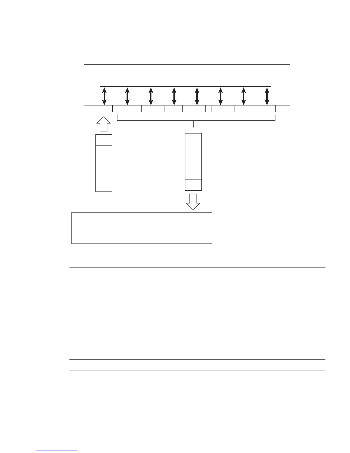
Figure 1 Default VLAN settings
802.1Q Switch
BLADEOS 6.5.2 Application Guide
VLAN 1
Port 1
PVID = 1
DA
SA
Incoming
untagged
packet
Key
By default:
Data
CRC
All ports are assigned PVID = 1
All ports are untagged members of VLAN 1
Port 2 Port 3 Port 4 Port 5
CRC
Outgoing
untagged packet
(unchanged)
Data
SA
DA
Port 6 ...
Port 7
BS45010A
Note – The port numbers specified in these illustrations may not directly correspond to the physical
port configuration of your switch model.
When a VLAN is configured, ports are added as members of the VLAN, and the po rts are defined as
either tagged or untagged (see Figure 2 through Figure 5).
The default configu rat ion settings for th e G81 24 has all ports set as u nt agg ed members of VLAN 1
with all ports configured as PVID = 1. In the default configuration example shown in Figure 1, all
incoming packets are assigned to VLAN 1 by the default port VLAN identifier (PVID =1).
Figure 2 through Figure 5 illustrate generic examples of VLAN tagging. In Figure 2, untagged
incoming packets are assigned directly to VLAN 2 (PVID = 2). Port 5 is configured as a tagged
member of VLAN 2, and port 7 is configured as an untagged member of VLAN 2.
Note – The port assignm ents in the following figures are not meant to match the G8124.
BMD00220, October 2010 Chapter 6: VLANs 91
Page 92
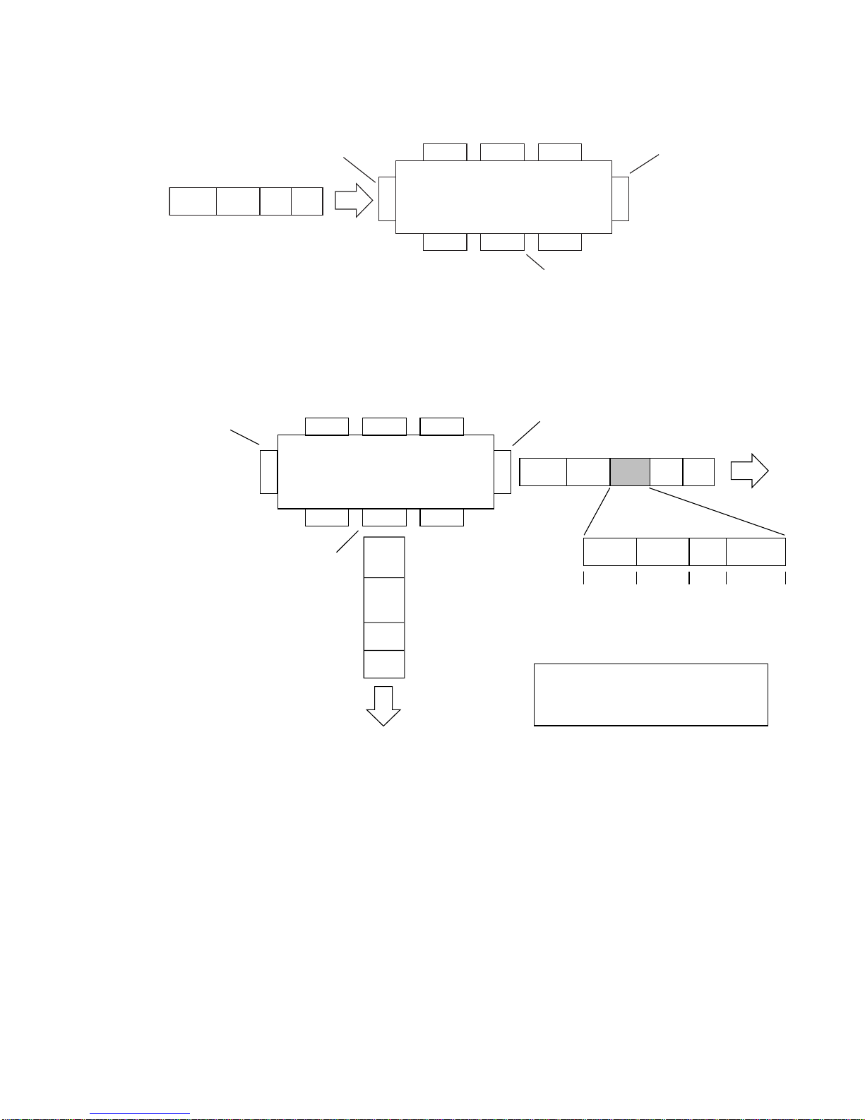
BLADEOS 6.5.2 Application Guide
Figure 2 Port-based VLAN assignment
PVID = 2
Untagge d pa c ke t
B
efore
Port 1
DASADataCRC
Port 4
Port 6
Port 2 Port 3
802.1Q S witch
Port 7 Port 8
Ta gged me mbe r
of V L A N 2
Port 5
Untagge d membe r
of V L A N 2
As shown in Figure 3, the untagged packet is marked (tagged) as it leaves the switch through port 5,
which is configured as a tagged member of V LAN 2. The untagged packe t remains unch anged as i t
leaves the switch through port 7, which is configured as an untagged member of VLAN 2.
Figure 3 802.1Q tagging (after port-based VLAN assignment)
PVID = 2
Port 1
Port 4
Port 6 Port 7 Port 8
Untagged memeber
of VLAN 2
Outgoing
untagged packet
(unchanged)
Port 2 Port 3
802.1Q Switch
CRC
Data
SA
DA
Tagged member
of VLAN 2
Port 5
(*Recalculated)
Key
Priority
CFI
VID
DASADataCRC* Tag
8100 CFI
16 bits 3 bits 1 bits 12 bits
After
- User_priority
- Canonical format indicator
- VLAN identifier
VID = 2Priority
In Figure 4, tagged incoming packets are assigned directly to VLAN 2 because of the tag
assignment in the packet. Port 5 is configured as a tagged member of VLAN 2, and port 7 is
configured as an untagged member of VLAN 2.
92 Chapter 6: VLANs BMD00220, October 2010
Page 93
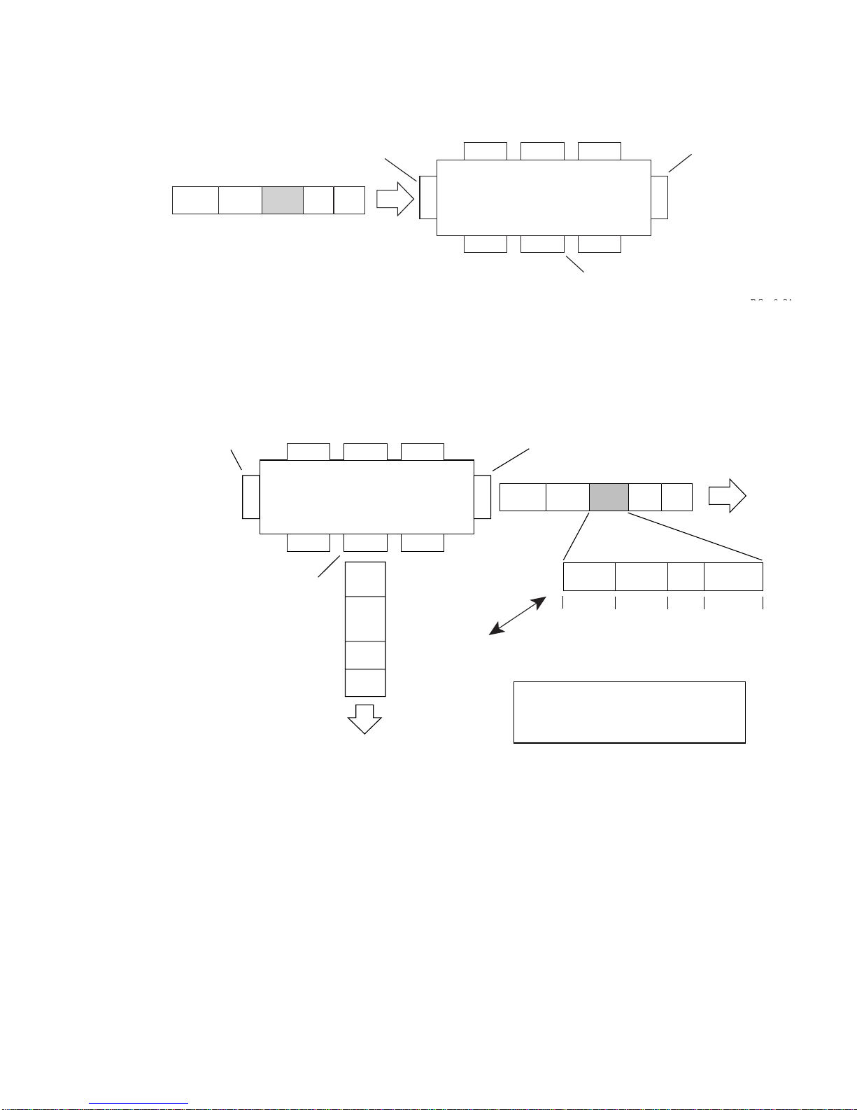
Figure 4 802.1Q tag assignment
BLADEOS 6.5.2 Application Guide
Ta gged pa c k et
B
efore
PVID = 2
DASATagDataCRC
Port 1
Port 4
Port 6
Port 2 Port 3
802.1Q S witch
Port 7 Port 8
Ta gged me mbe r
of V L A N 2
Port 5
Untagge d membe r
of V L A N 2
As shown in Figure 5, the tagged packet remains unchanged as it leaves the switch through port 5,
which is configured as a tagged member of VLAN 2. However, the tagged packet is stripped
(untagged) as it leaves the switch through port 7, which is configured as an untagged member of
VLAN 2.
Figure 5 802.1Q tagging (after 802.1Q tag assignment)
PVID = 2
Port 1
Port 4
Port 6 Port 7 Port 8
Port 2 Port 3
802.1Q Switch
Port 5
Tagged member
of VLAN 2
DASADataCRC Tag
Untagged member
of VLAN 2
CRC*
Data
SA
DA
(*Recalculated)
Outgoing
untagged packet
changed
(tag removed)
Key
Priority
CFI
VID
8100 CFI
16 bits 3 bits 1 bit 12 bits
After
- User_priority
- Canonical format indicator
- VLAN identifier
VID = 2Priority
BMD00220, October 2010 Chapter 6: VLANs 93
Page 94

BLADEOS 6.5.2 Application Guide
VLAN Topologies an d Design Considerations
By default, the G8124 software is configured so that tagging is disabled on all ports.
By default, the G8124 software is configured so that all data ports are members of VLAN 1.
By default, the BLADEOS software is configured so that the management ports (MGTA and
MGTB) are members of VLAN 4095 (the management VLAN).
STG 128 is reserved for switch management.
When using Spanning Tree, STG 2-128 may contain only one VLAN unless Multiple
Spanning-Tree Protocol (MSTP) mode is used. With MSTP mode, STG 1 to 32 can include
multiple VLANs.
VLAN Configuration Rules
VLANs operate according to specific configuration rules. When creating VLANs, consider the
following rules that determine how the configured VLAN reacts in any network topology:
All ports involved in trunking and port mirroring must have the same VLAN configuration. If
a port is on a trunk with a mirroring port, the VLAN configuration cannot be changed. For
more information trunk groups, see “Ports and Trunking” on page 101.
All ports that are involved in port mirroring must have memberships in the same VLANs. If a
port is configured for port mirroring, the port’s VLAN membership cannot be changed. For
more information on configuring port mirroring, see “Port Mirroring” on page 377.
94 Chapter 6: VLANs BMD00220, October 2010
Page 95
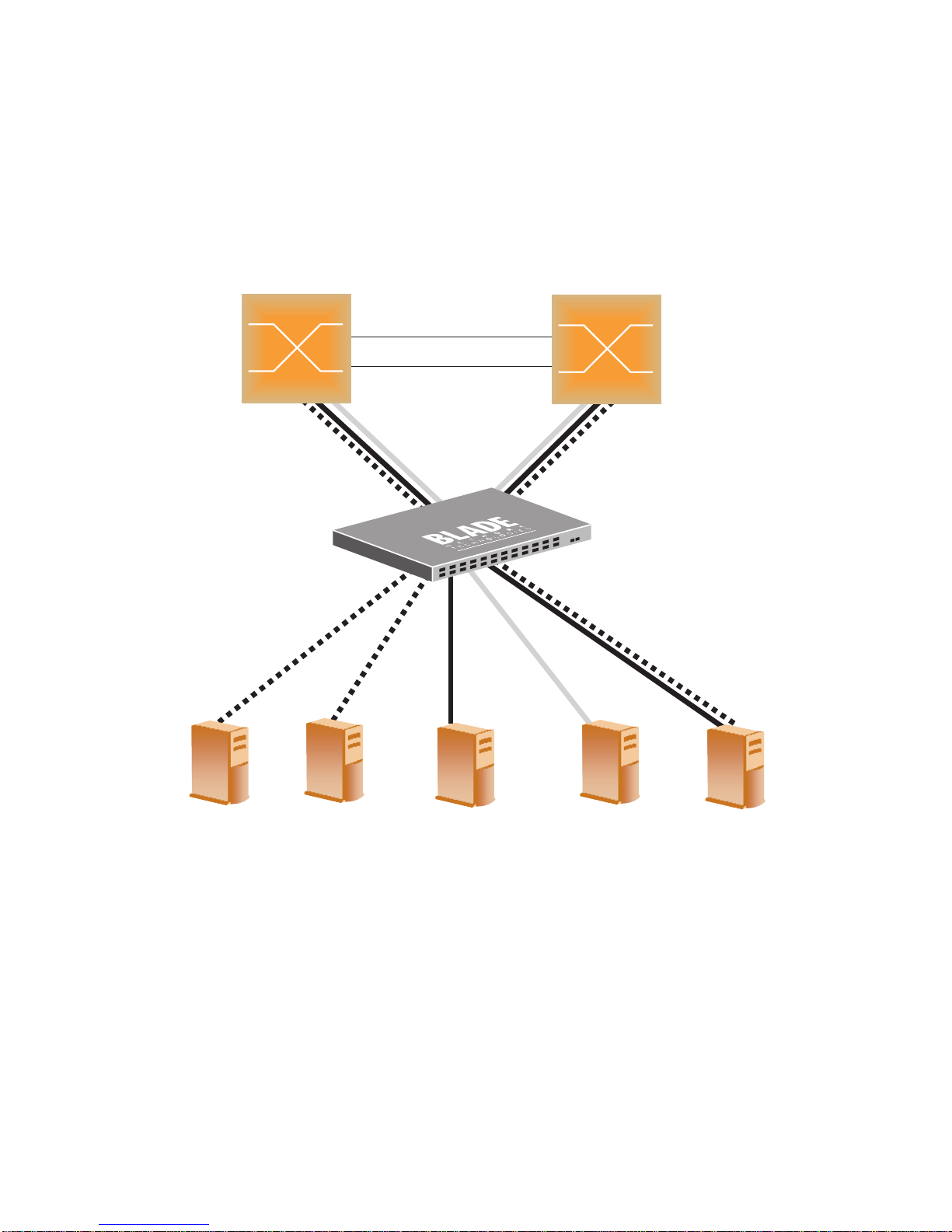
BLADEOS 6.5.2 Application Guide
Multiple VLANs with T agging Adapters
Figure 6 illustrates a network topology described in Note – and the configuration example on page
page 97.
Figure 6 Multiple VLANs with VLAN-Tagged Gigabit Adapters
Enterprise
Routing Switch
Enterprise
Routing Switch
Server 1
VLAN 1
BMD00220, October 2010 Chapter 6: VLANs 95
Server 2
VLAN 1
Server 3
VLAN 2
Server 4
VLAN 3
Server 5
VLAN 1, 2
Page 96

BLADEOS 6.5.2 Application Guide
The features of this VLAN are described below:
Component Description
G8124 switch This switch is configured with three VLANs that repr esent three dif ferent IP
Server 1 This server is a member of VLAN 1 and has presence in only one IP s ubn et.
Server 2 This server is a member of VLAN 1 and has presence in only one IP s ubn et.
Server 3 This server belongs to VLAN 2, and it is logically in the same IP subnet as
Table 6-1 Multiple VLANs Example
subnets. Five ports are connected downstream to servers. Two ports are
connected upstream to routing switches. Uplink ports are members of all
three VLANs, with VLAN tagging enabled.
The associated switch port is only a member of VLAN 1, so tagging is
disabled.
The associated switch port is only a member of VLAN 1, so tagging is
disabled.
Server 5. The associated switch port has tagging disabled.
Server 4 A member of VLAN 3, this server can communicate only with other servers
via a router. The associated switch port has tagging disabled.
Server 5 A member of VLAN 1 and VLAN 2, this server can communicate only with
Server 1, Server 2, and Server 3. The associated switch port has tagging
enabled.
Enterprise
Routing switches
These switches must have all three VLANs (VLAN 1, 2, 3) configured. They
can communicate with Server 1, Server 2, and Server 5 via VLAN 1. They
can communicate with Server 3 and Server 5 via VLAN 2. They can
communicate with Server 4 via VLAN 3. Tagging on switch ports is
enabled.
Note – VLAN tagging is requi red only on ports that are connected to other switches or on ports that
connect to tag-capable end-stations, such as servers with VLAN-tagging adapters.
96 Chapter 6: VLANs BMD00220, October 2010
Page 97

BLADEOS 6.5.2 Application Guide
VLAN Configuration Example
Use the following procedure to configure the example network shown in Figure 6.
1. Enable VLAN tagging on server ports that support multiple VLANs.
RS G8124(config)# interface port 5
RS G8124(config-if)# tagging
RS G8124(config-if)# exit
2. Enable tagging on uplink ports that support multiple VLANs.
RS G8124(config)# interface port 19
RS G8124(config-if)# tagging
RS G8124(config-if)# exit
RS G8124(config)# interface port 20
RS G8124(config-if)# tagging
RS G8124(config-if)# exit
3. Configure the VLANs and their member ports.
RS G8124(config)# vlan 2
RS G8124(config-vlan)# enable
RS G8124(config-vlan)# member 3
RS G8124(config-vlan)# member 5
RS G8124(config-vlan)# member 19
RS G8124(config-vlan)# member 20
RS G8124(config-vlan)# exit
RS G8124(config)# vlan 3
RS G8124(config-vlan)# enable
RS G8124(config-vlan)# member 4,19,20
RS G8124(config-vlan)# exit
By default, all ports are members of VLAN 1, so configure only those ports that belong to other
VLANs.
BMD00220, October 2010 Chapter 6: VLANs 97
Page 98

BLADEOS 6.5.2 Application Guide
Private VLANs
Private VLANs provide Layer 2 isolation between the ports within the same broadcast domain.
Private VLANs can control traffic within a VLAN domain, and provide port-b ased security for host
servers.
Use Private VLANs to partition a VLAN domain into sub-domains. Each sub-domain is comprised
of one primary VLAN and one or more secondary VLANs, as follows:
Primary VLAN—carries un idirectional tra ff ic down stream fro m promis cuous port s. Each Pri -
vate VLAN configurati on h as onl y one primary V LAN. Al l port s in t he Pr ivate VL AN are
members of the primary VLAN.
Secondary VLAN—Secondary VLANs are internal to a private VLAN domain, an d are defined
as follows:
Isolated VLAN—carries unidirectional traffic upstream from th e host servers towar d ports
in the primary VLAN and the gateway. Each Private VLAN configuration can contain only
one isolated VLAN.
Community VLAN—carries upstream traffic from ports in the community VLAN to other
ports in the same community, and to ports in the primary VLAN and the gateway. Each
Private VLAN configuration can contain multiple community VLANs.
After you define the primary VLAN and one or more secondary VLANs, you map the secondary
VLAN(s) to the primary VLAN.
Private VLAN Port s
Private VLAN ports are defined as follows:
Promiscuous—A promiscuous port is a port that belongs to the primary VLAN. The promis-
cuous port can communicate with all the interf aces, including p orts in the second ary VLANs
(Isolated VLAN and Community VLANs). Each promiscuous port can belong to only one Private VLAN.
Isolated—An isolated port is a host port that belon gs to an isolated VLAN. Each isolated port
has complete lay er 2 separation from ot her ports within the s ame private VLAN (incl uding other
isolated ports), except for the promiscuou s ports.
Traffic sent to an isolated port is blocked by the Private VLAN, except the traffic from
promiscuous ports.
Traffic received from an isolated port is forwarded only to promiscuous ports.
Community—A community port is a host port that belongs to a community VLAN. Community
ports can communicate with other ports in th e same community VLAN, and with pr omiscuous
ports. These interfaces are isolated at layer 2 fro m all other interfaces in o ther communities and
from isolated ports within the Private VLAN.
98 Chapter 6: VLANs BMD00220, October 2010
Page 99

BLADEOS 6.5.2 Application Guide
Configuration Guidelines
The following guidelines apply when configuring Private VLANs:
The default VLAN 1 c annot be a Pr ivate VLAN.
The management VLAN 4095 can not b e a Priv ate VLAN. The management port can not be a
member of a Private VLAN.
IGMP Snooping must be dis abled on i solated VLANs.
Each secondary port’s (isolated port and community ports) PVID mus t match its cor responding
secondary VLAN ID.
Ports within a second ary VLAN can not be members o f oth er VLANs.
All VLANs that comprise the Private VLAN must belong to the s ame Spanning T ree Group.
Configuration Example
Follow this procedure to configure a Private VLAN.
1. Select a VLAN and define the Private VLAN type as primary.
RS G8124(config)# vlan 100
RS G8124(config-vlan)# enable
RS G8124(config-vlan)# member 2
RS G8124(config-vlan)# private-vlan type primary
RS G8124(config-vlan)# private-vlan enable
RS G8124(config-vlan)# exit
2. Configure a secondary VLAN and map it to the primary VLAN.
RS G8124(config)# vlan 110
RS G8124(config-vlan)# enable
RS G8124(config-vlan)# member 3
RS G8124(config-vlan)# member 4
RS G8124(config-vlan)# private-vlan type isolated
RS G8124(config-vlan)# private-vlan map 100
RS G8124(config-vlan)# private-vlan enable
RS G8124(config-vlan)# exit
3. Verify the configuration.
RS G8124(config)# show private-vlan
Private-VLAN Type Mapped-To Status Ports
------------ --------- ---------- ---------- ----------------100 primary 110 ena 2
110 isolated 100 ena 3-4
BMD00220, October 2010 Chapter 6: VLANs 99
Page 100

BLADEOS 6.5.2 Application Guide
100 Chapter 6: VLANs BMD00220, October 2010
 Loading...