

Page 1
Instruction Manual
Manuel d’utilisation
RTF
Page 2
2
EN
• Always keep a safe distance in all directions around your model
to avoid collisions or injury. This model is controlled by a radio
signal subject to interference from many sources outside your
control. Interference can cause momentary loss of control.
• Always operate your model in open spaces away from
full-size vehicles, traffi c and people.
• Always carefully follow the directions and warnings for
this and any optional support equipment (chargers, rechargeable
battery packs, etc.).
• Always keep all chemicals, small parts and anything electrical
out of the reach of children.
• Always avoid water exposure to all equipment not
specifi cally designed and protected for this purpose.
Moisture causes damage to electronics.
• Never place any portion of the model in your mouth as it could
cause serious injury or even death.
• Never operate your model with low transmitter batteries.
• Always keep aircraft in sight and under control.
• Always move the throttle fully down at rotor strike.
• Always use fully charged batteries.
• Always keep transmitter powered on while aircraft is powered.
• Always remove batteries before disassembly.
• Always keep moving parts clean.
• Always keep parts dry.
• Always let parts cool after use before touching.
• Always remove batteries after use.
• Never operate aircraft with damaged wiring.
• Never touch moving parts.
Age Recommendation: Not for children under 14 years. This is not a toy.
WARNING: Read the ENTIRE instruction manual to become familiar with the features of the product before operating.
Failure to operate the product correctly can result in damage to the product, personal property and cause serious injury.
This is a sophisticated hobby product. It must be operated with caution and common sense and requires some basic
mechanical ability. Failure to operate this Product in a safe and responsible manner could result in injury or damage to the
product or other property. This product is not intended for use by children without direct adult supervision. Do not use with
incompatible components or alter this product in any way outside of the instructions provided by Horizon Hobby, LLC. This
manual contains instructions for safety, operation and maintenance. It is essential to read and follow all the instructions and
warnings in the manual, prior to assembly, setup or use, in order to operate correctly and avoid damage or serious injury.
The following terms are used throughout the product literature to indicate various levels of potential harm when operating
this product:
WARNING: Procedures, which if not properly followed, create the probability of property damage, collateral damage, and
serious injury OR create a high probability of superfi cial injury.
CAUTION: Procedures, which if not properly followed, create the probability of physical property damage AND a possibility
of serious injury.
NOTICE: Procedures, which if not properly followed, create a possibility of physical property damage AND a little or no
possibility of injury.
NOTICE
All instructions, warranties and other collateral documents are subject to change at the sole discretion of Horizon Hobby, LLC.
For up-to-date product literature, visit www.horizonhobby.com and click on the support tab for this product.
Meaning of Special Language
Safety Precautions and Warnings
If you are operating this product in North America, you are required to have an Amateur Radio (HAM) license. Visit
www.arrl.org for more information.
This product uses Betafl ight Third Party Software in portions of its coding. For more information on Betafl ight Software, please visit:
https://github.com/betafl ight/betafl ight/wiki.
THIRD PARTY SOFTWARE: This product may include code developed by one or more third parties (“Third Party Software”). Some
Third Party Software may be subject to other terms and conditions that may be available for download with the product documentation.
Notwithstanding the terms and conditions of this Agreement, the Third Party Software is licensed to you subject to the terms and conditions
of the software license agreement identifi ed in the open source software disclosure. If the third party terms and conditions include licenses
that provide for the availability of source code (such as the GNU General Public License), the open source software disclosure or the media
on which the software may be delivered will provide instructions where a copy of such source code can be obtained.
Page 3
3
EN
Table of Contents
Length
9.9 in (252mm)
Width
9.5 in (241mm)
Height
2.7 in (69mm)
Max Propeller Diameter
5 in (127mm)
Flying Weight
17.7 oz (502g)
Specifications
To receive product updates, special offers and more, register your product at www.horizonhobby.com.
NOTICE: Consult local laws and ordinances before operating FPV (fi rst person view) equipment. In some areas, FPV operation
may be limited or prohibited. You are responsible for operating this product in a legal and responsible manner.
As of this printing, you are required to register with the FAA if you own this product.
For up-to-date information on how to register with the FAA, please visit https://registermyuas.faa.gov/.
For additional assistance on regulations and guidance on UAS usage, visit knowbeforeyoufl y.org/.
First Flight Preparation ......................................................... 4
Flying Checklist ................................................................... 4
Charging Warnings............................................................... 4
Battery Charging .................................................................. 4
Installing the Transmitter Batteries ....................................... 5
Installing the Video Transmitter Antenna ............................... 5
Installing the Flight Battery .................................................. 5
Binding ................................................................................ 6
Transmitter Controls ............................................................ 6
Understanding the Primary Flight Controls ........................... 7
Flight Modes ........................................................................ 8
Flying the Vusion 250 ........................................................... 8
4.3 inch Video Monitor with DVR Features ............................ 9
Using the Video Monitor ....................................................... 9
Video Monitor FPV Goggle .................................................. 10
Video Transmitter ............................................................... 10
FPV Operation .................................................................... 11
Adding An External Spektrum™ Receiver .......................... 12
Installing the Propellers...................................................... 13
Replacing the Quadcopter Motor Arms ............................... 13
Post-Flight Inspection and Maintenance Checklist .............. 13
Troubleshooting Guide ....................................................... 14
Parts Explosion .................................................................. 15
Parts Listings ..................................................................... 15
Optional Parts .................................................................... 16
Limited Warranty ............................................................... 16
Warranty and Service Contact Information ......................... 17
FCC Information ................................................................. 17
IC Information .................................................................... 17
Compliance Information for the European Union ................. 17
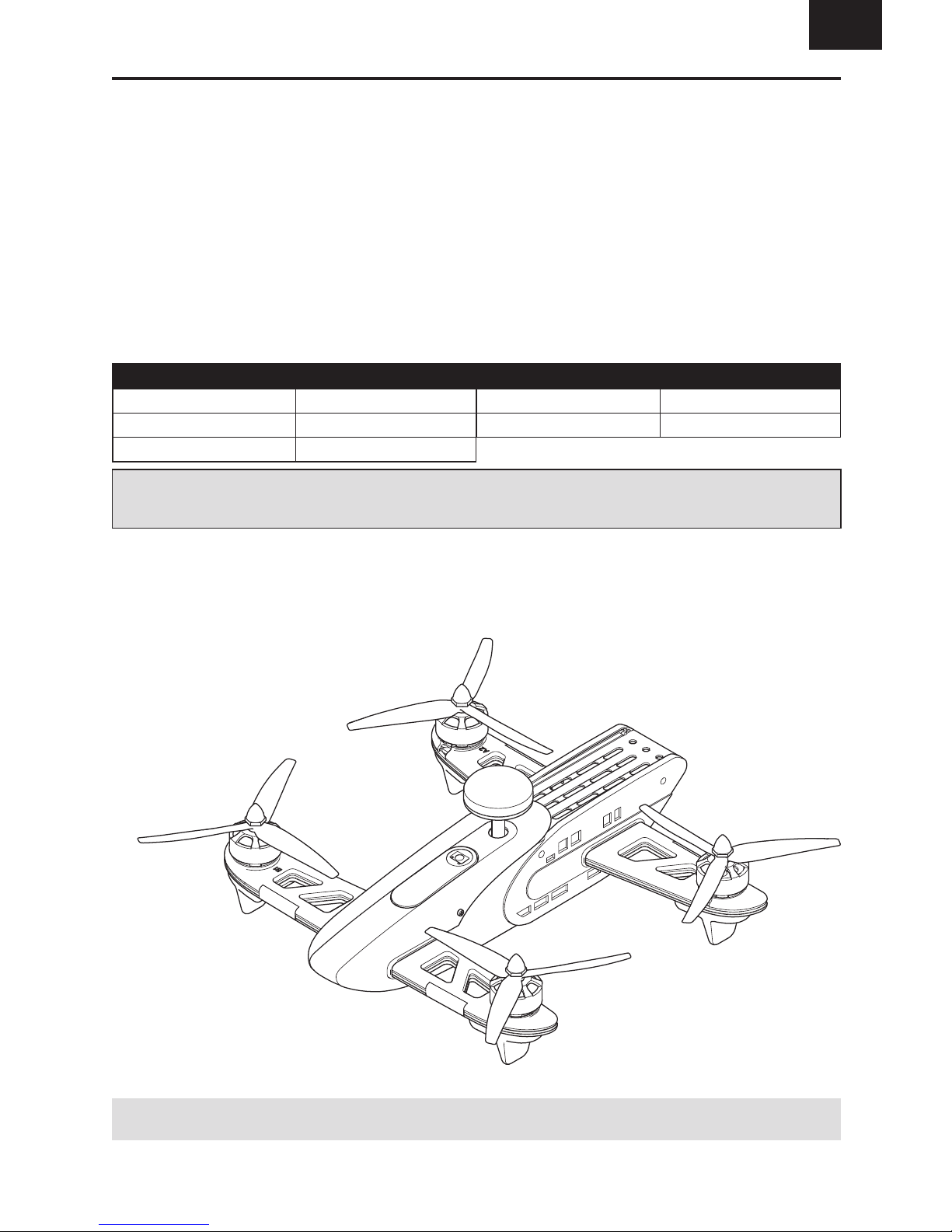
Box Contents:
• Vusion™ 250 FPV Racer Quadcopter
- Flight Controller (BLH02408)
- VTX Camera 25/200mW Vusion V2 (BLH02417)
- Omni Antenna Black R-SMA (BLH02420)
• LiPo 3S 11.1V 1500mAh (BLH02402)
• FPV-RM2 4.3” Monitor 5.8GHz 40 channel (TACZ5153)
• Video Monitor FPV Goggle (TACZ5200)
• Monitor Sunshield (TACZ5600)
• 6 channel Transmitter (RISJ2000)
• 2S/3S A/C Balance Charger
• 4 - AA Batteries
• Monitor Charge Cord
• Extra Set of Props
• Screwdriver
Page 4
4
EN
CAUTION: All instructions and warnings must be
followed exactly. Mishandling of Li-Po batteries can
result in a fi re, personal injury and/or property damage.
• NEVER LEAVE CHARGING BATTERIES UNATTENDED.
• NEVER CHARGE BATTERIES OVERNIGHT.
• By handling, charging or using the included Li-Po battery,
you assume all risks associated with lithium batteries.
• If at any time the battery begins to balloon or swell,
discontinue use immediately. If charging or discharging,
discontinue and disconnect. Continuing to use, charge
or discharge a battery that is ballooning or swelling can
result in fi re.
• Always store the battery at room temperature in a dry
area for best results.
• Always transport or temporarily store the battery in a
temperature range of 40–120º F (5–49° C).
• Do not store battery or model in a car or direct sunlight.
If stored in a hot car, the battery can be damaged or even
catch fi re.
• Always charge batteries away from fl ammable materials.
• Always inspect the battery before charging.
• Always disconnect the battery after charging, and
let the charger cool between charges.
• Always constantly monitor the temperature of the
battery pack while charging.
• ONLY USE A CHARGER SPECIFICALLY DESIGNED TO
CHARGE LI-PO BATTERIES. Failure to charge the battery
with a compatible charger may cause a fi re resulting in
personal injury and/or property damage.
• Never discharge Li-Po cells to below 3V under load.
• Never cover warning labels with hook and loop strips.
• Never charge batteries outside recommended levels.
• Never charge damaged batteries.
• Never attempt to dismantle or alter the charger.
• Never allow minors to charge battery packs.
• Never charge batteries in extremely hot or cold places
(recommended between 40–120° F or (5–49° C) or place
in direct sunlight.
Charging Warnings
Battery Charging
First Flight Preparation
• Remove and inspect contents
• Begin charging the fl ight battery
• Install the transmitter batteries
• Install the video transmitter antenna
• Install the fl ight battery in the aircraft
(once it has been fully charged)
• Bind your transmitter
• Familiarize yourself with the controls
• Find a suitable area for fl ying
Flying Checklist
❏ Always turn the transmitter on fi rst
❏ Plug the fl ight battery into the lead from the fl ight control board
❏ Allow the aircraft to initialize and arm properly
❏ Fly the aircraft
❏ Land the aircraft
❏ Unplug the fl ight battery from the fl ight control board
❏ Always turn the transmitter off last
The Vusion 250 quadcopter operates with a 3-cell (3S), 11.1V
LiPo battery. The included charger is capable of charging 2 or
3S LiPo batteries.
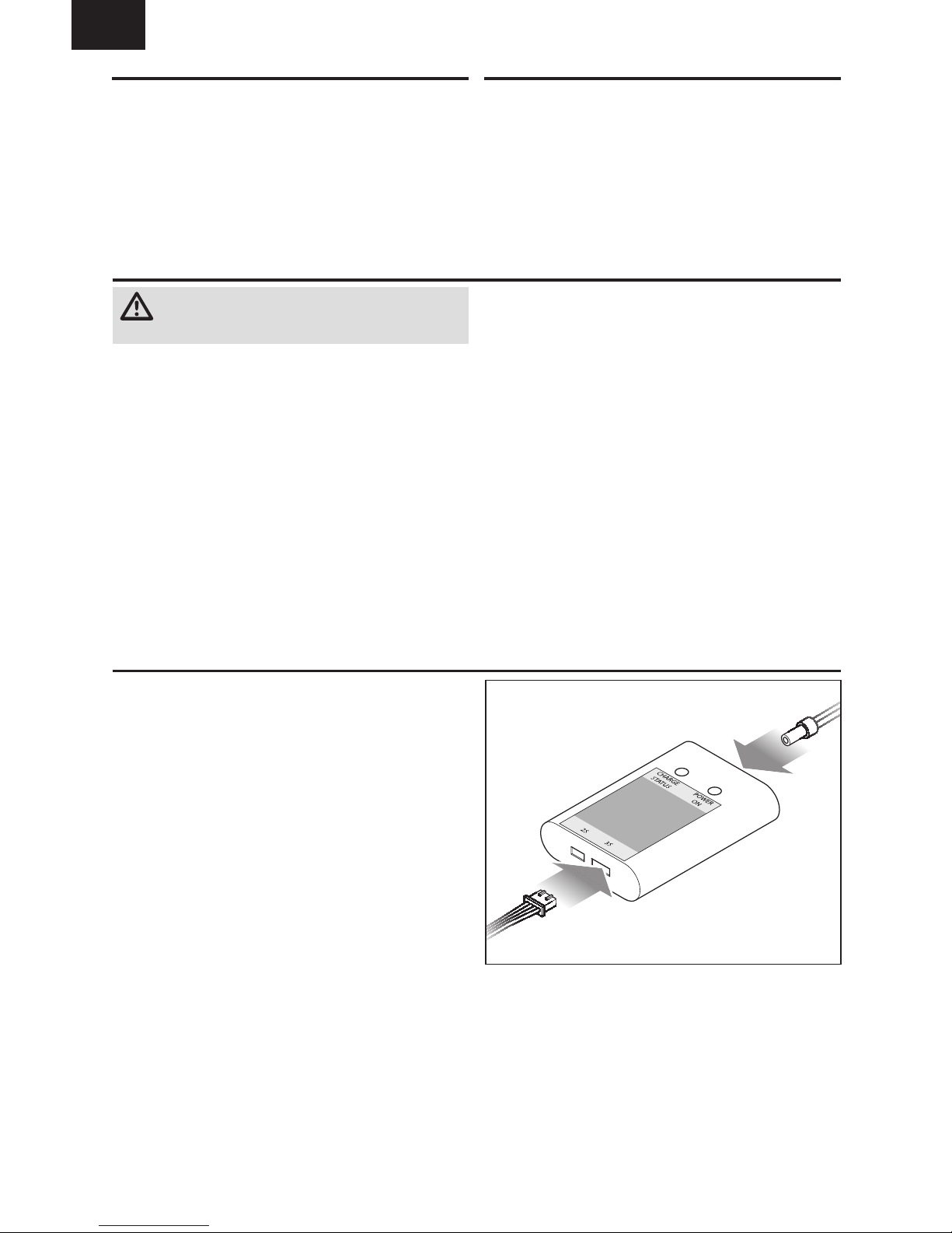
To charge the included 3S LiPo battery:
1. Connect the AC power adapter to the charger.
2. Connect the AC adapter to 120V outlet.
3. Insert the fl ight battery balance connector to the 3S
balance port on the charger. The charger will begin
charging.
4. Disconnect the battery from the charger when the
charging process is complete.
LED indicators:
Power LED, Solid Red: Power ON
Charge LED, Solid Red: Charging
Charge LED, Solid Green: Charge Complete
Charge LED, Flashing Red: Error
Page 5
5
EN
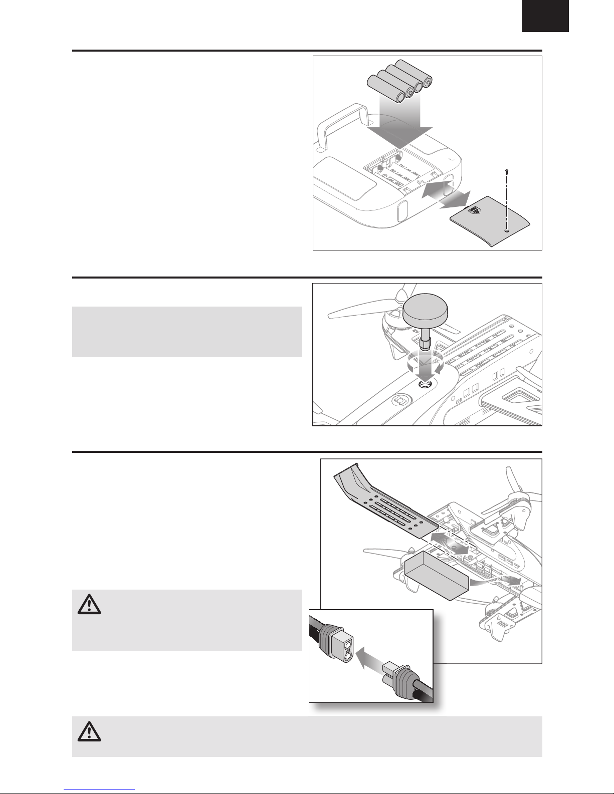
Installing the Transmitter Batteries
Installing the Video Transmitter Antenna
Installing the Flight Battery
CAUTION: Always disconnect the Li-Po battery from the quadcopter when not fl ying to avoid over-discharging the
battery. Batteries discharged to a voltage lower than the lowest approved voltage may become damaged, resulting
in loss of performance and potential fi re when batteries are charged.
1. Remove the battery door screw.
2. Slide the battery door down to open.
3. Install 4 AA alkaline batteries in the transmitter.
4. Re-install the battery door and battery door screw.
Replace the transmitter batteries when the transmitter
indicates low voltage. The right LED fl ashes and the
transmitter beeps when the battery voltage is low.
Install the video transmitter antenna in the top of the
quadcopter as shown.
NOTICE: Never install the fl ight battery or power on
the quadcopter without the video transmitter antenna
installed. Doing so, even for a short time, will damage the
video transmitter.
1. Remove the battery compartment cover by pulling on the
edge of the cover to unsnap it from the frame.
2. Slide the fl ight battery into the quadcopter frame and
re-install the cover.
3. Lower the throttle to the lowest position.
4. Power on the transmitter.
IMPORTANT: Always power the transmitter on before
powering on the aircraft.
5. Connect the battery cable to the aircraft power lead,
noting correct polarity. Do not move the quadcopter until
the receiver initializes.
CAUTION: Connecting the battery to the aircraft
power lead with reversed polarity will cause
damage to the power distribution board, ESCs and the
battery. Damage caused by incorrectly connecting the
battery is not covered under warranty.
6. The quadcopter motors will beep once and the receiver
status LED will glow solid red.
IMPORTANT: If the receiver status LED fl ashes red, the
transmitter is not bound to the aircraft. See the Binding
section to re-bind the aircraft to the transmitter.
Page 6
6
EN
Binding
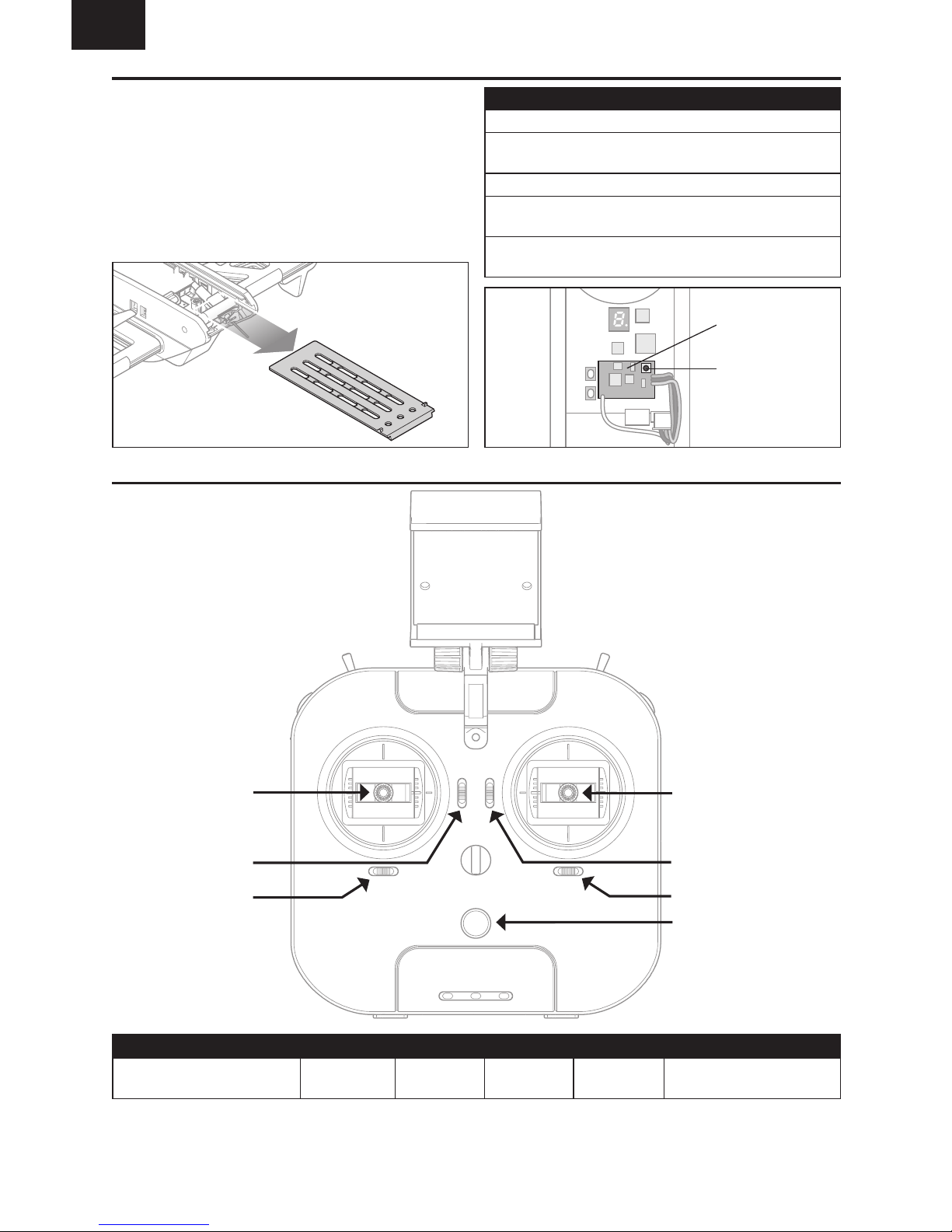
Transmitter Controls
ABCDEF
Aileron (Roll) (Left/Right)
Elevator (Pitch) (Up/Down)
Elevator Trim Aileron Trim Rudder Trim Throttle Trim
Rudder (Yaw) (Left/Right)
Throttle (Up/Down)
Dual Rate Switch
A
B
C
D
E
F
On/Off Switch
LEDs
Flight Mode Switch
Bind Button
LED
Monitor Cradle
Binding Procedure
1. Power off your transmitter.
2. Remove the upper rear cover of the aircraft. Press down on
the rear edge of the cover and pull the cover out of the frame.
3. Power on the aircraft.
4. Press and hold the bind button until the red LED on the
control board ashes rapidly.
5. Power on the transmitter. The LED on the control board
glows solid to show the bind was successful.
The transmitter included with this aircraft is pre-bound to the
receiver at the factory. If it becomes necessary to re-bind the
transmitter to the receiver, indicated by a red receiver status
LED, follow the procedure given in the table.
If you encounter problems, obey the binding instructions and refer
to the troubleshooting guide for further instructions. If necessary,
contact the appropriate Horizon Hobby product support offi ce.
Failsafe/Beacon
The quadcopter will autoland and start beeping if the signal
from the transmitter is lost. This feature can be used as a
beacon to help locate the quadcopter, if it has crashed, by
turning off the transmitter and listening for the beeping of
the aircraft.
Page 7

7
EN
Rudder
Rudder left
Rudder right
Understanding the Primary Flight Controls
If you are not familiar with the controls of your quadcopter, take a few minutes to familiarize yourself with them before
attempting your fi rst fl ight.
Throttle
Throttle downThrottle up
Left Side View Left Side View
Descend
Climb
Nose Yaws Left Nose Yaws Right
Elevator
Forward
Elevator down
Elevator up
Backward
Left Side View Left Side View
Aileron
Aileron left
Left
Aileron right
Right
Rear ViewRear View
Page 8

8
EN
Flying the Vusion 250
Flight Modes
Motor Arming
Turn on the transmitter. Connect the fl ight battery to the
aircraft. Place the quadcopter on a level surface and let it sit
for 10seconds to let the fl ight controller set up the gyros.
Set the dual rate switch to high. The motors will not arm if
the dual rate switch is in the low position. With the throttle at
its lowest setting, hold the yaw control (left stick) to the right.
The quadcopter will beep once to indicate the motors are
armed. Advance the throttle to start the motors spinning.
CAUTION: Any throttle input while the motors are
armed will cause the motors to spin. Always keep
body parts, clothing and loose items away from the propellers.
To disarm the motors, lower the throttle to the lowest setting.
Set the dual rate switch to high. Hold the yaw control to the
left until the quadcopter beeps, indicating the motors are
disarmed. The motors will also disarm if the throttle is at its
lowest setting for more than 5seconds.
Takeoff
With the motors armed and spinning, advance the throttle
slowly to take off. Increase the throttle until the model is
approximately 2ft.(600mm) off the ground and check the
trim so the model fl ies as desired. Once the trim is adjusted,
begin fl ying the model.
Flight times for the included battery will vary according to
how aggressively the throttle is used.
Low Voltage Cutoff (LVC)
LVC decreases the power to the motors when the battery
voltage gets low. When the motor power decreases, land the
aircraft immediately and recharge the fl ight battery.
LVC does not prevent the battery from over-discharge during
storage.
NOTICE: Repeated fl ying to LVC will damage the battery.
Landing
To land, hover the aircraft over the landing spot and slowly
reduce the throttle. When the aircraft touches down, lower
the throttle fully.
To disarm the motors, lower the throttle to the lowest setting.
Set the dual rate switch to high. Hold the yaw control to the
left until the quadcopter beeps, indicating the motors are
disarmed. The motors will also disarm if the throttle is at its
lowest setting for more than 5seconds.
Unplug and remove the battery.
The quadcopter has 3 fl ight modes accessible by changing
the fl ight mode switch position.
Angle Mode: This mode has auto level, mild roll rates and
very limited tilt angles. Ideal for the pilot who is moving up
from an entry level quadcopter.
Horizon Mode: This mode still has auto level, but has
higher roll rates and a high tilt angle setting. This mode is
for more experienced pilots.
Acro Mode: This mode has no limits on tilt and faster roll
rates. The quad will not auto level in this mode. This mode
offers the most maneuverability but requires the pilot to be
able to control the attitude of the quadcopter.
It normally takes a week or two of practice to learn to fl y
consistently in Acro Mode. Start by fl ying line of sight (noFPV)
until you can comfortably control the quad. If possible, fl y
in an open area over tall grass to minimize damage to the
aircraft when you crash. When you are comfortable making a
fl ip in this mode, you should be ready for FPV.
Flight Modes
Switch
Position
Stability
Mode
Tilt
Angle
Roll
Rate
Angle Mode Farthest Stability 30 Low
Horizon Mode Middle Stability 45 Medium
Acro Mode Closest Rate Unlimited High
Page 9

9
EN
4.3 inch Video Monitor with DVR Features
5.8GHz Antenna connector
Menu Buttons:
Press and hold the M button
to change to playback mode
Single push the M button to select options:
Brightness Contrast
Color Language
Backlight Reset
Use the and buttons to modify the
selected option
Micro Memory Card Slot
Channel Selection Button
Single push to change channel
Band Button
Single push to change band
Press and hold for frequency scan
5V Micro USB Charge Port
Charge Status LED
Red = charging
Off = charged
Power Switch
DVR Start/Stop Button
Band Channel
Clip Timer Total Time
Frequency Battery Level
* The video transmitter on the quadcopter does not operate in the E band.
Monitor Band FPV Band
AA
BB
CE*
D FS/IRC
E Race
CAUTION: Do not power on the monitor without
the antenna attached. Doing so will damage the
video receiver amplifi ers. Amplifi er damage is not covered
by warranty.
1. Before using the 4.3 inch video monitor, make sure
the monitor is fully charged. Connect the micro USB
connector to a 5V USB power source. The charge indicator
LED will glow red while charging and will go off when the
monitor is fully charged.
2. Open the sun shade, if installed.
3. Insert a micro memory card (not included) in the slot on
the side of the video monitor. Press the card in until it
locks. To remove the card, press in slightly and release
until the card is released. Always insert the memory card
before powering on the video monitor.
4. Power on the video monitor and look for a clear channel.
Clear channels will have a consistent static background.
Channels with interference will display horizontal static
lines. Select one of the clear channels.
5. Once you have chosen a clear channel on the monitor,
select the same channel on the video transmitter.
6. Place the monitor in the transmitter cradle or in the
goggle mount.
Using the Video Monitor
Page 10

10
EN
Band
CH 1 CH 2 CH 3 CH 4 CH 5 CH 6 CH 7 CH 8
Band A
5865 5845 5825 5805 5785 5765 5745 5725
Band B
5733 5752 5771 5790 5809 5828 5847 5866
FS/IRC
5740 5760 5780 5800 5820 5840 5860 5880
RaceBand
5658 5695 5732 5769 5806 5843 5880 5917
Available Frequencies, (mHz):
LCD display
Output power
button
Band/channel
button
Field of view lever
Video Transmitter
The Vusion 250 quadcopter comes equipped with a selectable
output (25mW or 200mW), 32 channel video transmitter
installed. The VTX is capable of transmitting on A, B, FS/IRC
and Race bands. The video transmitter includes a digital
display which continuously scrolls through the active band and
channel. Press down and pull on the rear of the top cover for
access to the video transmitter.
To change the video transmitter ouptut power level:
1. Press and hold band/channel button.
2. When the channel fl ashes on the LCD screen, press and
hold the output power button.
3. Release the buttons when the output symbol, – or =,
appears.
4. Press the band/channel button to change output level.
The following symbols indicate the selected output:
“–” = 25mW.
“=” = 200mW.
5. After 5 seconds of release channel/power selection will
auto exit.
To change the band:
1. Press and hold the band/channel button until the active
band continuously fl ashes in the display.
2. Press and release the band/channel button to scroll
through the available bands.
3. Wait approximately 5seconds until the digital display
shows the band followed by the channel.
To change the active channel:
Press and release the band/channel button to scroll through
the available channels within the active band.
Video Monitor FPV Goggle
The FPV Goggle is designed to hold the included video
monitor for a more immersive view from the FPV camera.
The goggle can also be used with mobile devices that are
less than 5.9 x 3.15 inches to watch videos. The goggle is
large enough that reading glasses can be used if needed to
sharpen the image from the monitor.
To install the video monitor in the goggle:
1. Remove the sunshade from the video monitor, if installed.
2. Pull on the goggle cover tab to open the goggle cover.
3. Place the monitor or mobile device in the compartment
and close the goggle cover.
Pulling the fi eld of view lever on top of the goggle closer to
your eyes will slightly expand the fi eld of view for use with
devices that have a larger screen.
The length of the straps can be adjusted by moving the hook
and loop pad at the end of each strap.
A small adhesive backed foam pad is included to use to
secure a thin mobile device (less than 3/8”). The pad should
be mounted in the center of the goggle cover. Do not use the
pad with the included video monitor, the magnetic catch on
the cover may not close securely.
Page 11

11
EN
Consult local laws and ordinances before operating FPV
equipment. In some areas, FPV operation may be limited or
prohibited. You are responsible for operating this product in a
legal and responsible manner.
Flying FPV is more diffi cult than line of sight, because it is
diffi cult to determine altitude with just the camera view.
Practice in an open area with a spotter. If possible, fl y over
tall grass to minimize damage if you crash. When you are
comfortable fl ying in an open area, practice fl ying a pre-set
course. This will help you learn to corner faster.
The quadcopter has a built in camera and 32 channel VTX
that transmits on A, B, F and Race bands. The included
monitor must be set to the correct band and channel to
display the feed from the camera.
Before powering on the quadcopter, always scan the
available video frequencies, using the included video monitor,
to fi nd an open channel.
CAUTION: Do not power on the quadcopter while
others are fl ying FPV around you without fi rst knowing
what band and channel both you and any other pilots are
transmitting on. It is possible to swamp other nearby video
transmitters, causing others to lose video feed and crash.
To scan all available frequencies:
1. Attach the antenna to the FPV monitor and power the
monitor on.
2. Hold button B on the monitor for 2seconds and release
it. The monitor will scan all bands and channels and lock
onto any currently occupied channel.
3. Press and release button B to change bands.
IMPORTANT: The video monitor displays A, B, E, F and
Race bands. The quadcopter video transmitter does not
operate in the E band.
4. Press button CH to change to an unoccupied channel.
When an unoccupied video frequency is located, change the
video band and channel on the quadcopter to match the monitor.
To change the quadcopter video frequency:
1. Remove the rear top cover of the quadcopter.
2. Raise the camera by pushing down on the camera icon on
the top of the quadcopter.
3. Power on the fl ight control transmitter.
4. Power on the aircraft and allow it to initialize. The digital
display repeatedly shows the current band followed by
the channel.
5. Press and hold the band/channel button until the digital
display fl ashes the current band continuously.
6. Press and release the band/channel button to change to
the desired band.
7. Wait approximately 5seconds until the digital display
shows the band followed by the channel.
8. Press and release the band/channel button to change to
the desired channel. Confi rm the video feed is clear in the
monitor. Repeat steps 5-8 to fi nd a different channel if the
video is not clear.
9. Place the monitor in the cradle on the transmitter or
inside the goggle frame and replace the rear top cover of
the quadcopter.
FPV Operation
Page 12

12
EN
WARNING: Remove the propellers from the motors prior to performing any maintenance or changing any radio
components. Failure to do so may cause serious injury if the motors start unexpectedly.
Model Type
ACRO
F-Mode Setup
Switch 1 B
Switch 2 H
Channel Assign
Channel Input Confi g
1 Throttle Throttle
2 Aileron Aileron
3 Elevator Elevator
4 Rudder Rudder
5 Gear B
6 Aux 1 H
Frame Rate
22ms
DSMX
Servo Setup
Channel Travel Reverse
Throttle 150/150 Normal
Aileron 150/150 Reverse
Elevator 150/150 Normal
Rudder 150/150 Reverse
Gear 100/100 Normal
Aux1 100/100 Normal
D/R & Expo
Channel Sw Pos D/R Expo
Aileron
0 100/100 20%
1 100/100 20%
2 100/100 20%
Elevator
0 100/100 20%
1 100/100 20%
2 100/100 20%
Rudder
0 100/100 20%
1 100/100 20%
2 100/100 20%
Timer
Mode Count Down
Time 6:00
Start Throttle Out
Over 25%
One Time Inhibit
SETUP LIST FUNCTION LIST
Spektrum Transmitter Setup
Adding An External Spektrum™ Receiver
The Blade® Vusion™ quadcopter is compatible with the
Spektrum™ DSMX® quad race serial receiver (SPM4648).
After connecting the receiver, you must change the active
receiver on the fl ight controller using Betafl ight Confi gurator
software, available at
https://github.com/betafl ight
.
To install a remote receiver:
1. Remove the top rear cover by pressing down on the rear
edge and pulling the cover out of the frame.
2. Disconnect the stock receiver from the fl ight control board.
3. Connect the Spektrum DSMX receiver connector to the
fl ight control board as shown.
4. Secure the receiver in the frame.
5. Re-install the rear cover.
6. Load Betafl ight Confi gurator.
7. Connect the quadcopter to the computer using the micro
USB port.
8. Select “Receiver” from the Confi gurator menu.
9. Under “Channel Map” select “TAER 1234”.
10. Select “Confi guration” from the Confi gurator menu.
11. Under “Serial Receiver Provider” select receiver
“SPEKTRUM2048” .
Switch Functions:
Switch B: Flight Mode
Pos 0: Angle Mode
Pos 1: Horizon Mode
Pos 2: Acro Mode
Switch H: Motor Arm/Disarm
Pos 0: Disarmed
Pos 1: Armed
To arm the motors, lower the throttle fully and move switch
H to position 1.
Stock
receiver
connector
Spektrum
receiver
connector
Page 13

13
EN
CW
CW
CCW
CCW
2
1
3
4
4
1
2
3
Post-Flight Inspection and Maintenance Checklist
√
Cleaning
Make sure the battery is disconnected before cleaning. Remove dust and debris with a soft brush or a dry,
lint-free cloth.
Motors Replace the motor when the model will not fl y steady or veers off when doing a climb out.
Wiring Make sure the wiring does not block moving parts. Replace damaged wiring and loose connectors.
Fasteners
Make sure there are no loose screws, other fasteners or connectors. Do not over-tighten metal screws in plastic
parts. Tighten screws so the parts are mated together, then turn the screw only 1/8th of a turn more. Do not use
threadlock on or near plastic parts.
Propellers
Make sure there is no damage to the propellers or other parts that move at high speed. Damage to these parts
includes cracks, burrs, chips or scratches. Replace damaged parts before fl ying.
WARNING: Remove the propellers from the motors prior to performing any troubleshooting or maintenance.
Failure to do so may cause serious injury if the motors start unexpectedly.
Installing the Propellers
Replacing the Quadcopter Motor Arms
Refer to the illustration for the proper motor rotation and
propeller location.
The propellers have “CW” or “CCW” marked on the blades
to show proper location and rotation. Match the propeller
location to the illustration.
Secure the propellers using the propeller nuts.
Do not overtighten the nuts as damage to the propellers or
motors may result.
IMPORTANT: The motor shafts and nuts at the “CW”
propeller locations are reverse threads.
To replace the front motor arms:
1. Remove the video antenna.
2. Remove the four screws from the canopy and slide the
canopy from the front of the quadcopter.
3. Remove the two screws from each of the motor arms.
4. Pull the arms from the side of the quadcopter frame.
5. Reverse the process for re-assembly.
To replace the rear motor arms:
1. Remove the battery compartment cover.
2. Remove the two screws from each of the motor arms.
3. Pull the arms from the side of the quadcopter frame.
4. Reverse the process for re-assembly.
Page 14

14
EN
Troubleshooting Guide
WARNING: Remove the propellers from the motors prior to performing any troubleshooting or maintenance.
Failure to do so may cause serious injury if the motors start unexpectedly.
Problem Possible Cause Solution
Quadcopter control response is
inconsistent or requires extra
trim to neutralize movement
Quadcopter not initialized on a level surface
Disconnect the flight battery, center the control trim and
re-initialize the quadcopter
Battery not correctly placed
Adjust battery position so quadcopter balances in the
center of the frame
Quadcopter will not respond
to throttle
Throttle too high and/or throttle trim is too high
Reset controls with the throttle stick and throttle trim at the
lowest setting
Quadcopter moved during initialization
Disconnect the flight battery and re-initialize the
quadcopter while keeping the quadcopter from moving
Throttle channel is reversed
Disconnect flight battery, reverse the throttle channel on
the transmitter, recconnect flight battery
Travel adjust settings not correct
Refer to the transmitter setup table for correct travel adjust
settings.
Quadcopter does not function
and smells burnt after
connecting the fl ight battery
Flight battery connected with the wrong polarity
Replace the power distribution board. Connect the flight
battery noting proper polarity
Quadcopter has
reduced fl ight time or is
underpowered
Flight battery charge is low Completely recharge the flight battery
Inadequate power to flight battery charger Use a different power source for the charger
Flight battery is damaged
Replace the flight battery and follow the flight battery
instructions
Flight conditions might be too cold
Make sure the battery is warm (room temperature) before
use
Crashes immediately upon
lift-off
Propellers in wrong locations or incorrect flight
mode selected
Ensure propeller direction and motor direction are correct
Diffi culty binding
Bind button not pressed while
powering on the quadcopter
Power off quadcopter and repeat bind process
Transmitter too near aircraft during binding
process
Power off the transmitter. Move the transmitter a larger
distance from the aircraft or shield the aircraft from the
transmitter using your body. Disconnect and reconnect
the flight battery to the quadcopter. Follow the binding
instructions
Quadcopter or transmitter is too close to
large metal object, wireless source or another
transmitter
Move quadcopter and transmitter to another location and
attempt binding again
Diffi culty connecting
(after binding)
Transmitter not powered on before the
quadcopter
Power the quadcopter off. Power on the transmitter first
and then the quadcopter
Less than a 5-second wait between first
powering on the transmitter and connecting the
flight battery to the quadcopter
Leave the transmitter powered on. Disconnect and
reconnect the flight battery to the quadcopter
Flight battery or transmitter battery charge is
too low
Replace or recharge batteries
Quadcopter or transmitter is too close to
large metal object, wireless source or another
transmitter
Move quadcopter and transmitter to another location and
attempt connecting again
Static in FPV feed
Interference on chosen channel Change the video transmitter and receiver channel
Flying too close to 5.8 GHz WiFi source Remove WiFi source or move to a different flying area
Page 15

15
EN
1
25
20
24
2
4
6
3
5
19
21
21
19
19
19
24
7
17
18
16
14
12
12
13
13
15
15
14
23
24
8
10
Parts Explosion
Parts Listings
Part # Description
1
BLH02401
Canopy Vusion V2 Racer
2
BLH02402
LiPo 3S 11.1V 35C 1500mAh iC3
3
BLH02404
R/F Arm CCW 1806 Motor ESC V2
4
BLH02405
L/F Arm CW 1806 Motor ESC V2
5
BLH02406
R/R Arm CW 1806 Motor ESC V2
6
BLH02407
L/R Arm CCW 1806 Motor ESC V2
7
BLH02408
FC Board Module Set Vusion V2
8
BLH02411
L/F Arm Top, Bottom Vusion V2
9
BLH02412
R/F Arm Top, Bottom Vusion V2
10
BLH02413
L/R Arm Top, Bottom Vusion V2
11
BLH02414
R/R Arm Top, Bottom Vusion V2
12
BLH02415
Frame Left, Right Vusion V2
13
BLH02417
VTX Camera 25/200mW Vusion V2
14
BLH02418
Arm Receptacles Vusion V2
15
BLH02419
Camera VTX Case Vusion V2
Part # Description
16
BLH02420
Omni Antenna Black R-SMA
17
RISE2001
Top Cover Vusion 250 Race Quad
18
RISE2002
Battery Cover Vusion 250 Race Quad
19
RISE2008
Landing Gear Vusion 250 Race Quad
20
RISE2009
Prop Nuts CW/CCW Vusion 250 Race Quad
21
RISE2016
LED Arm Covers Vusion 250 Race Quad
22
RISE2025
Flight Control Board Dampers Vusion
23
RISE2026
Motor Shields Vusion 250 Race Quad
24
BLHA1004GR
5x4 FPV Race Prop Set, Green
25
BLHA1004BK
5x4 FPV Race Prop Set, Black
RISE2021
Screw Set Vusion 250 Race Quad
RISJ2000
Transmitter, 6-Channel Vusion 250
TACZ5153
FPV-RM2 4.3” Monitor 5.8GHz 40 channel
TACZ5200
FPV-G1 Goggles without Monitor
Page 16

16
EN
Limited Warranty
What this Warranty Covers
Horizon Hobby, LLC, (Horizon) warrants to the original purchaser that the
product purchased (the “Product”) will be free from defects in materials
and workmanship at the date of purchase.
What is Not Covered
This warranty is not transferable and does not cover (i) cosmetic damage,
(ii) damage due to acts of God, accident, misuse, abuse, negligence,
commercial use, or due to improper use, installation, operation or
maintenance, (iii) modification of or to any part of the Product, (iv)
attempted service by anyone other than a Horizon Hobby authorized
service center, (v) Product not purchased from an authorized Horizon
dealer, (vi) Product not compliant with applicable technical regulations, or
(vii) use that violates any applicable laws, rules, or regulations.
OTHER THAN THE EXPRESS WARRANTY ABOVE, HORIZON MAKES NO
OTHER WARRANTY OR REPRESENTATION, AND HEREBY DISCLAIMS
ANY AND ALL IMPLIED WARRANTIES, INCLUDING, WITHOUT
LIMITATION, THE IMPLIED WARRANTIES OF NON-INFRINGEMENT,
MERCHANTABILITY AND FITNESS FOR A PARTICULAR PURPOSE. THE
PURCHASER ACKNOWLEDGES THAT THEY ALONE HAVE DETERMINED
THAT THE PRODUCT WILL SUITABLY MEET THE REQUIREMENTS OF THE
PURCHASER’S INTENDED USE.
Purchaser’s Remedy
Horizon’s sole obligation and purchaser’s sole and exclusive remedy
shall be that Horizon will, at its option, either (i) service, or (ii) replace, any
Product determined by Horizon to be defective. Horizon reserves the right
to inspect any and all Product(s) involved in a warranty claim. Service
or replacement decisions are at the sole discretion of Horizon. Proof of
purchase is required for all warranty claims. SERVICE OR REPLACEMENT
AS PROVIDED UNDER THIS WARRANTY IS THE PURCHASER’S SOLE
AND EXCLUSIVE REMEDY.
Limitation of Liability
HORIZON SHALL NOT BE LIABLE FOR SPECIAL, INDIRECT, INCIDENTAL
OR CONSEQUENTIAL DAMAGES, LOSS OF PROFITS OR PRODUCTION
OR COMMERCIAL LOSS IN ANY WAY, REGARDLESS OF WHETHER SUCH
CLAIM IS BASED IN CONTRACT, WARRANTY, TORT, NEGLIGENCE, STRICT
LIABILITY OR ANY OTHER THEORY OF LIABILITY, EVEN IF HORIZON HAS
BEEN ADVISED OF THE POSSIBILITY OF SUCH DAMAGES. Further, in
no event shall the liability of Horizon exceed the individual price of the
Product on which liability is asserted. As Horizon has no control over use,
setup, final assembly, modification or misuse, no liability shall be assumed
nor accepted for any resulting damage or injury. By the act of use, setup
or assembly, the user accepts all resulting liability. If you as the purchaser
or user are not prepared to accept the liability associated with the use of
the Product, purchaser is advised to return the Product immediately in
new and unused condition to the place of purchase.
Law
These terms are governed by Illinois law (without regard to conflict of
law principals). This warranty gives you specific legal rights, and you may
also have other rights which vary from state to state. Horizon reserves
the right to change or modify this warranty at any time without notice.
WARRANTY SERVICES
Questions, Assistance, and Services
Your local hobby store and/or place of purchase cannot provide warranty
support or service. Once assembly, setup or use of the Product has been
started, you must contact your local distributor or Horizon directly. This
will enable Horizon to better answer your questions and service you in
the event that you may need any assistance. For questions or assistance,
please visit our website at www.horizonhobby.com, submit a Product
Support Inquiry, or call the toll free telephone number referenced in
the Warranty and Service Contact Information section to speak with a
Product Support representative.
Inspection or Services
If this Product needs to be inspected or serviced and is compliant in the
country you live and use the Product in, please use the Horizon Online
Service Request submission process found on our website or call Horizon
to obtain a Return Merchandise Authorization (RMA) number. Pack
the Product securely using a shipping carton. Please note that original
boxes may be included, but are not designed to withstand the rigors of
shipping without additional protection. Ship via a carrier that provides
tracking and insurance for lost or damaged parcels, as Horizon is not
responsible for merchandise until it arrives and is accepted at our facility.
An Online Service Request is available at http://www.horizonhobby.
com/content/service-center_render-service-center. If you do not have
internet access, please contact Horizon Product Support to obtain a RMA
number along with instructions for submitting your product for service.
When calling Horizon, you will be asked to provide your complete name,
street address, email address and phone number where you can be
reached during business hours. When sending product into Horizon,
please include your RMA number, a list of the included items, and a brief
summary of the problem. A copy of your original sales receipt must be
included for warranty consideration. Be sure your name, address, and
RMA number are clearly written on the outside of the shipping carton.
NOTICE: Do not ship LiPo batteries to Horizon. If you have
any issue with a LiPo battery, please contact the appropriate
Horizon Product Support office.
Warranty Requirements
For Warranty consideration, you must include your original sales
receipt verifying the proof-of-purchase date. Provided warranty
conditions have been met, your Product will be serviced or replaced free
of charge. Service or replacement decisions are at the sole discretion
of Horizon.
Non-Warranty Service
Should your service not be covered by warranty, service will be
completed and payment will be required without notification or estimate
of the expense unless the expense exceeds 50% of the retail purchase
cost. By submitting the item for service you are agreeing to payment
of the service without notification. Service estimates are available upon
request. You must include this request with your item submitted for
service. Non-warranty service estimates will be billed a minimum of
½ hour of labor. In addition you will be billed for return freight. Horizon
accepts money orders and cashier’s checks, as well as Visa, MasterCard,
American Express, and Discover cards. By submitting any item to
Horizon for service, you are agreeing to Horizon’s Terms and Conditions
found on our website http://www.horizonhobby.com/content/servicecenter_render-service-center.
ATTENTION: Horizon service is limited to Product compliant
in the country of use and ownership. If received, a noncompliant Product will not be serviced. Further, the sender
will be responsible for arranging return shipment of the
un-serviced Product, through a carrier of the sender’s choice
and at the sender’s expense. Horizon will hold non-compliant
Product for a period of 60 days from notification, after which
it will be discarded.
10/15
Optional Parts
Part # Description
BLHA1021
2205-2350Kv FPV Racing Motor
DYNC2030
Prophet Sport Mini 50W Charger
DYNC2050
Prophet Sport 4 X 100W AC/DC Charger
SPM4648
DSMX Quad Race Receiver w/Diversity
SPMVM430C
Spektrum Headset Combo
Part # Description
SPMVR2510
Focal V2 FPV Wireless Headset w/di
SPMVR2520
Focal DVR FPV Headset
DX6e 6CH Transmitter Only
DX9 Black Transmitter Only MD2
Page 17

17
EN
Warranty and Service Contact Information
FCC ID: IYFJ2000
This equipment has been tested and found to comply with the limits for Part 15 of the FCC rules. These limits are designed
to provide reasonable protection against harmful interference in a residential installation. This equipment generates, uses
and can radiate radio frequency energy and, if not installed and used in accordance with the instructions, may cause harmful
interference to radio communications.
However, there is no guarantee that interference will not occur in a particular installation. If this equipment does cause
harmful interference to radio or television reception, which can be determined by turning the equipment off and on, the user
is encouraged to try to correct the interference by one or more of the following measures:
• Reorient or relocate the receiving antenna.
• Increase the separation between the equipment and receiver.
• Connect the equipment to an outlet on a circuit different from that to which the receiver is connected.
This device complies with part 15 of the FCC rules. Operation is subject to the following two conditions: (1) This device may
not cause harmful interference, and (2) this device must accept any interference received, including interference that may
cause undesired operation.
NOTICE: Modifi cations to this product will void the user’s authority to operate this equipment.
FCC Information
IC Information
IC: 11104A-RISJ2000
This device complies with Industry Canada licence-exempt RSS standard(s). Operation is subject to the following two
conditions: (1) this device may not cause interference, and (2) this device must accept any interference, including interference
that may cause undesired operation of the device.”
Country of Purchase Horizon Hobby Contact Information Address
United States
of America
Horizon Service Center
(Repairs and Repair Requests)
servicecenter.horizonhobby.com/RequestForm/
2904 Research Road
Champaign, Illinois, 61822 USA
Horizon Product Support
(Product Technical Assistance)
productsupport@horizonhobby.com
877-504-0233
Sales
websales@horizonhobby.com
800-338-4639
Page 18

36
©2018 Horizon Hobby, LLC.
Blade, the Blade logo, Vusion, DSMX and the Horizon Hobby logo are trademarks or registered trademarks of Horizon Hobby, LLC.
The Spektrum trademark is used with permission of Bachmann Industries, Inc.
All other trademarks, service marks or logos are property of their respective owners.
Created 10/18 59287 BLH02400
 Loading...