

Blade Theory W Instruction Manual
®
Instruction Manual

NOTICE
All instructions, warranties and other collateral documents are subject to change at the sole discretion of Horizon Hobby, LLC. For up-to-date product literature, visit
horizonhobby.com and click on the support tab for this product.
Meaning of Special Language
The following terms are used throughout the product literature to indicate various levels of potential harm when operating this product:
NOTICE: Procedures, which if not properly followed, create a possibility of physical property damage AND a little or no possibility of injury.
CAUTION: Procedures, which if not properly followed, create the probability of physical property damage AND a possibility of serious injury.
WARNING: Procedures, which if not properly followed, create the probability of property damage, collateral damage, and serious injury OR create a high probability of
superfi cial injury.
WARNING: Read the ENTIRE instruction manual to become familiar with the features of the product before operating. Failure to operate the product correctly
can result in damage to the product, personal property and cause serious injury.
This is a sophisticated hobby product. It must be operated with caution and common sense and requires some basic mechanical ability. Failure to operate this Product
in a safe and responsible manner could result in injury or damage to the product or other property. This product is not intended for use by children without direct
adult supervision. Do not use with incompatible components or alter this product in any way outside of the instructions provided by Horizon Hobby, LLC. This manual
contains instructions for safety, operation and maintenance. It is essential to read and follow all the instructions and warnings in the manual, prior to assembly, setup or
use, in order to operate correctly and avoid damage or serious injury.
Age Recommendation: Not for children under 14 years. This is not a toy.
Safety Precautions and Warnings
• Always keep a safe distance in all directions around your model to avoid
collisions or injury. This model is controlled by a radio signal subject to
interference from many sources outside your control. Interference can
cause momentary loss of control.
• Always operate your model in open spaces away from full-size vehicles,
traffi c and people.
• Always carefully follow the directions and warnings for this and any optional
support equipment (chargers, rechargeable battery packs, etc.).
• Always keep all chemicals, small parts and anything electrical out of the
reach of children.
• Always avoid water exposure to all equipment not specifi cally designed and
protected for this purpose. Moisture causes damage to electronics.
• Never place any portion of the model in your mouth as it could cause serious
injury or even death.
WARNING AGAINST COUNTERFEIT PRODUCTS: If you ever need to replace a Spektrum component found in a Horizon Hobby product, always purchase from
Horizon Hobby, LLC or a Horizon Hobby authorized dealer to ensure authentic high-quality Spektrum product. Horizon Hobby, LLC disclaims all support and
warranty with regards, but not limited to, compatibility and performance of counterfeit products or products claiming compatibility with DSM or Spektrum technology.
If you are operating this product in North America, you are required to have an Amateur Radio (HAM) license. Visit www.arrl.org for more information.
As of this printing, you are required to register with the FAA if you own this product.
For up-to-date information on how to register with the FAA, please visit https://registermyuas.faa.gov/.
For additional assistance on regulations and guidance on UAS usage, visit knowbeforeyoufl y.org/.
• Never operate your model with low transmitter batteries.
• Always keep aircraft in sight and under control.
• Always move the throttle fully down at rotor strike.
• Always use fully charged batteries.
• Always keep transmitter powered on while aircraft is powered.
• Always remove batteries before disassembly.
• Always keep moving parts clean.
• Always keep parts dry.
• Always let parts cool after use before touching.
• Always remove batteries after use.
• Never operate aircraft with damaged wiring.
• Never touch moving parts.
EN
2
®
Table of Contents
First Flight Preparation ..........................................................................................4
Flying Checklist ....................................................................................................4
FPV Ready Version Assembly ................................................................................ 4
Airframe Assembly ................................................................................................ 5
Transmitter Setup .................................................................................................6
Flight Battery Installation and ESC Arming.............................................................6
Transmitter and Receiver Binding ..........................................................................6
Control Surface Centering and Throws ..................................................................7
Install the Propeller ...............................................................................................7
®
AS3X
Control Direction Test ................................................................................. 7
Balance the Airframe ............................................................................................8
Flight Modes Explained .........................................................................................8
Flying the Theory Type W Flying Wing ....................................................................8
Post-Flight Inspection ...........................................................................................9
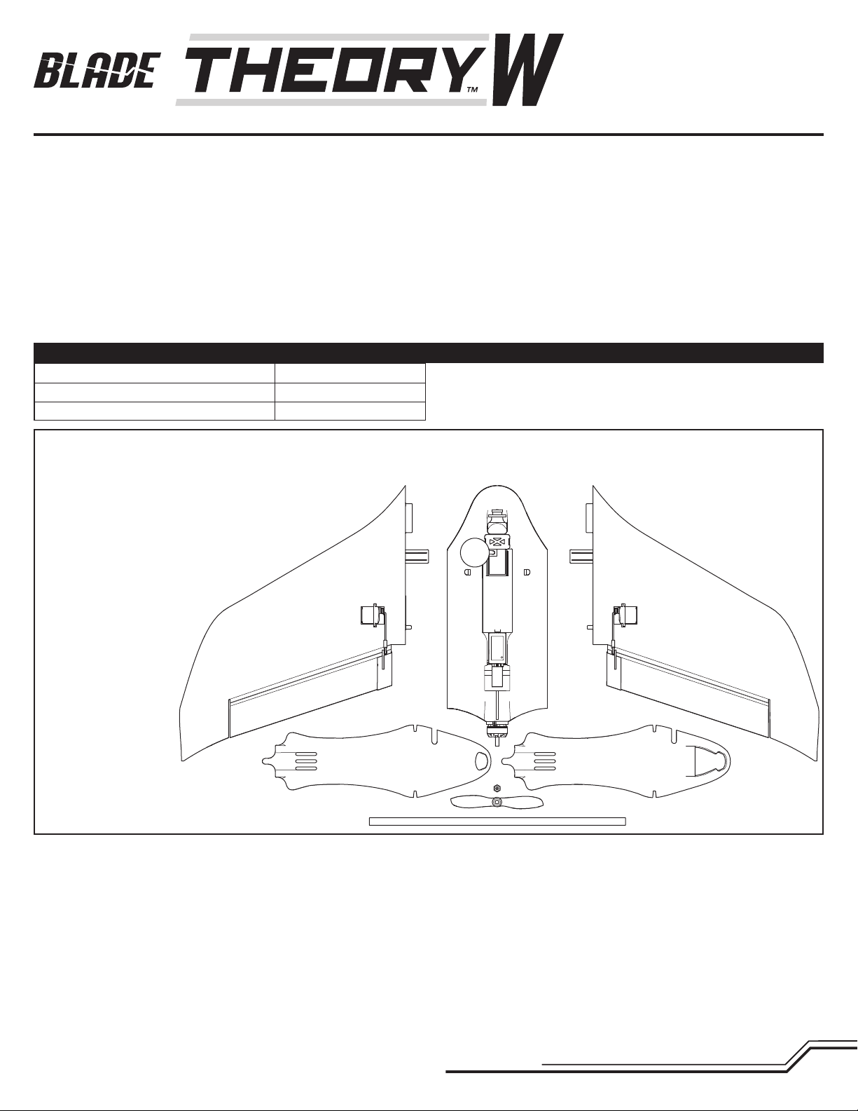
Specifi cations
Wingspan
Length
Flying Weight
Box Contents:
• Theory™ Type W FPV Wing • Decals (located under the foam packing)
Needed to Complete (FPV Equipped):
• Battery (4S, 1300mAh or 3S, 1300mAh LiPo)
• LiPo compatible charger
• DSM2
®
/DSMX® compatible, full range transmitter
• 5.8GHz FPV headset or ground station
Needed to Complete (FPV Ready):
• FPV Camera (SPMVC650)
• Video Transmitter
• Video Antenna (SPMVX5802)
• Battery (4S, 1300mAh or 3S,
1300mAh LiPo)
• LiPo compatible charger
• DSM2
• 5.8GHz FPV headset or
®
/DSMX® compatible,
full range transmitter
ground station
30 in (762mm)
14.2 in (360mm)
16.9 oz (480 g)
Using the Video Transmitter ...................................................................................9
Focusing the FPV Camera ...................................................................................10
Installing an Optional HD Video Camera...............................................................10
Removing the Motor ...........................................................................................10
AS3X Troubleshooting Guide ...............................................................................11
Troubleshooting Guide ........................................................................................11
Parts Explosion ...................................................................................................12
Replacement Parts ..............................................................................................12
Optional Parts .....................................................................................................12
Limited Warranty ................................................................................................13
Warranty and Service Contact Information ..........................................................13
FCC Information .................................................................................................. 14
IC Information .....................................................................................................14
Focus Pattern......................................................................................................15
To receive product updates, special offers and more, register your product at www.bladehelis.com.
3
EN
First Flight Preparation
• Remove and inspect contents
• Begin charging the fl ight battery
• Assemble the aircraft
• Program your computer transmitter
• Install the fl ight battery in the aircraft (once it has been fully charged)
• Bind your transmitter
• Familiarize yourself with the controls
• Find a suitable area for fl ying
Flying Checklist
❏ Always turn the transmitter on fi rst
❏ Plug the fl ight battery into the lead from the ESC
❏ Allow the ESC to initialize and arm properly
❏ Fly the model
❏ Land the model
❏ Unplug the fl ight battery from the ESC
❏ Always turn the transmitter off last
FPV Ready Version Assembly
If you purchased the FPV ready version of the Theory Type W fl ying wing, use the following instructions to install your FPV components to the airframe.
NOTICE: When using cyanoacrylate (CA) adhesive to join or repair the airframe, DO NOT allow the adhesive to contact or get close to the fpv camera lens. The vapors
from the adhesive will permanently fog the camera lens.
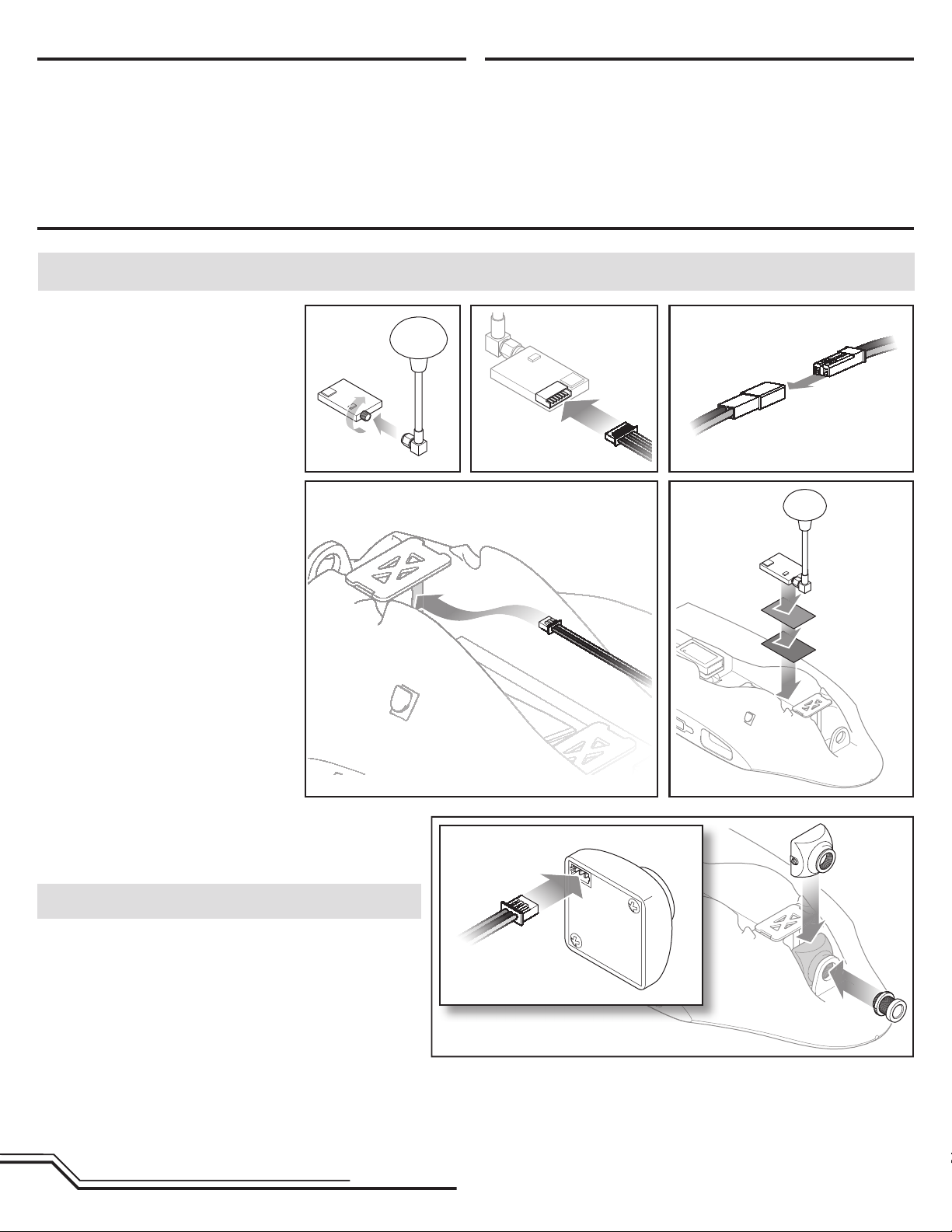
Install the Video Transmitter
1. Attach the video transmitter antenna to the
transmitter.
2. Connect the 6-port jst plug to the transmitter.
3. Connect the power lead to the battery lead
from the ESC.
4. Route the camera lead into the fpv camera
compartment.
5. Use hook and loop material to secure the
video transmitter in the bottom of the battery
compartment, routing the antenna to fi t out
of the top of the canopy. Ensure the digital
display and channel select button on the video
transmitter are facing up.
12 3
45
Install the FPV Camera
1. Loosen the lens locking ring.
2. Carefully unscrew the lens from the camera body. Leave the locking
ring on the lens barrel.
NOTICE: Do not allow dust or debris into the camera body when the
lens is removed.
3. Connect the camera lead from the video transmitter to the camera.
4. Slide the camera body behind the ring mount.
5. Screw the lens barrel through the ring mount into the camera body. Do
not completely tighten the barrel into the camera body.
6. Tighten the locking ring against the ring mount to secure the camera.
7. Proceed to the Focusing the FPV Camera section to correctly focus the
camera lens.
EN
4
Airframe Assembly
Prior to beginning assembly, inspect all of the foam parts. Using a hobby knife or sandpaper, remove any excess fl ash or rough edges.
NOTICE: When using cyanoacrylate (CA) adhesive to join or repair the airframe, DO NOT allow the adhesive to contact or get close to the fpv camera lens. The vapors
from the adhesive will permanently fog the camera lens.
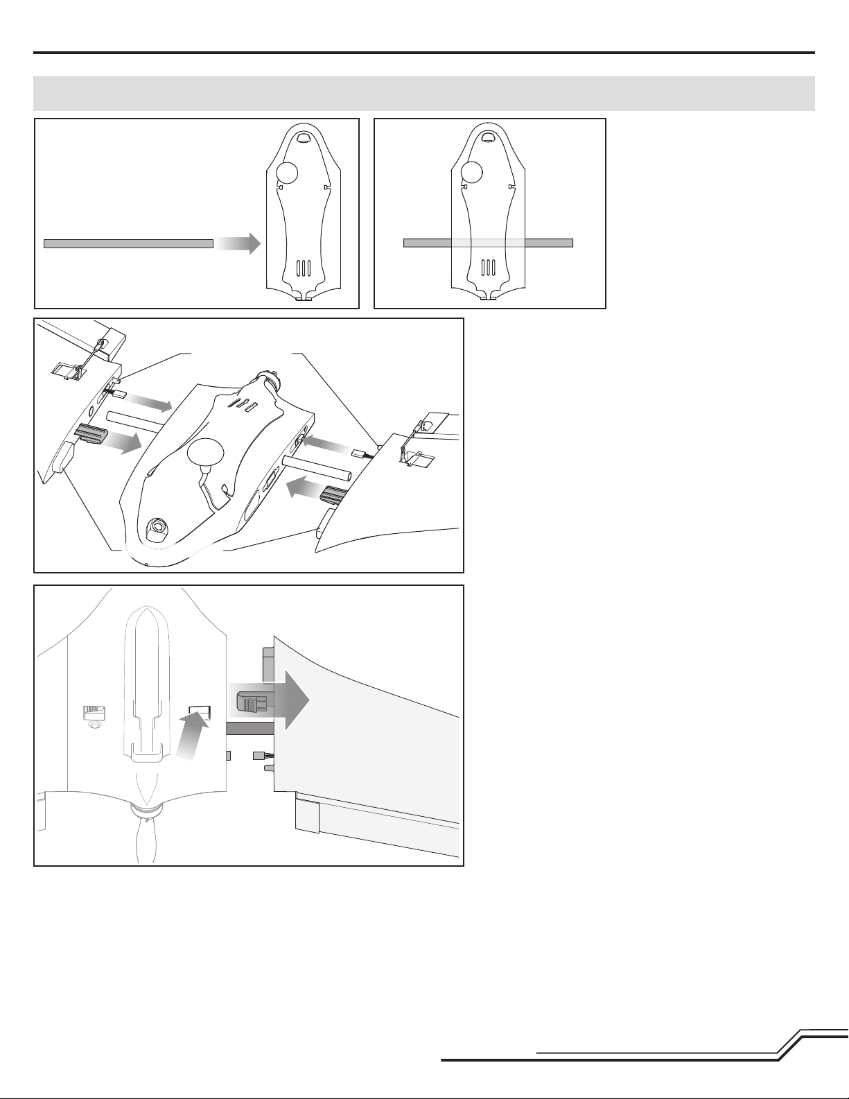
Install the Spar
1. Slide the wing spar through the center
section until it is centered.
Inspect the Wings
Prior to installing the wings every time, particularly after a crash or hard
Wing Alignment Pins
landing, inspect the wing alignment pins and pockets for any damage. If
the pins or pockets are damaged, repair or replace the wing panels prior
to attempting to fl y.
Install the Wings
1. Slide the wing panel partially onto the wing spar.
2. Connect the elevon servo connector to the port in the center section.
3. Slide the wing fully onto the wing spar, lining up the wing alignment
pins with the holes in the center section. Be careful to not trap the
servo wire in the wing joint. The patent pending wing lock mechanism
will click when the wing is fully seated.
4. Repeat for the opposite wing.
Wing Alignment Pins
To Remove the Wings
1. Press the wing lock mechanism while carefully pulling the wing away
from the center section.
2. Disconnect the elevon servo connector from the center section.
3. Pull the wing section off of the wing spar.
4. Remove the opposite wing in the same manner.
5. Remove the wing spar if desired.
5
EN
 Loading...