

Blade Night 230 S, BLH4480 Instruction Manual

Instruction Manual
Bedienungsanleitung
Manuel d’utilisation
Manuale di Istruzioni
2
EN
WARNING: Read the ENTIRE instruction manual to become familiar with the features of the product before
operating. Failure to operate the product correctly can result in damage to the product, personal property and
cause serious injury.
This is a sophisticated hobby product. It must be operated with caution and common sense and requires some basic
mechanical ability. Failure to operate this Product in a safe and responsible manner could result in injury or damage
to the product or other property. This product is not intended for use by children without direct adult supervision. Do
not use with incompatible components or alter this product in any way outside of the instructions provided by Horizon
Hobby, LLC. This manual contains instructions for safety, operation and maintenance. It is essential to read and follow
all the instructions and warnings in the manual, prior to assembly, setup or use, in order to operate correctly and avoid
damage or serious injury.
The following terms are used throughout the product literature to indicate various levels of potential harm when
operating this product:
NOTICE: Procedures, which if not properly followed, create a possibility of physical property damage AND a little or no
possibility of injury.
CAUTION: Procedures, which if not properly followed, create the probability of physical property damage AND a
possibility of serious injury.
WARNING: Procedures, which if not properly followed, create the probability of property damage, collateral damage,
and serious injury OR create a high probability of superfi cial injury.
• Always keep a safe distance in all directions around
your model to avoid collisions or injury. This model is
controlled by a radio signal subject to interference from
many sources outside your control. Interference can
cause momentary loss of control.
• Always operate your model in open spaces away from
full-size vehicles, traffi c and people.
• Always carefully follow the directions and warnings for
this and any optional support equipment
(chargers, rechargeable battery packs, etc.).
• Always keep all chemicals, small parts and anything
electrical out of the reach of children.
• Always avoid water exposure to all equipment not
specifi cally designed and protected for this purpose.
Moisture causes damage to electronics.
• Never place any portion of the model in your mouth as it
could cause serious injury or even death.
• Never operate your model with low transmitter
batteries.
• Always keep aircraft in sight and under control.
• Always move the throttle fully down at rotor strike.
• Always use fully charged batteries.
• Always keep transmitter powered on while aircraft is
powered.
• Always remove batteries before disassembly.
• Always keep moving parts clean.
• Always keep parts dry.
• Always let parts cool after use before touching.
• Always remove batteries after use.
• Never operate aircraft with damaged wiring.
• Never touch moving parts.
NOTICE
All instructions, warranties and other collateral documents are subject to change at the sole discretion of Horizon
Hobby, LLC. For up-to-date product literature, visit horizonhobby.com and click on the support tab for this product.
Meaning of Special Language
Safety Precautions and Warnings
Age Recommendation: Not for children under 14 years. This is not a toy.
WARNING AGAINST COUNTERFEIT PRODUCTS: If you ever need to replace your Spektrum receiver found in
a Horizon Hobby product, always purchase from Horizon Hobby, LLC or a Horizon Hobby authorized dealer to
ensure authentic high-quality Spektrum product. Horizon Hobby, LLC disclaims all support and warranty with regards,
but not limited to, compatibility and performance of counterfeit products or products claiming compatibility with
DSM or Spektrum.
3
EN
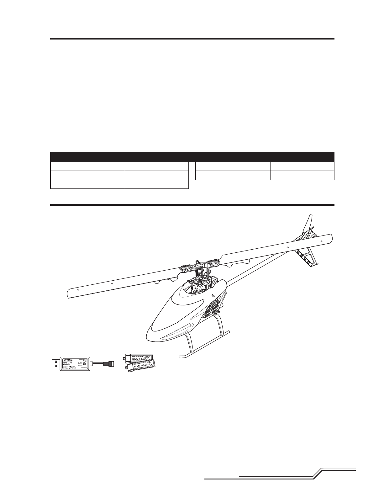
Box Contents
• Blade® Night 230 S
• 2, 150mAh 1S 3.7V 25C LiPo Batteries
• 1S 300 mA USB LiPo Charger
Table of Contents
Length
18.66 in (474mm)
Height
6.46 in (164 mm)
Main Rotor Diameter
21.10in (536mm)
Tail Rotor Diameter
3.25 in (82.5mm)
Flying Weight
11.95oz (339 g)
Specifications
Box Contents .................................................................... 3
First Flight Preparation ...................................................... 4
Flying Checklist ................................................................4
Charging Warnings............................................................4
LED Battery Charging ........................................................ 4
Transmitter Setup Table ....................................................5
Installing the Flight Battery (not included).......................... 7
Installing the LED Batteries ...............................................7
Transmitter and Receiver Binding ...................................... 7
SAFE
®
Technology ............................................................ 8
Flight Mode and Rate Selection ......................................... 8
Panic Recovery .................................................................8
Throttle Hold ..................................................................... 9
Control Tests ..................................................................... 9
Understanding the Primary Flight Controls ......................10
Flying the 230 S.............................................................. 11
Advanced Settings ..........................................................11
Servo Adjustment ........................................................... 13
Trim Flight ......................................................................14
Calibration Procedure .....................................................15
Post-Flight Inspection and Maintenance Checklist ........... 16
Troubleshooting Guide ....................................................16
Exploded View ................................................................ 18
Parts Listings .................................................................. 18
Optional Parts .................................................................19
Limited Warranty ............................................................ 19
Warranty and Service Contact Information ......................20
FCC Information .............................................................. 21
IC Information .................................................................21
Compliance Information for the European Union .............. 21
To receive product updates, special offers and more, register your product at www.bladehelis.com
Needed to Complete
• Minimum 800mAh 3S 11.1V LiPo
• 3S LiPo Charger
• DSM2®/DSMX® Compatible Transmitter

4
EN
NOTICE: Charge only batteries that are cool to the touch
and are not damaged. Look at the battery to make
sure it is not damaged e.g., swollen, bent, broken or
punctured.
1. Insert the charger into a USB port.
2. Connect the battery to the charger lead, noting the
correct polarity.
3. Always disconnect the fl ight battery from the charger
immediately upon completion of charging.
CAUTION: Only use chargers specifi cally designed
to charge the included Li-Po battery. Failure to do so
could result in fi re, causing injury or property damage.
CAUTION: Never exceed the recommended
charge rate.
LED Indications
When you make the connection successfully, the LED on
the charger turns solid red, indicating charging has begun.
Charging a fully discharged (not over-discharged) 750mAh
battery takes approximately 60 minutes. The light goes off
when the charge is complete.
CHARGING (Solid Red)
MAX CHARGE (OFF)
CAUTION: Once charging is complete, immediately
remove the battery. Never leave a battery connected
to the charger.
CAUTION: All instructions and warnings
must be followed exactly. Mishandling of Li-Po
batteries can result in a fi re, personal injury and/or
property damage.
• NEVER LEAVE CHARGING BATTERIES UNATTENDED.
• NEVER CHARGE BATTERIES OVERNIGHT.
• By handling, charging or using the included Li-Po
battery, you assume all risks associated with lithium
batteries.
• If at any time the battery begins to balloon or swell,
discontinue use immediately. If charging or discharging,
discontinue and disconnect. Continuing to use, charge
or discharge a battery that is ballooning or swelling can
result in fi re.
• Always store the battery at room temperature in a dry
area for best results.
• Always transport or temporarily store the battery in a
temperature range of 40–120º F (5–49° C).
• Do not store battery or model in a car or direct sunlight.
If stored in a hot car, the battery can be damaged or
even catch fi re.
• Always charge batteries away from fl ammable
materials.
• Always inspect the battery before charging
• Always disconnect the battery after charging, and
let the charger cool between charges.
• Always constantly monitor the temperature of the
battery pack while charging.
• ONLY USE A CHARGER SPECIFICALLY DESIGNED TO
CHARGE LI-PO BATTERIES. Failure to charge the battery
with a compatible charger may cause a fi re resulting in
personal injury and/or property damage.
• Never discharge Li-Po cells to below 3V under load.
• Never cover warning labels with hook and loop strips.
• Never charge batteries outside recommended levels.
• Never charge damaged batteries.
• Never attempt to dismantle or alter the charger.
• Never allow minors to charge battery packs.
• Never charge batteries in extremely hot or cold places
(recommended between 40–120° F or
(5–49° C) or place in direct sunlight.
Charging Warnings
LED Battery Charging
First Flight Preparation
• Remove and inspect contents
• Begin charging the fl ight and LED batteries
• Program your computer transmitter
• Install the fl ight and LED batteries in the helicopter
(once they have been fully charged)
• Bind your transmitter
• Familiarize yourself with the controls
• Find a suitable area for fl ying
Flying Checklist
❏ Always turn the transmitter on fi rst
❏ Install the LED batteries
❏ Plug the fl ight battery into the lead from the ESC
❏ Allow the receiver and ESC to initialize and arm properly
❏ Fly the model
❏ Land the model
❏ Unplug the fl ight battery from the ESC
❏ Always turn the transmitter off last
USB Li-Po
Charger
EFLC1015
SOLID RED LED
–Charging
DC Input:5.0V 350mA
DC Output:4.2V 300mA
LED OFF
–Charge
Complete
5
EN
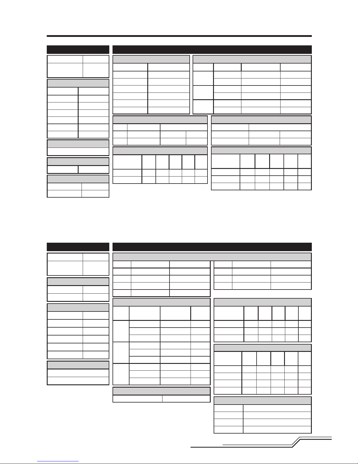
Transmitter Setup Table
D/R & Expo
Chan
Switch Pos
(Ail D/R) D/R Expo
AILE
0 100/100 +25
1 100/100 +25
2 75/75 +25
ELEV
0 100/100 +25
1 100/100 +25
2 75/75 +25
RUDD
0 100/100 +25
1 100/100 +25
2 75/75 +25
Throttle Hold
Throttle 0%
D/R & Expo
Chan Sw Pos D/R Expo
AILE
0 100 +25
1 75 +25
ELEV
0 100 +25
1 75 +25
RUDD
0 100 +25
1 75 +25
Mix 1
GYRO->GYRO ACT
Rate D+125% U+125%
SW ELE D/R TRIM – INH
Timer
Mode Count Down
Time 5:00 Tone
Start Throttle Out
Over 25%
Timer
Down Timer 5:00
Switch THR CUT
SYSTEM SETUP
Model Type HELI
Swash Type 1 servo
Normal
F-Mode Setup
Flight Mode F Mode
Hold Hold
SW Select
Trainer Aux 2
F Mode Gear
Gyro INH
Mix INH
Hold INH
Knob INH
Frame Rate
11ms
DSMX
Chan Travel Reverse
THR 100/100 Normal
AIL 100/100 Normal
ELE 100/100 Normal
RUD 100/100 Normal
Chan Travel Reverse
GER 100/100 Normal
PIT 100/100 Normal
AX2 100/100 Normal
Servo Setup
FUNCTION LIST
ADJUST LISTSETUP LIST
DX6i
DX7s, DX8
Throttle Curve
Switch Pos
(F Mode)
Pos 1Pos 2Pos 3Pos 4Pos
5
NORM 0 25 50 75 100
STUNT 100 90 85 90 100
Throttle Curve
Switch Pos
(F Mode) Pt 1 Pt 2 Pt 3 Pt 4 Pt 5
N 0 25 50 75 100
1 100 80 75 80 100
2 100 90 85 90 100
TRAVEL ADJ
Channel Travel
THRO 100/100
AILE 100/100
ELEV 100/100
RUDD 100/100
GYRO 100/100
PITC 100/100
REVERSE
Channel Direction
THRO N
AILE N
ELEV N
RUDD N
GYRO N
PITC R
GYRO
RATE SW-F.MODE
0 88% NORM 0
1 12% STUNT 1
Modulation Type
AUTO DSMX-ENABLE
D/R COMBI
D/R SW AILE
Model Type HELI
Swash Type
1 servo
Normal
Pitch Curve
Switch Pos
(F Mode)
Pos 1Pos 2Pos 3Pos 4Pos
5
NORM 30 40 50 75 100
STUNT 0 25 50 75 100
HOLD 25 37 50 75 100
Pitch Curve
Switch Pos
(F Mode) Pt 1 Pt 2 Pt 3 Pt 4 Pt 5
N 30 40 50 75 100
1 0 25 50 75 100
2 0 25 50 75 100
HOLD 25 37 50 75 100
Panic Mode Operation
ELEV D/R Switch
Sw Pos 0 = Panic Mode Off
Sw Pos 1 = Panic Mode On
Once the model has returned to level you must manually return the Panic Mode
Switch to the off position otherwise the cyclic and tail rotor controls will be reduced.
Panic Mode Operation
Trainer/Bind Button
Pressed = Panic Mode On
Released = Panic Mode Off
6
EN
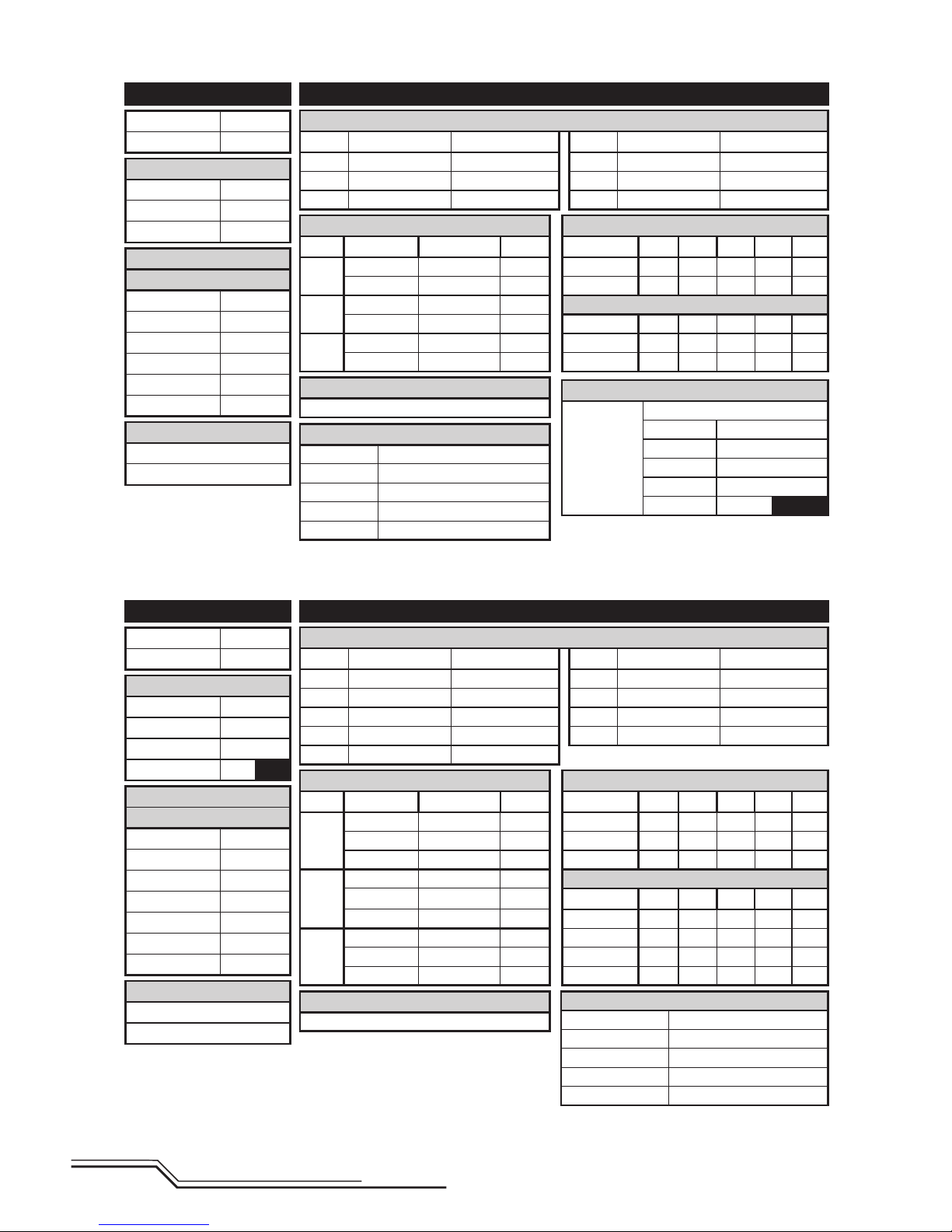
D/R & Expo Throttle Curve
Chan Sw (F) Pos D/R Expo Sw (B) Pos Pt 1 Pt 2 Pt 3 Pt 4 Pt 5
AILE
0 100/100 +25 N 0 25 50 75 100
1 75/75 +25 2 100 90 85 90 100
ELEV
0 100/100 +25 Pitch Curve
1 75/75 +25 N 30 40 50 75 100
RUDD
0 100/100 +25 1 0 25 50 75 100
1 75/75 +25 HOLD 25 37 50 75 100
Gyro
Inhibit
D/R & Expo Throttle Curve
Chan Sw (F) Pos D/R Expo Sw (B) Pos Pt 1 Pt 2 Pt 3 Pt 4 Pt 5
AILE
0 100/100 +25 N 0 25 50 75 100
1 100/100 +25 1 100 80 75 80 100
2 75/75 +25 2 100 90 85 90 100
ELEV
0 100/100 +25 Pitch Curve
1 100/100 +25
Sw (B) Pos Pt 1 Pt 2 Pt 3 Pt 4 Pt 5
2 75/75 +25 N 30 40 50 75 100
RUDD
0 100/100 +25 1 0 25 50 75 100
1 100/100 +25 2 0 25 50 75 100
2 75/75 +25 HOLD 25 37 50 75 100
Gyro
Inhibit
Mixing
P-Mix 1
Normal
Channels -I- > Ger
Rate 0/–125
Offset 100
Switch Switch I
Position 0
1
Timer
Mode Count Down
Time 5:00
Start Throttle Out
Over 25%
One Time Inhibit
SYSTEM SETUP
Model Type HELI
Swash Type Normal
F-Mode Setup
Switch 1 Switch B
Switch 2 Inhibit
Hold Switch Switch H
Channel Assign
Channel Input Confi g
1 Throttle
2 Aileron
3 Elevator
4 Rudder
5 Flight Mode Switch B
6 Collective
Frame Rate
11ms
DSMX
Chan Travel Reverse
THR 100/100 Normal
AIL 100/100 Normal
ELE 100/100 Normal
Chan Travel Reverse
RUD 100/100 Normal
GER 100/100 Normal
PIT 100/100 Normal
Chan Travel Reverse
THR 100/100 Normal
AIL 100/100 Normal
ELE 100/100 Normal
RUD 100/100 Normal
GER 100/100 Normal
Chan Travel Reverse
PIT 100/100 Normal
AX2 100/100 Normal
AX3 100/100 Normal
AX4 100/100 Normal
Servo Setup
Servo Setup
FUNCTION LIST
FUNCTION LIST
DX6
DX7 (new), DX8G2, DX9, DX18
Panic Mode Operation
Bind / I Button
Pressed = Panic Mode On
Released = Panic Mode Off
Panic Mode Operation
Bind / I Button
Pressed = Panic Mode On
Released = Panic Mode Off
Timer
Mode Count Down
Time 5:00
Start Throttle Out
Over 25%
One Time Inhibit
SYSTEM SETUP
Model Type HELI
Swash Type Normal
F-Mode Setup
Switch 1 Switch B
Switch 2 Inhibit
Hold Switch Switch H
0
1
Channel Assign
Channel Input Confi g
1 Throttle
2 Aileron
3 Elevator
4 Rudder
5 Gear Switch B
6 Collective
7 AUX 2 Switch I
Frame Rate
11ms
DSMX
7
EN
This product requires an approved Spektrum DSM2®/DSMX® compatible transmitter.
Visit www.bindnfl y.com for a complete list of approved transmitters.
General Binding Procedure
1. Disconnect the fl ight battery from the helicopter.
2. Refer the Transmitter Setup Table to correctly setup your transmitter.
3. Lower the throttle stick to the lowest position. Set all trims to the center position.
4. Power off the transmitter and move all switches to the 0 position. Move the throttle to the low/off position.
5. Install the bind plug in the receiver BIND/PROG port (far left side of the receiver).
6. Connect the fl ight battery to the ESC. The receiver LED fl ashes, indicating it is in bind mode.
7. Put the transmitter into bind mode while powering on the transmitter.
8. Release the bind button/switch after 2–3 seconds. The helicopter is bound when the LED on the receiver turns solid.
9. Disconnect the fl ight battery and power the transmitter off.
CAUTION: When using a Futaba
®
transmitter with a Spektrum™ DSM2® module, you must reverse the
throttle channel and re-bind. Refer to your Spektrum module manual for binding and failsafe instructions.
Refer to your Futaba transmitter manual for instructions on reversing the throttle channel.
Transmitter and Receiver Binding
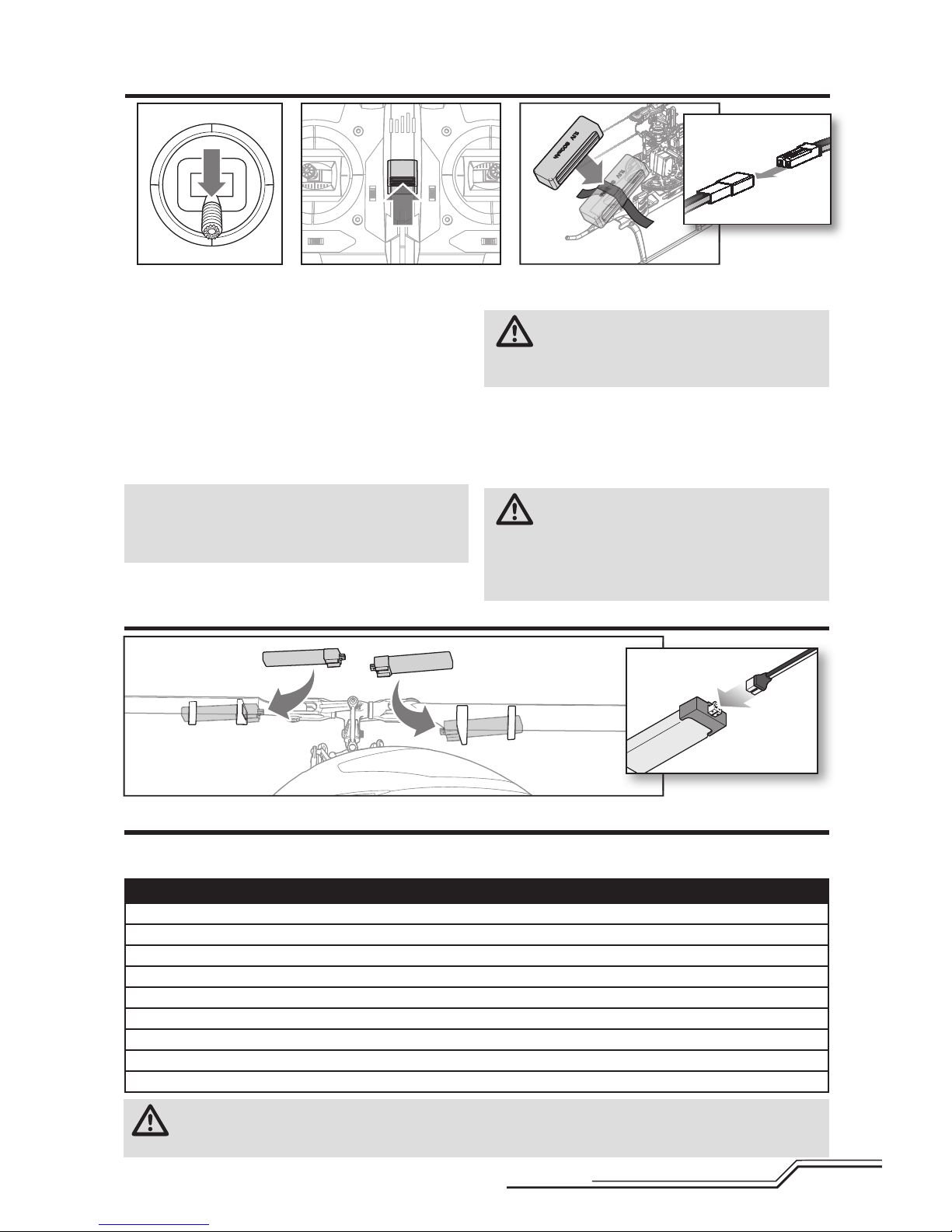
1. Lower the throttle stick to the lowest position.
2. Power ON the transmitter.
3. Center all trims. For the included Spektrum DXe
transmitter (RTF only), the trims are centered when
you hear a higher pitched beep while pressing the trim
button. Move the trim in both directions until you hear
the high-pitched beep.
4. Attach the hook material to the helicopter frame and
the loop material to the fl ight battery.
5. Install the fl ight battery on the helicopter frame.
Secure the fl ight battery with a hook and loop strap.
NOTICE: If the fl ight battery hook and loop strap is pulled
too tight, it may result in a vibration or the tail rotor may
drift to the right during fl ight. If you experience either of
these issues, loosen the strap slightly and fl y again.
6. Connect the battery connector to the ESC, noting
correct polarity.
CAUTION: Connecting the battery to the ESC
with reversed polarity will cause damage to the
ESC, the battery or both. Damage caused by incorrectly
connecting the battery is not covered under warranty.
7. Place the helicopter on a fl at surface and leave it still
until the ESC beeps twice and the blue LED glows
solid, indicating initialization is complete.
If you experience issues during initialization, refer to the
Troubleshooting Guide at the back of the manual.
CAUTION: Always disconnect the Li-Po
battery from the aircraft when not fl ying to
avoid over-discharging the battery. Batteries discharged
to a voltage lower than the lowest approved voltage may
become damaged, resulting in loss of performance and
potential fi re when batteries are charged.
Installing the Flight Battery (not included)
Installing the LED Batteries
2X
 Loading...