

Page 1

Instruction Manual
Bedienungsanleitung
Manuel d’utilisation
Manuale di istruzioni
RTF
Page 2

2
EN
• Always keep a safe distance in all
directions around your model to avoid
collisions or injury. This model is controlled
by a radio signal subject to interference
from many sources outside your control.
Interference can cause momentary loss
of control.
• Always operate your model in open spaces
away from full-size vehicles, traffi c and
people.
• Always carefully follow the directions and
warnings for this and any optional support
equipment (chargers, rechargeable battery
packs, etc.).
• Always keep all chemicals, small parts
and anything electrical out of the reach of
children.
• Always avoid water exposure to all
equipment not specifi cally designed
and protected for this purpose. Moisture
causes damage to electronics.
• Never place any portion of the model in
your mouth as it could cause serious injury
or even death.
• Never operate your model with low
transmitter batteries.
• Always keep aircraft in sight and under
control.
• Always move the throttle fully down at
rotor strike.
• Always use fully charged batteries.
• Always keep transmitter powered on while
aircraft is powered.
• Always remove batteries before
disassembly.
• Always keep moving parts clean.
• Always keep parts dry.
• Always let parts cool after use before
touching.
• Always remove batteries after use.
• Never operate aircraft with damaged
wiring.
• Never touch moving parts.
Age Recommendation: Not for children under 14 years. This is not a toy.
WARNING: Read the ENTIRE instruction manual to become familiar with the
features of the product before operating. Failure to operate the product correctly
can result in damage to the product, personal property and cause serious injury.
This is a sophisticated hobby product. It must be operated with caution and common
sense and requires some basic mechanical ability. Failure to operate this Product in a
safe and responsible manner could result in injury or damage to the product or other
property. This product is not intended for use by children without direct adult supervision.
Do not use with incompatible components or alter this product in any way outside of the
instructions provided by Horizon Hobby, LLC. This manual contains instructions for safety,
operation and maintenance. It is essential to read and follow all the instructions and warnings in the manual, prior to assembly, setup or use, in order to operate correctly and avoid
damage or serious injury.
The following terms are used throughout the product literature to indicate various levels of
potential harm when operating this product:
NOTICE: Procedures, which if not properly followed, create a possibility of physical property
damage AND a little or no possibility of injury.
CAUTION: Procedures, which if not properly followed, create the probability of physical
property damage AND a possibility of serious injury.
WARNING: Procedures, which if not properly followed, create the probability of property damage, collateral damage, and serious injury OR create a high probability of superfi cial injury.
NOTICE
All instructions, warranties and other collateral documents are subject to change at the
sole discretion of Horizon Hobby, LLC. For up-to-date product literature, visit horizonhobby.
com and click on the support tab for this product.
Meaning of Special Language
Safety Precautions and Warnings
Page 3
3
EN
Length
200mm
Height
79mm
Flying Weight
32g
Main Rotor Diameter
205mm
Tail Rotor Diameter
40mm
Specifi cations
Components RTF BNF
Airframe
Blade Nano CPS
Included Included
Motors
Brushed
Installed Installed
Flybarless Unit
3-in-1 Control Unit with SAFE®
technology
Installed Installed
Battery
150mAh 1S 3.7V 45C Li-Po
Battery
Included Included
Charger
1S USB Li-Po Charger, 300mA
Included Included
Transmitter
DSM2®/DSMX® Compatible
Transmitter
MLP6DSM
Included
Required
Transmitter Batteries
4 AA
Included Required
Visit www.bladehelis.com
to register your helicopter
Table of Contents
Box Contents .............................................. 3
Charging Warnings...................................... 4
Battery Charging .........................................4
Transmitter Setup Table (BNF) ..................... 5
Transmitter Control (RTF) ............................ 7
Installing the Flight Battery ......................... 7
Transmitter and Receiver Binding ................ 8
Control Tests ............................................... 8
Understanding the
Primary Flight Controls ...............................9
SAFE Technology ...................................... 10
Flight Modes ............................................. 10
Panic Recovery ......................................... 11
First Flight Preparation .............................. 11
Flying Checklist ........................................ 11
Flying the Nano CPS ................................. 11
Exploded View and Parts Listings .............. 12
Optional Parts ........................................... 13
Troubleshooting Guide ..............................14
Limited Warranty ...................................... 15
Warranty and Service
Contact Information ..................................16
FCC Information ........................................ 16
IC Information ........................................... 16
Compliance Information
for the European Union .............................16
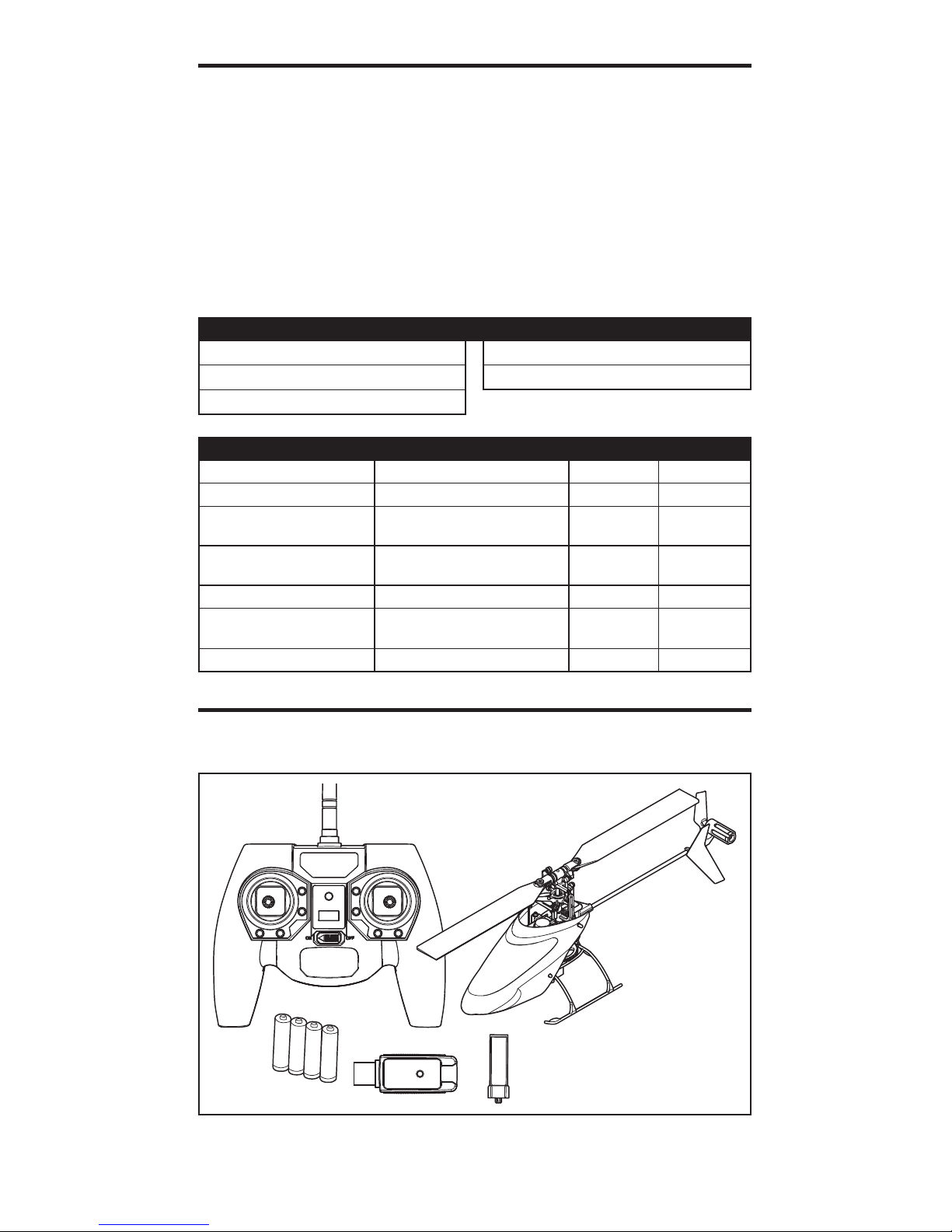
Box Contents
• Blade Nano CPS
• 150mAh 1S 3.7V 45C Li-Po Battery
• 1S USB Li-Po Charger, 300mA
• DXe Transmitter (RTF Only)
• 4 AA Batteries (RTF Only)
Page 4
4
EN
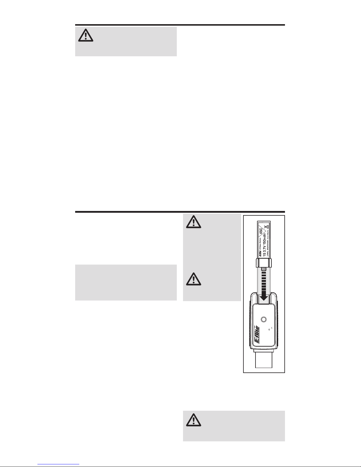
Your aircraft comes with a 1S 3.7V DC Li-Po
battery charger and 1S 3.7V 150mAh 45C LiPo battery. Refer to the charging warnings.
It is recommended to charge the battery
pack while you are inspecting the aircraft.
The fl ight battery will be required to confi rm
proper aircraft operation in future steps.
NOTICE: Charge only batteries that are
cool to the touch and are not damaged.
Look at the battery to make sure it is not
damaged e.g., swollen, bent, broken or
punctured.
1. Insert the charger into a USB port. The
charger only uses power from the USB
port, it will not connect to your computer.
USB power supplies, such as those used
to charge cellular phones, can also be
used.
2. Slide the battery into the slot on the
charger and press it into the charge
jack/connector located at the bottom of
the slot. The end cap of the battery is
specifi cally designed to allow the battery
to fi t into the slot one way (usually with
the label on the battery facing outward)
to prevent reverse polarity connection,
however, check for proper alignment and
polarity.
3. Always disconnect the fl ight battery from
the charger immediately upon completion of charging.
CAUTION: Only
use chargers
specifi cally designed
to charge the included
Li-Po battery. Failure
to do so could result in
fi re, causing injury or
property damage.
CAUTION:
Never exceed
the recommended
charge rate.
LED Indications
When you make the
connection successfully, the LED on the
charger turns solid red,
indicating charging
has begun. Charging a fully discharged
(not over-discharged)
150mAh battery takes
approximately 30–40
minutes. The light goes out when the charge
is complete.
Solid Red: Charging
OFF: Max Charge
CAUTION: Once charging is
complete, immediately remove the
battery. Never leave a battery connected to
the charger.
Battery Charging
USB Li-Po
Charger
EFLC1008
SOLID RED LED
–Charging
DC Input:5.0V 350mA
DC Output:4.2V 300mA
LED OFF
–Charge
Complete
CAUTION: All instructions and
warnings must be followed exactly.
Mishandling of Li-Po batteries can result in a
fi re, personal injury and/or property damage.
• NEVER LEAVE CHARGING BATTERIES
UNATTENDED.
• NEVER CHARGE BATTERIES OVERNIGHT.
• By handling, charging or using the included
Li-Po battery, you assume all risks associated
with lithium batteries.
• If at any time the battery begins to balloon or
swell, discontinue use immediately. If charging
or discharging, discontinue and disconnect.
Continuing to use, charge or discharge a
battery that is ballooning or swelling can result
in fi re.
• Always store the battery at room temperature
in a dry area for best results.
• Always transport or temporarily store the
battery in a temperature range of 40–120º F
(5–49° C).
• Do not store battery or model in a car or direct
sunlight. If stored in a hot car, the battery can
be damaged or even catch fi re.
• Always charge batteries away from fl ammable
materials.
• Always inspect the battery before charging
• Always disconnect the battery after charging,
and let the charger cool between charges
• Always constantly monitor the temperature of
the battery pack while charging.
• ONLY USE A CHARGER SPECIFICALLY
DESIGNED TO CHARGE LI-PO BATTERIES.
Failure to charge the battery with a compatible
charger may cause a fi re resulting in personal
injury and/or property damage.
• Never discharge Li-Po cells to below 3V under
load.
• Never cover warning labels with hook and
loop strips.
• Never charge batteries outside recommended
levels.
• Never charge damaged batteries.
• Never attempt to dismantle or alter the
charger.
• Never allow minors to charge battery packs.
• Never charge batteries in extremely hot or cold
places (recommended between 40–120° F or
(5–49° C) or place in direct sunlight.
Charging Warnings
Page 5
5
EN
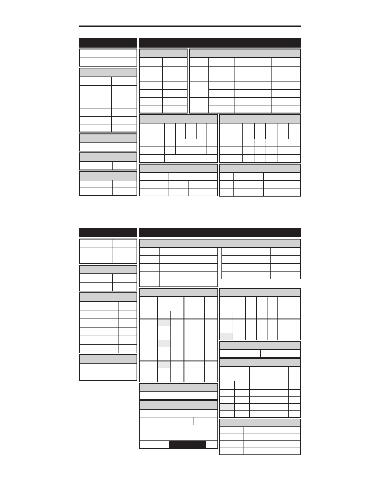
Transmitter Setup Table (BNF)
D/R & Expo
Chan
Switch Pos
(Ail D/R)
D/R
ExpoDX7s
DX8
AILE
0 100/100 +25
0 1 100/100 +25
1 2 75/75 +25
ELEV
0 100/100 +25
0 1 100/100 +25
1 2 75/75 +25
RUDD
0 100/100 +25
0 1 100/100 +25
1 2 75/75 +25
Timer
Mode Count Down
Time 4:00 Tone
Start Throttle Out
Over 25%
Chan Travel Reverse
THR 100/100 Normal
AIL 100/100 Normal
ELE 100/100 Normal
RUD 100/100 Normal
Chan Travel Reverse
GER 100/100 Normal
PIT 100/100 Normal
AX2 100/100 Normal
Servo Setup
FUNCTION LISTSYSTEM SETUP
DX7s, DX8
Throttle Curve
Switch Pos
(F Mode)
Pt 1 Pt 2 Pt 3 Pt 4 Pt 5DX7s DX8
N N 0 25 50 75 100
1 1 100 80 75 80 100
2 100 100 100 100 100
Pitch Curve
Switch Pos
(F Mode)
Pt 1 Pt 2 Pt 3 Pt 4 Pt 5DX7s DX8
N N 30 40 50 75 100
1 1 0 25 50 75 100
2 0 25 50 75 100
HOLD HOLD 25 37 50 75 100
Panic Mode Operation
Trainer/Bind Button
Pressed = Panic Mode On
Released = Panic Mode Off
Panic Mode Operation
Gyro Switch: Pos 0 = Panic Mode Off
Pos 1 = Panic Mode On
Throttle Cut
Throttle 0%
Gyro
INH
D/R & Expo
Chan Sw Pos D/R Expo
AILE
0 100 +25
1 75 +25
ELEV
0 100 +25
1 75 +25
RUDD
0 100 +25
1 75 +25
Timer
Down Timer 4:00
Switch THR CUT
ADJUST LISTSETUP LIST
DX6i
Throttle Curve
Switch Pos
(F Mode)
Pos 1Pos 2Pos 3Pos 4Pos
5
NORM 0 25 50 75 100
STUNT 100 100 100 100 100
HOLD 0
TRAVEL ADJ
Channel Travel
THRO 100/100
AILE 100/100
ELEV 100/100
RUDD 100/100
GYRO 100/100
PITC 100/100
REVERSE
Channel Direction
THRO N
AILE N
ELEV N
RUDD N
GYRO N
PITC R
Modulation Type
AUTO DSMX-ENABLE
D/R COMBI
D/R SW AILE
Model Type HELI
Swash Type
1 servo 90
Pitch Curve
Switch Pos
(F Mode)
Pos 1Pos 2Pos 3Pos 4Pos
5
NORM 30 40 50 75 100
STUNT 0 25 50 75 100
HOLD 0 25 50 75 100
Mixing
GYRO->GYRO
ACT
Rate
D –80%
U +0%
SW GYRO TRIM – INH
GYRO
RATE SW-F.MODE
0 90% NORM 0
1 15% STUNT 1
Mixing
Channels AUX2 > GER
Rate 100% 20%
Offset 100%
Trim INH
Position NIHM
Model Type HELI
Swash Type
1 servo
Normal
F-Mode Setup
Flight Mode F Mode
Hold Hold
SW Select
Trainer Aux 2
F Mode Gear
Gyro INH
Mix INH
Hold INH
Knob INH
Frame Rate
11ms
DSMX
Page 6
6
EN
D/R & Expo
Chan Sw (F) Pos D/R Expo
AILE
0 100/100 +25
1 75/75 +25
ELEV
0 100/100 +25
1 75/75 +25
RUDD
0 100/100 +25
1 75/75 +25
D/R & Expo
Chan Sw (F) Pos D/R Expo
AILE
0 100/100 +25
1 100/100 +25
2 75/75 +25
ELEV
0 100/100 +25
1 100/100 +25
2 75/75 +25
RUDD
0 100/100 +25
1 100/100 +25
2 75/75 +25
Timer
Mode Count Down
Time 4:00
Start Throttle Out
Over 25%
One Time Inhibit
Chan Travel Reverse
THR 100/100 Normal
AIL 100/100 Normal
ELE 100/100 Normal
Chan Travel Reverse
RUD 100/100 Normal
GER 100/100 Normal
PIT 100/100 Normal
Chan Travel Reverse
THR 100/100 Normal
AIL 100/100 Normal
ELE 100/100 Normal
RUD 100/100 Normal
GER 100/100 Normal
Chan Travel Reverse
PIT 100/100 Normal
AX2 100/100 Normal
AX3 100/100 Normal
AX4 100/100 Normal
Servo Setup
Servo Setup
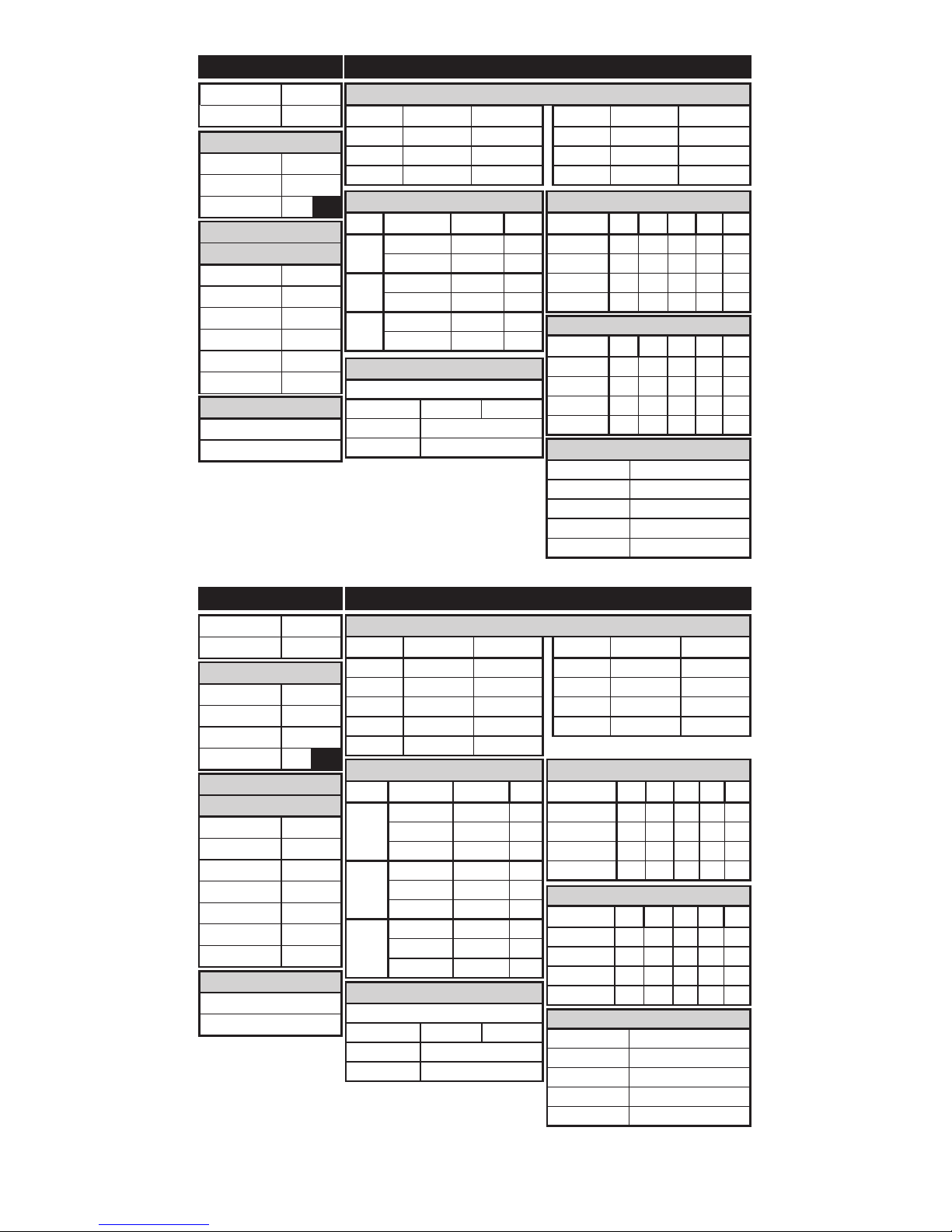
FUNCTION LISTSYSTEM SETUP
FUNCTION LISTSYSTEM SETUP
DX7 (new), DX9, DX18
Panic Mode Operation
Bind / I Button
Pressed = Panic Mode On
Released = Panic Mode Off
Panic Mode Operation
Bind / I Button
Pressed = Panic Mode On
Released = Panic Mode Off
Timer
Mode Count Down
Time 4:00
Start Throttle Out
Over 25%
One Time Inhibit
Throttle Curve
Sw (B) Pos Pt 1 Pt 2 Pt 3 Pt 4 Pt 5
N 0 25 50 75 100
1 100 80 75 80 100
2 100 100 100 100 100
HOLD 0 0 0 0 0
Throttle Curve
Sw (B) Pos Pt 1 Pt 2 Pt 3 Pt 4 Pt 5
N 0 25 50 75 100
1 100 80 75 80 100
2 100 100 100 100 100
HOLD 0 0 0 0 0
Pitch Curve
Sw (B) Pos Pt 1 Pt 2 Pt 3 Pt 4 Pt 5
N 30 40 50 75 100
1 0 25 50 75 100
2 0 25 50 75 100
HOLD 0 25 50 75 100
Pitch Curve
Sw (B) Pos Pt 1 Pt 2 Pt 3 Pt 4 Pt 5
N 30 40 50 75 100
1 0 25 50 75 100
2 0 25 50 75 100
HOLD 0 25 50 75 100
Mixing
GER -> GER
Rate 100% 100%
Offset 20%
Switch Switch I
Mixing
GER -> GER
Rate 100% 100%
Offset 20%
Switch Switch I
DX6
Model Type HELI
Swash Type Normal
F-Mode Setup
Switch 1 Switch B
Hold Switch Switch H
0
1
Channel Assign
Channel Input
1 Throttle Throttle
2 Aileron Aileron
3 Elevator Elevator
4 Rudder Rudder
5 Gear Gear
6 AUX 1 Pitch
Frame Rate
11ms
DSMX
Model Type HELI
Swash Type Normal
F-Mode Setup
Switch 1 Switch B
Switch 2 Inhibit
Hold Switch Switch H
0 1
Channel Assign
Channel Input
1 Throttle Throttle
2 Aileron Aileron
3 Elevator Elevator
4 Rudder Rudder
5 Gear Switch B
6 AUX 1 INH
7 AUX 2
Frame Rate
11ms
DSMX
Page 7

7
EN
1. Lower the throttle and throttle trim to the
lowest settings.
2. Power on the transmitter.
3. Install the fl ight battery in the battery
holder. Connect the battery cable to the
3-in-1 control unit.
NOTICE: Do not allow the helicopter to
move until the blue LED on the 3-in-1
control unit is solid.
NOTICE: Always disconnect the Li-Po
battery from the 3-in-1 control unit of the
aircraft when not fl ying. Failure to do so
may result in over discharge.
Installing the Flight Battery
Transmitter Control (RTF)
D
E
F
Panic
Recovery
Flight mode
switch
ABCDE F
Mode 1
Aileron (Left/Right)
Throttle (Up/Down)
Throttle
Trim
Aileron
Trim
Rudder
Trim
Elevator
Trim
Rudder (Left/Right)
Elevator (Up/Down)
Mode 2
Aileron (Left/Right)
Elevator (Up/Down)
Elevator
Trim
Aileron
Trim
Rudder
Trim
Throttle
Trim
Rudder (Left/Right)
Throttle (Up/Down)
When pressed down, trim buttons make a sound that increases or decreases in pitch at each
pressing. The middle or neutral trim position is heard as a middle tone in the pitch range of
the sounds. The end of the control range is sounded by a series of beeps.
Bind
switch
Dual rate
switch
P
a
R
D
Dual Rate Selection
The control sensitivity can be changed by pressing and releasing the right control stick. The LED
on the transmitter will show solid for high sensitivity (default) and fl ashing for low sensitivity.
ON/OFF
Switch
Power LED/fl ight
mode indicator
C
B
A
Page 8

8
EN
Binding Procedure for the MLP6DSM (RTF)
1. Disconnect the fl ight battery from the helicopter.
2. Power off the transmitter and move all switches to the 0 position.
3. Connect the fl ight battery to the helicopter. The 3-in-1 Control unit LED fl ashes after 5 seconds.
4. Push and hold the “panic” trigger/button and hold the rudder control stick to full left while
powering on the transmitter.
5. Release the trainer switch/button. Continue to hold the rudder control stick to full left until the
blue LED on the 3-in-1 control unit is solid.
6. Release the rudder control stick.
7. Push the trainer switch/button. The blue LED on the 3-in-1 control unit fl ashes to confi rm the
helicopter is in non-computer mode.
8. Disconnect the fl ight battery and power the transmitter off.
NOTICE: If the swashplate moves up and down when the trainer switch is moved, the
helicopter is in computer transmitter mode. Repeat the binding procedure.
Elevator
Elevator down Elevator up
Left Side View Left Side View
Transmitter and Receiver Binding
Binding is the process of programming the receiver of the control unit to recognize the GUID
(Globally Unique Identifi er) code of a single specifi c transmitter. You need to ‘bind’ your chosen
Spektrum
™
DSM2®/ DSMX® technology equipped aircraft transmitter to the receiver for proper
operation.
If you purchased an RTF model, the transmitter is bound to the model at the factory.
If for any reason you need to re-bind your Nano CPS to the MLP6DSM, follow the directions below:
Binding Procedure for Computer Radios (BNF)
1. Disconnect the fl ight battery from the helicopter.
2. Power off the transmitter and move all switches to the 0 position.
3. Connect the fl ight battery to the helicopter. The 3-in-1 Control unit LED fl ashes after 5 seconds.
4. Push the bind switch/button while powering on the transmitter.
5. After 2–3 seconds, release the bind switch/button.
6. Move the rudder control stick to full right. Continue to hold the rudder control stick to full right
until the blue LED on the 3-in-1 control unit is solid.
7. Release the rudder control stick.
8. Disconnect the fl ight battery and power the transmitter off.
NOTICE: The throttle will not arm if the transmitter’s throttle control is not put at the lowest
position and the stunt mode switch is not in the 0 position.
If you encounter problems, refer to the troubleshooting guide for other instructions. If needed,
contact the appropriate Horizon Hobby Product Support offi ce.
Control Tests
Ensure the throttle hold is ON when
doing the direction control tests. Test the
controls prior to the fi rst fl ight to ensure the
servos, linkages and parts operate correctly.
If the controls do not react as shown in the
illustrations below, confi rm the transmitter is
programmed correctly.
To bind your Nano CPS to your chosen transmitter, follow the directions below:
Page 9

9
EN
Left Side View Left Side View
Aileron
Collective Pitch
Aileron left
Collective pitch up Collective pitch down
Aileron right
Rear View Rear View
Understanding the Primary Flight Controls
If you are not familiar with the controls of your Nano CPS, take a few minutes to familiarize
yourself with them before attempting your fi rst fl ight.
Descend
Nose Yaws Right
Nose Yaws Left
Rudder left
Throttle up
Rudder right
Throttle down
Climb
Throttle
Rudder
Left Side View
Top View
Left Side View
Top View
Forward Backward
Elevator forward Elevator back
Elevator
Left Side View Left Side View
Page 10

10
EN
Revolutionary SAFE® (Sensor Assisted Flight
Envelope)
technology uses an innovative combination of
multi-axis sensors and software that allows
model aircraft to know its position relative
to the horizon. This spatial awareness is
utilized to create a controlled fl ight envelope
the aircraft can use to maintain a safe region
of bank and pitch angles so you can fl y
more safely. Far beyond stability, this level of
protection offers multiple modes so the pilot
can choose to develop his or her skills with a
greater degree of security and fl ight control
that always feels crisp and responsive.
SAFE technology delivers:
• Flight envelope protection you can enable at
the fl ip of a switch.
• Multiple modes let you adapt SAFE technology to your skill level instantly.
Best of all, sophisticated SAFE technology
doesn’t require any work to enjoy. Every
aircraft with SAFE installed is ready to use
and optimized to offer the best possible fl ight
experience.
FlySAFERC.com
Technology
Left
Right
Aileron left Aileron right
Aileron
Rear View Rear View
Flight Modes
The Nano CPS RTF comes with the Blade
MLP6DSM
transmitter. This transmitter has a fl ight
mode switch that lets the pilot change
among the following fl ight modes.
Throttle Hold (switch position 0)
Throttle hold is used to turn off the
helicopter motors if the helicopter is out
of control, in danger of crashing or both.
Activate throttle hold anytime the helicopter
is in danger to reduce the chance of
damaging the helicopter in a crash.
Stability Mode (switch position 1)
• Stability Mode is typically preferred by pilots
with less experience fl ying collective pitch
helicopters.
• The helicopter will limit the bank angle, even
with full control input, and return the aircraft
to a level fl ight attitude when the controls
are released.
• The yaw rate is slowed for ease of control.
• The Panic Recovery button returns the
helicopter to upright, level attitude.
• The throttle mode is normal.
Low throttle stick position = 0% throttle.
3D Mode (switch position 2 )
• 3D Mode is intended for pilots with experience with collective pitch helicopters.
• The model will NOT return to a level attitude
position when you release the controls.
• The helicopter has no bank angle limit.
• Both the cyclic and yaw controls are at fast,
aerobatic rate.
• The Panic Recovery button returns the
helicopter to a level attitude, either upright or
inverted, whichever is closer.
• The throttle mode is “Idle up.” The motor
remains at a constant speed, regardless of
the throttle stick position. The throttle stick
controls the pitch of the main rotor blades.
If you choose to use a computer radio, programmed as shown in the Transmitter Setup
Table section, the fl ight mode switch gives
the pilot the choice between the following
fl ight modes:
Stability Mode (switch position 0) as
previously described.
Agility Mode (switch position 1)
• Agility Mode shares the same characteristics as 3D Mode with a slightly lower
head speed. This results in a softer, less
responsive feel.
3D Mode (switch position 2) as previously
described.
Activate Throttle Hold with the Hold switch.
Page 11

11
EN
Flying the Nano CPS
Consult your local laws and ordinances
before choosing a location to fl y your aircraft.
We recommend fl ying your aircraft outside
in calm winds or inside a large gymnasium.
Always avoid fl ying near houses, trees, wires
and buildings. You should also be careful to
avoid fl ying in areas where there are many
people, such as busy parks, schoolyards or
soccer fi elds.
It is best to fl y from a smooth fl at surface as
this will allow the model to slide without tipping over. Keep the helicopter approximately
2 ft (600mm) above the ground. Keep the tail
pointed toward you during initial fl ights to
keep the control orientation consistent. Releasing the stick in Beginner Mode will allow
the helicopter to level itself and activating
the Panic Recovery button will level the
helicopter quickly. If you become disoriented
while in Beginner Mode, slowly lower the
throttle stick to land softly.
During initial fl ights, only attempt takeoff,
landing and hovering in one spot.
Takeo
Place the model onto a fl at, level surface
free of obstacles and walk back 30 feet (10
meters). Slowly increase the throttle until
the model is approximately 2 ft. (600mm)
off the ground and check the trim so the
model fl ies as desired. Once the trim is
adjusted, begin fl ying the model.
Hovering
Making small corrections on the transmitter, try to hold the helicopter in one spot.
If fl ying in calm winds, the model should
require almost no corrective inputs. After
moving the cyclic stick and returning it to
center the model should level itself. The
model may continue to move due to inertia.
Move the cycle stick in the opposite direction to stop the movement.
After you become comfortable hovering,
you can progress into fl ying the model to
different locations, keeping the tail pointed
towards you at all times. You can also
ascend and descend using the throttle
stick. Once you’re comfortable with these
maneuvers, you can attempt fl ying with the
tail in different orientations. It is important
to keep in mind that the fl ight control inputs
will rotate with the helicopter, so always try
to picture the control inputs relative to the
nose of the helicopter. For example, forward
will always drop the nose of the helicopter.
First Flight Preparation
• Remove and inspect contents
• Begin charging the fl ight battery
• Program your computer transmitter (BNF)
• Install the fl ight battery in the helicopter
(once it has been fully charged)
• Bind your transmitter (BNF)
• Familiarize yourself with the controls
• Find a suitable area for fl ying
Flying Checklist
❏ Always turn the transmitter on fi rst
❏ Plug the fl ight battery into the lead from
the ESC
❏ Allow the receiver and ESC to initialize and
arm properly
❏ Fly the model
❏ Land the model
❏ Unplug the fl ight battery from the ESC
❏ Always turn the transmitter off last
Panic Recovery
If you get into distress while fl ying in any
mode, push and hold the Bind/Panic Switch
and move the control sticks to their neutral
position. SAFE technology will immediately
return the aircraft to an upright level attitude,
if the aircraft is at a suffi cient height with no
obstacles in its path. Return the collective
stick to 50% and release the Panic Switch
to turn off Panic Recovery and return to the
current fl ight mode.
• This mode is intended to provide the
pilot with the confi dence to continue to
improve their fl ight skills.
• Move the collective stick to 50% and
return all other transmitter controls to
neutral for the quickest recovery.
• Once the model has reached a level
upright attitude the negative collective is
reduced preventing the user from pushing
the model into the ground.
NOTICE: Before releasing the panic
switch, make sure the collective stick has
been returned to the 50% position. Once
the panic switch has been released, full
negative collective becomes available,
which could cause the Nano CPS to
descend rapidly.
Page 12

12
EN
Troubleshooting Guide
Problem Possible Cause Solution
Helicopter will not
initialize
Throttle at high position
Reset controls with throttle stick
and throttle trim at center or lowest
setting
Switches not in normal position
Set flight mode to OFF/0 and exit
throttle hold
Pitch or throttle servo reversing
improperly confi gured
Reset servo reversing
Refer to “Programming your Transmitter”
Helicopter will not
spool up
Throttle hold on
Turn off HOLD with throttle low
and trim
centered or low. Refer to “Throttle
Hold”
Low battery voltage Completely recharge fl ight battery
Motor power decreases
during flight
Receiver uses default soft
Low
Voltage Cutoff (LVC)
Recharge the flight battery or
replace if the battery performance
is poor
Cannot turn off
throttle hold
Stunt Mode switch still on
Set flight mode to OFF/ 0 and exit
throttle hold
Throttle not at low position
Reset controls with throttle stick
and throttle trim at center or lowest
setting
Powers off when
flying
upside down (inverted)
Flight mode is set to Beginner Mode
Switch the flight mode switch to
Intermediate or Experienced Mode
before flying inverted
Will not bind properly to
non-computer radio
Helicopter binds differently to
non-computer radios
Release bind button/ switch after
applying left rudder. Do not hold the
bind button/ switch after applying
left rudder
Poor tail authority
Tail boom is cracked Replace tail boom
The tail rotor blade is warped
or bent
Twist rotor blade back into position
or replace
Climb out rate is
greatly reduced
Main gear has slipped on the
main shaft
Push main gear back into position
Low Voltage Cuto (LVC)
LVC decreases the power to the motors
when the battery voltage gets low. When
the motor power decreases and the red
LED on the ESC fl ashes, land the aircraft
immediately and recharge the fl ight battery.
LVC does not prevent the battery from overdischarge during storage.
NOTICE: Repeated fl ying to LVC will
damage the battery.
Landing
To land, slowly decrease the throttle while
in a low-level hover. After landing, disconnect and remove the battery from the aircraft after use to prevent trickle discharge.
Fully charge your battery before storing
it. During storage, make sure the battery
charge does not fall below 3V per cell.
Page 13

13
EN
Problem Possible Cause Solution
LED on receiver
fl ashes
rapidly and aircraft
will not bind to transmitter
(during binding)
Transmitter is too near aircraft
during binding process
Power off transmitter, move transmitter a
larger distance from aircraft, disconnect and reconnect fl ight battery to aircraft and follow binding
instructions
Bind switch or button was not
held while transmitter was
powered on
Power off transmitter and repeat
bind process
Aircraft or transmitter is too
close to large metal object,
wireless source or another
transmitter
Move aircraft and transmitter to
another
location and attempt binding again
LED on receiver
fl ashes rapidly and
aircraft will not respond to transmitter
(after binding)
Less than a 5-second wait
between fi rst powering on
transmitter and
connecting fl ight battery to
aircraft
Leaving transmitter on, disconnect
and
reconnect fl ight battery to aircraft
Aircraft is bound to a different model memory (Model-
Match
TM
radios only)
Select correct model memory on
transmitter and disconnect and
reconnect fl ight battery to aircraft
Flight battery/transmitter battery charge is too low
Replace/recharge batteries
Transmitter may have been
bound to a different model
(or with a different DSM
®
Protocol)
Select the right transmitter or bind
to the new one
Aircraft or transmitter is too
close to large metal object,
wireless source or another
transmitter
Move aircraft and transmitter to
another
location and attempt connecting
again
Helicopter vibrates or
shakes in fl ight
Damaged rotor blades,
spindle or blade grips
Check main rotor blades and blade
grips for cracks or chips. Replace
damaged parts.
Replace bent spindle
Page 14

14
EN
1
7
17
18
19
19
20
19
20
19
17
9
10
2
12
13
3
14
21
21
15
22
23
24
16
14
6
5
5
Exploded View and Parts Listings
Page 15

15
EN
8
11
4
Part # Description
BLH3318A Blue Canopy Set: Nano CP X
BLH3320A Blue Vertical Fin: Nano CP X
DX6i DSMX 6-Channel Transmitter Only
DX7s DSMX 7-Channel Transmitter Only
DX6 DSMX 6-Channel Transmitter Only
DX7 DSMX 7-Channel Transmitter Only
DX8 DSMX 8-Channel Transmitter Only
DX9 DSMX 9-Channel Transmitter Only
DX18 DSMX 18-Channel Transmitter Only
Optional Parts
Part # Description
1 BLH2401 nCP S Main board
2 BLH2402 nCP S Main motor
3 BLH2403 nCP S Main plastic frame
4 BLH2404 nCP S Tail Fin
5 SPMSH2027L DSV40LBC-35 Servo *1
6 SPMSH2028L DSV40LBC-50 Servo *1
7 BLH2405 nCP S Canopy
8 BLH2406 nCP S Tail Boom
9 BLH2507 nCP S Damping upper plastic plate
10 BLH2508 nCP S Damping ball
11 BLH3603 Tail Rotor
12 EFLH3004 Landing Skid & Battery mount
13 BLH3306 Main Gear
14 BLH3307
Carbon Fiber Main Shaft with Collar &
Hardware
15 BLH3308 Servo Pushrod set with Ball Links
16 BLH3309 Complete Precision Swashplate
17 BLH3310 Main Rotor Blade Set with Hardware
18 BLH3312 Main Rotor Hub with Hardware
19 BLH3313
Feathering Spindle with O-rings and
Hardware
20 BLH3314 Main Blade Grips with Bearings
21 BLH3315 2 x 5 x 2 Bearings (2)
22 BLH3322 Rotor Head Linkage Set (4)
23 EFLB1501S45 1-Cell 3.7v 45C LiPo Battery
24 BLH3324 Spindle Tool Set
BLH3323 Hardware Set
EFLC1008 1s USB LiPo charger, 300mAh
SPM6836 Replacement Servo Mechanics
EFLRMLP6H MLP6DSM Heli SAFE transmitter
BLH3311
Fast Flight Main Rotor Blade Set with
Hardware
BLH3021 Canopy Mounting Grommets (8)
Page 16

16
EN
Limited Warranty
What this Warranty Covers
Horizon Hobby, LLC, (Horizon) warrants to the
original purchaser that the product purchased (the
“Product”) will be free from defects in materials
and workmanship at the date of purchase.
What is Not Covered
This warranty is not transferable and does not
cover (i) cosmetic damage, (ii) damage due to acts
of God, accident, misuse, abuse, negligence, commercial use, or due to improper use, installation,
operation or maintenance, (iii) modification of or
to any part of the Product, (iv) attempted service
by anyone other than a Horizon Hobby authorized
service center, (v) Product not purchased from an
authorized Horizon dealer, (vi) Product not compliant with applicable technical regulations, or (vii)
use that violates any applicable laws, rules, or
regulations.
OTHER THAN THE EXPRESS WARRANTY ABOVE,
HORIZON MAKES NO OTHER WARRANTY OR
REPRESENTATION, AND HEREBY DISCLAIMS ANY
AND ALL IMPLIED WARRANTIES, INCLUDING,
WITHOUT LIMITATION, THE IMPLIED WARRANTIES
OF NON-INFRINGEMENT, MERCHANTABILITY
AND FITNESS FOR A PARTICULAR PURPOSE. THE
PURCHASER ACKNOWLEDGES THAT THEY ALONE
HAVE DETERMINED THAT THE PRODUCT WILL
SUITABLY MEET THE REQUIREMENTS OF THE
PURCHASER’S INTENDED USE.
Purchaser’s Remedy
Horizon’s sole obligation and purchaser’s sole
and exclusive remedy shall be that Horizon will,
at its option, either (i) service, or (ii) replace, any
Product determined by Horizon to be defective.
Horizon reserves the right to inspect any and all
Product(s) involved in a warranty claim. Service or
replacement decisions are at the sole discretion
of Horizon. Proof of purchase is required for all
warranty claims. SERVICE OR REPLACEMENT
AS PROVIDED UNDER THIS WARRANTY IS THE
PURCHASER’S SOLE AND EXCLUSIVE REMEDY.
Limitation of Liability
HORIZON SHALL NOT BE LIABLE FOR SPECIAL,
INDIRECT, INCIDENTAL OR CONSEQUENTIAL
DAMAGES, LOSS OF PROFITS OR PRODUCTION
OR COMMERCIAL LOSS IN ANY WAY,
REGARDLESS OF WHETHER SUCH CLAIM
IS BASED IN CONTRACT, WARRANTY, TORT,
NEGLIGENCE, STRICT LIABILITY OR ANY OTHER
THEORY OF LIABILITY, EVEN IF HORIZON HAS
BEEN ADVISED OF THE POSSIBILITY OF SUCH
DAMAGES. Further, in no event shall the liability of
Horizon exceed the individual price of the Product
on which liability is asserted. As Horizon has no
control over use, setup, final assembly, modification or misuse, no liability shall be assumed nor
accepted for any resulting damage or injury. By the
act of use, setup or assembly, the user accepts all
resulting liability. If you as the purchaser or user
are not prepared to accept the liability associated
with the use of the Product, purchaser is advised
to return the Product immediately in new and
unused condition to the place of purchase.
Law
These terms are governed by Illinois law (without
regard to conflict of law principals). This warranty
gives you specific legal rights, and you may also
have other rights which vary from state to state.
Horizon reserves the right to change or modify this
warranty at any time without notice.
WARRANTY SERVICES
Questions, Assistance, and Services
Your local hobby store and/or place of purchase
cannot provide warranty support or service. Once
assembly, setup or use of the Product has been
started, you must contact your local distributor
or Horizon directly. This will enable Horizon to
better answer your questions and service you in
the event that you may need any assistance. For
questions or assistance, please visit our website at
www.horizonhobby.com, submit a Product Support
Inquiry, or call the toll free telephone number
referenced in the Warranty and Service Contact
Information section to speak with a Product
Support representative.
Inspection or Services
If this Product needs to be inspected or serviced
and is compliant in the country you live and use
the Product in, please use the Horizon Online
Service Request submission process found on
our website or call Horizon to obtain a Return
Merchandise Authorization (RMA) number. Pack
the Product securely using a shipping carton.
Please note that original boxes may be included,
but are not designed to withstand the rigors of
shipping without additional protection. Ship via
a carrier that provides tracking and insurance
for lost or damaged parcels, as Horizon is not
responsible for merchandise until it arrives and is
accepted at our facility. An Online Service Request
is available at http://www.horizonhobby.com/
content/_service-center_render-service-center. If
you do not have internet access, please contact
Horizon Product Support to obtain a RMA number
along with instructions for submitting your product
for service. When calling Horizon, you will be asked
to provide your complete name, street address,
email address and phone number where you can
be reached during business hours. When sending
product into Horizon, please include your RMA
number, a list of the included items, and a brief
summary of the problem. A copy of your original
sales receipt must be included for warranty consideration. Be sure your name, address, and RMA
number are clearly written on the outside of the
shipping carton.
NOTICE: Do not ship Li-Po batteries to Horizon.
If you have any issue with a Li-Po battery, please
contact the appropriate Horizon Product Support
office.
Warranty Requirements
For Warranty consideration, you must
include your original sales receipt verifying
the proof-of-purchase date. Provided warranty
conditions have been met, your Product will be
serviced or replaced free of charge. Service or
replacement decisions are at the sole discretion
of Horizon.
Non-Warranty Service
Should your service not be covered by war-
ranty, service will be completed and payment will be required without notification or
estimate of the expense unless the expense
exceeds 50% of the retail purchase cost. By
Page 17

17
EN
Warranty and Service Contact Information
Country of
Purchase
Horizon Hobby Contact Information Address
United States
of America
Horizon Service Center
(Repairs and Repair
Requests)
servicecenter.horizonhobby.
com/RequestForm/
4105 Fieldstone Rd
Champaign, Illinois, 61822 USA
Horizon Product Support
(Product Technical Assistance)
productsupport@horizonhobby.
com
888-959-2304
Sales
sales@horizonhobby.com
888-959-2304
United Kingdom
Service/Parts/Sales:
Horizon Hobby Limited
sales@horizonhobby.co.uk
Units 1–4 , Ployters Rd, Staple Tye
Harlow, Essex, CM18 7NS, United
Kingdom
+44 (0) 1279 641 097
Germany
Horizon Technischer
Service
service@horizonhobby.de
Christian-Junge-Straße 1
25337 Elmshorn, Germany
Sales: Horizon Hobby
GmbH
+49 (0) 4121 2655 100
France
Service/Parts/Sales:
Horizon Hobby SAS
infofrance@horizonhobby.com
11 Rue Georges Charpak
77127 Lieusaint, France
+33 (0) 1 60 18 34 90
China
Service/Parts/Sales:
Horizon Hobby – China
info@horizonhobby.com.cn
Room 506, No. 97 Changshou Rd.
Shanghai, China 200060
+86 (021) 5180 9868
Compliance Information for the European Union
Instructions for disposal of WEEE by users in the European Union
This product must not be
disposed of with other waste.
Instead, it is the user’s responsibility to dispose of their
waste equipment by handing
it over to a designated collec-
tions point for the recycling of
waste electrical and electronic equipment.
The separate collection and recycling of your
waste equipment at the time of disposal
will help to conserve natural resources and
ensure that it is recycled in a manner that
protects human health and the environment.
For more information about where you can
drop off your waste equipment for recycling,
please contact your local city offi ce, your
household waste disposal service or where
you purchased the product.
EU Compliance Statement:
Horizon Hobby, LLC hereby
declares that this product is in
compliance with the essential requirements
and other relevant provisions of the R&TTE,
EMC, and LVD Directives.
A copy of the EU Declaration of Conformity is
available online at: http://www.horizonhobby.
com/content/support-render-compliance.
submitting the item for service you are agreeing to
payment of the service without notification. Service
estimates are available upon request. You must
include this request with your item submitted for
service. Non-warranty service estimates will be
billed a minimum of ½ hour of labor. In addition
you will be billed for return freight. Horizon accepts
money orders and cashier’s checks, as well as
Visa, MasterCard, American Express, and Discover
cards. By submitting any item to Horizon for
service, you are agreeing to Horizon’s Terms and
Conditions found on our website http://www.horizonhobby.com/content/_service-center_renderservice-center.
ATTENTION: Horizon service is limited to
Product compliant in the country of use
and ownership. If received, a non-compliant
Product will not be serviced. Further, the
sender will be responsible for arranging
return shipment of the un-serviced Product,
through a carrier of the sender’s choice and
at the sender’s expense. Horizon will hold
non-compliant Product for a period of 60
days from notification, after which it will be
discarded.
Page 18

©2015 Horizon Hobby, LLC
Blade, E-fl ite, the BNF logo, DSM, DSM2, DSMX, SAFE, the SAFE logo and ModelMatch
are trademarks or registered trademarks of Horizon Hobby, LLC.
The Spektrum trademark is used with permission of Bachmann Industries, Inc.
All other trademarks, service marks and logos are property of their respective owners.
Patents pending.
Created 7/15 48330 BLH2400/BLH2480
 Loading...