

Page 1

Page 2

NOTICE
All instructions, warranties and other collateral documents are subject to change at the sole discretion of
Horizon Hobby, Inc. For up-to-date product literature, visit horizonhobby.com and click on the support tab for this
product.
Meaning of Special Language
The following terms are used throughout the product literature to indicate various levels of potential harm when
operating this product:
NOTICE: Procedures, which if not properly followed, create a possibility of physical property damage AND a little
or no possibility of injury.
CAUTION: Procedures, which if not properly followed, create the probability of physical property damage AND a
possibility of serious injury.
WARNING: Procedures, which if not properly followed, create the probability of property damage, collateral
damage, and serious injury OR create a high probability of superfi cial injury.
WARNING: Read the ENTIRE instruction manual to become familiar with the features of the product before
operating. Failure to operate the product correctly can result in damage to the product, personal property
and cause serious injury.
This is a sophisticated hobby product. It must be operated with caution and common sense and requires some
basic mechanical ability. Failure to operate this Product in a safe and responsible manner could result in injury or
damage to the product or other property. This product is not intended for use by children without direct adult supervision. Do not attempt disassembly, use with incompatible components or augment product in any way without
the approval of Horizon Hobby, Inc. This manual contains instructions for safety, operation and maintenance. It is
essential to read and follow all the instructions and warnings in the manual, prior to assembly, setup or use, in
order to operate correctly and avoid damage or serious injury.
Age Recommendation: Not for children under 14 years. This is not a toy.
Safety Precautions and Warnings
• Always keep a safe distance in all directions around
your model to avoid collisions or injury. This model
is controlled by a radio signal subject to interference
from many sources outside your control. Interference
can cause momentary loss of control.
• Always operate your model in open spaces away
from full-size vehicles, traffi c and people.
• Always carefully follow the directions and warnings
for this and any optional support equipment
(chargers, rechargeable battery packs, etc.).
• Always keep all chemicals, small parts and anything
electrical out of the reach of children.
• Always avoid water exposure to all equipment not
specifi cally designed and protected for this purpose.
Moisture causes damage to electronics.
• Never place any portion of the model in your mouth
as it could cause serious injury or even death.
EN
• Never operate your model with low transmitter
batteries.
• Always keep aircraft in sight and under control.
• Always move the throttle fully down at rotor strike.
• Always use fully charged batteries.
• Always keep the transmitter powered on while the
aircraft is powered.
• Always remove batteries before disassembly
• Always keep moving parts clean.
• Always keep parts dry.
• Always let parts cool after use before touching.
• Always remove batteries after use.
• Never operate the aircraft with damaged wiring.
• Never touch moving parts.
2
Page 3
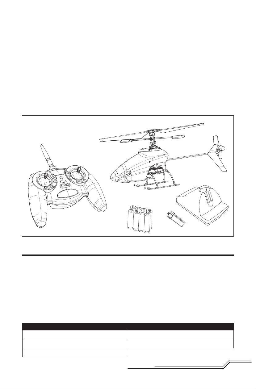
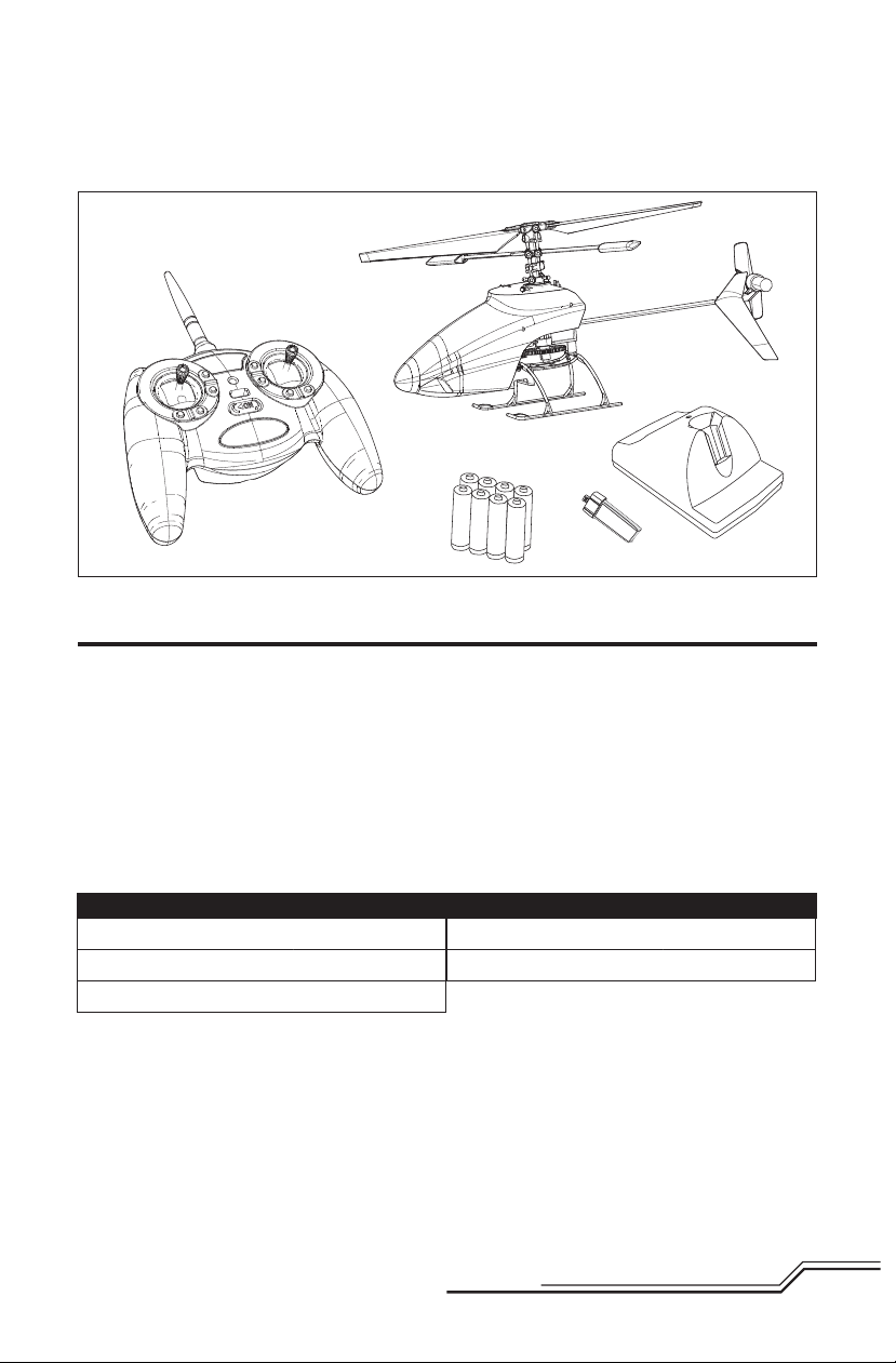
he Blade® mSR Ready-To-Fly helicopter is designed to bridge the gap between co-axial and high performance
T
ultra-micro helis. Co-axial heli pilots will appreciate the simplicity of the mSR with its proven design and
exceptional durability. Its unique rotor head provides the kind of response you would expect of a single-rotor heli,
but maintains a measure of positive stability similar to a co-axial heli. This blend of agility and stability makes it the
ideal “next step” for someone moving up from a coaxial heli, such as the
Blade CX2 or Blade mCX2.
Your Blade mSR RTF comes from the factory completely assembled and fl ight tested with everything you need to
get fl ying. This includes a 2.4GHz DSMX
and 8 AA batteries, 4 for the Li-Po charger and 4 for the transmitter. The mSR’s onboard 5-in-1 control unit combines the functions of a Spektrum™ 2.4GHz DSMX-compatible receiver, mixer, gyro, main and tail motor ESCs and
servos. This integration eliminates the need for diffi cult electronic installation and setup while providing heading
lock-like gyro performance and precise proportional motor and servo response.
While your mSR is ready-to-fl y right from the box, please take the time to read through this manual for tips on
battery safety and charging, control checks and more before making your fi rst fl ight. We also suggest viewing the
Instructional Video located on the Blade mSR product page at www.bladehelis.com
®
transmitter, a 150mAh 25C Li-Po fl ight battery, a convenient Li-Po charger
Table of Contents
Charging Warnings......................................................4
Low Voltage Cutoff (LVC) .............................................4
Battery Charging ......................................................... 5
First Flight Preparation ................................................5
Flying Checklist ..........................................................5
Transmitter and Receiver Binding ................................6
Transmitter Control ..................................................... 7
Installing the Flight Battery .........................................7
Understanding the Primary Flight Controls ..................8
Transmitter Dual Rates ...............................................9
Blade mSR Specifi cations
Length
Height
Main Rotor Diameter
190mm (7.5 in)
83mm (3.2 in)
180mm (7.0 in)
RTF
Flying the mSR ...........................................................9
Exploded View and Parts Listings .............................. 10
Optional Parts ...........................................................11
Troubleshooting Guide ..............................................12
Limited Warranty ......................................................13
Warranty and Service Contact Information ................14
Customer Service Information ................................... 14
FCC Information ........................................................ 15
Compliance Information
for the European Union .............................................15
Tail Rotor Diameter
Gross Weight
To register your product online, visit www.bladehelis.com
BLH3000
37mm (1.5 in)
31 g (1.1 oz)
3
EN
Page 4
Charging Warnings
The Battery Charger (EFLC1000) included with the
Blade mSR has been designed to safely charge the
Li-Po battery.
CAUTION: All instructions and warnings must be
followed exactly. Mishandling of Li-Po batteries
can result in a fi re, personal injury and/or property
damage.
• By handling, charging or using the included Li-Po
battery, you assume all risks associated with lithium
batteries.
• If at any time the battery begins to balloon or swell,
discontinue use immediately. If charging or discharging, discontinue and disconnect. Continuing to use,
charge or discharge a battery that is ballooning or
swelling can result in fi re.
• Always store the battery at room temperature in a
dry area for best results.
• Always transport or temporarily store the battery in
a temperature range of 40–120º F (5–49° C). Do not
store the battery or model in a car or direct sunlight.
If stored in a hot car, the battery can be damaged or
even catch fi re.
• Always charge batteries away from fl ammable
materials.
Low Voltage Cuto (LVC)
When a Li-Po battery is discharged below 3V, the battery may become damaged and may no longer accept a
charge. The mSR 5-in-1 control unit protects the fl ight
battery from over-discharge using Low Voltage Cutoff
(LVC). Before the battery charge decreases too much,
LVC reduces power supplied to the motor. Power to the
motor decreases and the LED on the 5-in-1 control unit
blinks, showing some battery power is reserved for
fl ight control and safe landing.
• Always inspect the battery before charging
• Always disconnect the battery after charging, and let
the charger cool between charges.
• Always constantly monitor the temperature of the
battery pack while charging.
• ONLY USE A CHARGER SPECIFICALLY DESIGNED TO
CHARGE LI-PO BATTERIES. Failure to charge the
battery with a compatible charger may cause a fi re
resulting in personal injury and/or property damage.
• Never discharge Li-Po cells to below 3V under load.
• Never cover warning labels with hook and loop
strips.
• Never leave charging batteries unattended.
• Never charge batteries outside recommended levels.
• Never charge damaged batteries.
• Never attempt to dismantle or alter the charger.
• Never allow minors to charge battery packs.
• Never charge batteries in extremely hot or cold
places (recommended between 40–120° F or
5–49° C) or place in direct sunlight.
When the motor power decreases, land the aircraft
immediately and recharge the fl ight battery.
Disconnect and remove the Li-Po battery from the
aircraft after use to prevent trickle discharge.Before
storage, charge the Li-Po battery to full capacity. During
storage, make sure battery charge does not fall below
3V.
NOTICE: Repeated fl ying to LVC may damage the
battery.
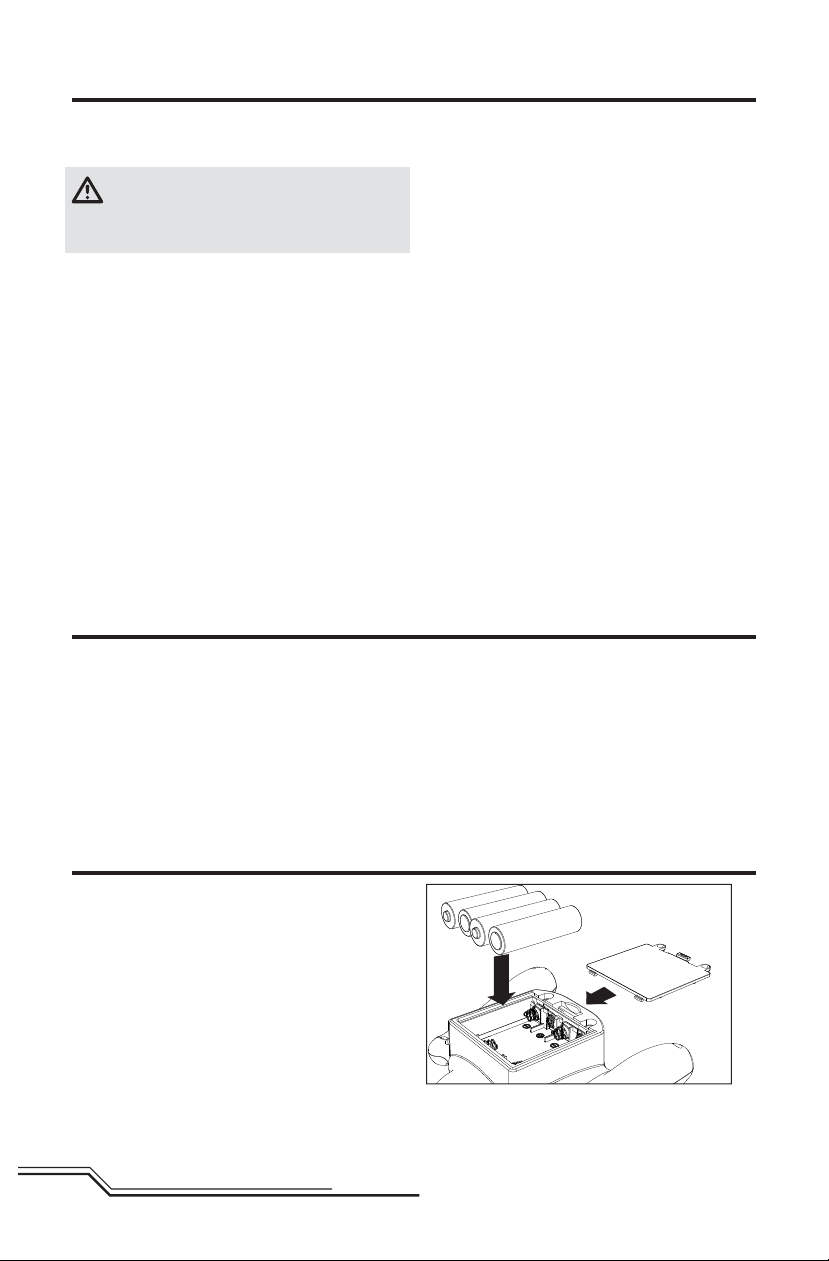
Installing the Transmitter Batteries
Install AA batteries into transmitter, noting polarity.
Replace the transmitter batteries when the power LED
fl ashes and the transmitter beeps.
EN
4
Page 5
Battery Charging
E-fl ite® 1-Cell 3.7V Rate 0.3A DC Li-Po Charger
(EFLC1000) Instructions:
1. Charge only batteries that are cool to the touch and
are not damaged. Look at the battery to make sure
it is not damaged e.g., swollen, bent, broken or
punctured.
2. Remove the cover on the bottom of the charger and
install four of the included AA batteries, noting proper
polarity. Replace the cover after the AA batteries are
installed.
3. Slide the battery into the slot on the charger. The end
cap of the battery is specifi cally designed to allow
the battery to fi t
into the slot one
way (usually with
the label on the
battery facing
outward) to
prevent reverse
polarity connection. However,
check for proper
alignment and
polarity before
proceeding to the
next step.
4. Gently press the battery and its connector into the
charge jack/connector located at the bottom of the
slot in the charger.
5. When you make the connection successfully, the LED
on the charger turns solid red, indicating charging
has begun.
6. Charging a fully discharged (not over-discharged)
150mAh battery takes approximately 20–30
minutes. As the battery nears full charge, the LED
begins to blink.
7. When the battery is fully charged, the LED blinks
approximately every 20 seconds or goes out entirely.
If the LED stays on when the battery is removed,
the AA batteries in the charger are low.
8. Always remove the battery from the charger immediately upon completion of charging.
NOTICE: Only use the included charger. For DC charger
operation (AA batteries): only use alkaline AA batteries
to power the charger. Do not use rechargable AA batteries.
WARNING: For AC operation, only use an
E-fl ite 6V power supply with this charger.
DO NOT use a 12V power supply or property damage
and injury could occur.
First Flight Preparation
❏ Remove and inspect contents
❏ Begin charging the fl ight battery
❏ Install four AA batteries in the transmitter
❏ Install the fl ight battery in the helicopter (once it
has been fully charged)
❏ Test the controls and motors
❏ Familiarize yourself with the controls
❏ Find a suitable area for fl ying
Flying Checklist
❏ Always turn the transmitter on fi rst
❏ Plug the fl ight battery into the lead from the
5-in-1 control unit
❏ Allow the 5-in-1 control unit to initialize and
arm properly
❏ Fly the model
❏ Land the model
❏ Unplug the fl ight battery from the 5-in-1
control unit
❏ Always turn the transmitter off last
5
EN
Page 6
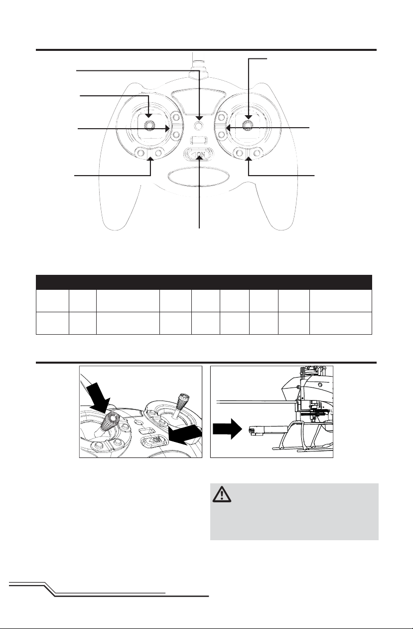
Transmitter Control
A
H
B
G
When pressed down, trim buttons make a sound that
increases or decreases in pitch at each pressing. The
E
tone in the pitch range of the sounds. The end of the
control range is sounded by a series of beeps.
C
DF
middle or neutral trim position is heard as a middle
H AB CDEFG H
Mode 1 Power
LED
Mode 2 Power
LED
Aileron (Left/Right)
Throttle (Up/Down)
Aileron (Left/Right)
Elevator (Up/Down)
Throttle
Trim
Elevator
Trim
Aileron
Trim
Aileron
Trim
ON/OFF
Switch
ON/OFF
Switch
Rudder
Trim
Rudder
Trim
Elevator
Trim
Throttle
Trim
Rudder (Left/Right)
Elevator (Up/Down)
Rudder (Left/Right)
Throttle (Up/Down)
Installing the Flight Battery
1
2
3
1. Lower the throttle to the lowest setting.
2. Power on the transmitter.
3. Install the battery in the helicopter by sliding it into
the battery mounting supports/slots just below the
main gears. Slide the battery into the slots with the
label facing downward and the connector oriented
toward the back of the helicopter.
4. Connect the battery cable to the
5-in-1 control unit.
EN
NOTICE: Do not allow the helicopter to move until the
blue LED on the 5-in-1 control unit turns solid.
CAUTION: Always disconnect the Li-Po battery
from the aircraft ESC when not fl ying to avoid
over-discharging the battery. Batteries discharged to
a voltage lower than the lowest approved voltage may
become damaged, resulting in loss of performance and
potential fi re when batteries are charged.
6
Page 7
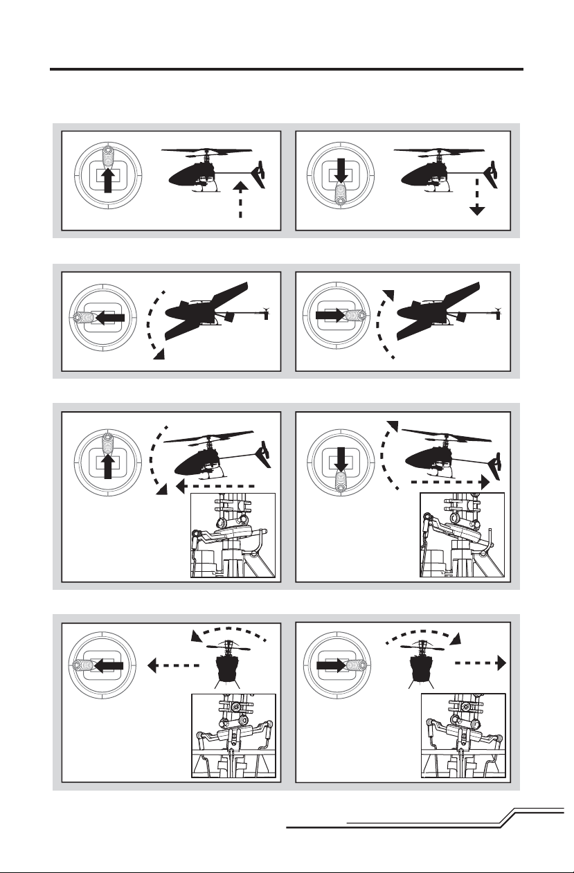
Understanding the Primary Flight Controls
If you are not familiar with the controls of your mSR, take a few minutes to familiarize yourself with them
before attempting your fi rst fl ight.
Throttle
Climb
Throttle up
Throttle down
Rudder
Nose Yaws Left
Rudder left Rudder right
Elevator
Forward
Elevator down
Side View
Elevator up
Descend
Nose Yaws Right
Backward
Side View
Aileron
Aileron left
Left
Rear View
7
Right
Aileron right
Rear View
EN
Page 8

Transmitter Dual Rates
®
Your Blade
controls (High and Low Rates) for aileron, elevator
and rudder. High Rates allow the helicopter controls to
reach their maximum values. Low Rates reduces the
control response (recommended for fi rst-time use).
When the transmitter is fi rst powered on it will be in the
high-rate mode. You can tell you are in the high-rate
mode when the LED on the transmitter glows solid red.
In the high-rate mode the controls are allowed to reach
their maximum values, which is typically preferred by
experienced pilots interested most in maximum control
authority.
By pushing in on the right-hand stick while in the highrate mode, you can enter the low-rate mode. You can
tell you are in the low-rate mode when the LED on the
transmitter blinks continuously. The low-rate mode is
typically preferred by (and best for) fi rst-time, low-time
and other pilots interested most in a reduced amount
of control that allows for smoother and more easily
controlled hovering and fl ying.
mSR transmitter features dual rate fl ight
Flying the mSR
Consult local laws and ordinances before choosing
a location to fl y your aircraft. Select a large, open
area away from people and objects. The Blade mSR
can be fl own indoors in a gymnasium, or outdoors in
light winds.
NOTICE: Please take a few minutes to familiarize yourself with the Blade mSR primary controls before
attempting your fi rst fl ight.
Takeo
Gradually increase throttle and allow the helicopter to
slowly increase the rotor head speed. Establish a hover
at least 18” (0.5 meter) high, outside of ground effect.
Flying
Avoid using excessive sub-trim or trim on aileron,
elevator and rudder. Setting trim can cause an unwanted drift or rotation of the helicopter.
NOTICE: You may be required to make slight trim
changes when switching back and forth between low
and high rates. The transmitter shortly beeps when
switching between the two rates.
Familiarize yourself with your mSR in low rate mode.
You may notice that the helicopter main shaft tilts to
the right and the helicopter has a slight right tilt in
fl ight. The right tilt counters the torque in fi xed pitch
helicopters and is normal.
NOTICE: Always fl y the helicopter with your back to the
sun to prevent loss of fl ight control.
Landing
Establish a hover at least 18” (0.5 meter) high, outside
of ground effect. Gradually lower the throttle until the
helicopter lands.
EN
8
Page 9

Transmitter and Receiver Binding
Binding is the process of programming the receiver of
the control unit to recognize the GUID (Globally Unique
Identifi er) code of a single specifi c transmitter.The
transmitter is bound to the model at the factory.
MLP4DSM Binding Procedure
1. Disconnect the fl ight battery from the helicopter.
2. Center all trims on your transmitter (refer to transmitter control section below for trim instructions).
3. Power off the transmitter and move the throttle stick to the down/off position.
4. Connect the fl ight battery in the helicopter. The LED on the 5-in-1 Control unit fl ashes after 5 seconds.
5. Push in on the left stick while powering on the transmitter
(you will hear a mechanical ‘click’ when pushing in the stick).
6. Release the left stick and immediately move it to the Low Throttle position. The transmitter will beep and the
power LED will blink.
7. The helicopter is bound when the blue LED on the 5-in-1 unit turns solid.
8. Disconnect the fl ight battery and power the transmitter off.
If you encounter problems, obey binding instructions
and refer to the troubleshooting guide for other
instructions.
To bind or re-bind your heli to your transmitter, please
follow the directions below:
If needed, contact the appropriate Horizon Product
Support offi ce. For a list of compatible DSM
ters, please visit www.bindnfl y.com.
®
transmit-
9
EN
Page 10
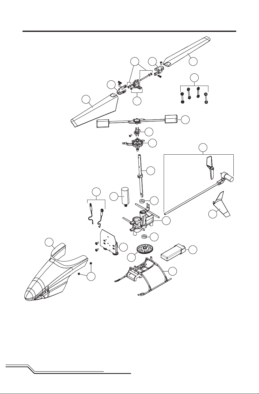
Exploded View and Parts Listings
P
O
P
R
J
E
S
N
L
K
I
B
G
B
C
H
R
Q
M
D
T
A
EN
U
F
10
Page 11
Part # Description
A EFLB1501S25
B EFLH2215
C EFLH3001
D EFLH3002
E EFLH3003
F EFLH3004
G EFLH3005
H EFLH3006 Main Gear: BMSR, MCP X
I EFLH3007
J EFLH3008
K EFLH3009
L EFLH3010
M EFLH3011 Mixing-Paddle Flybar: BMSR
N EFLH3012
150mAh 1S 3.7V 25C
LiPo Battery
Outershaft Bearing 3x6x2mm(2):
BMCX/2/MSR,FHX,MCP X
5-in-1 Control Unit,RX/Servos/
ESCs/Mixer/Gyro:BMSR
Tail Boom Assembly w/Tail
Motor/Rotor/Mount: BMSR
Coreless Main Motor
with/Pinion: BMSR
Landing Skid and Battery
Mount: BMSR
Main Frame with/Hardware:
BMSR
Carbon Fiber Main Shaft
w/Collar & Hardware: BMSR
Servo Pushrod Set
with/Ball Link (2): BMSR
Complete Precision
Swashplate: BMSR
Anti-Rotation Collar
with Hardware: BMSR
Main Rotor Hub
with/Hardware: BMSR
Part # Description
O EFLH3013
P EFLH3014
Q EFLH3015
R EFLH3016
S BLH3018
T BLH3020 Vertical Fin, Blue: BMSR
U EFLH3021
EFLH3022 Hardware Set: BMSR
EFLH1066
EFLH1067
EFLC1000
EFLH1064
EFLH3023
EFLH3024
Feathering Spindle w/O-Rings
and Bushings: BMSR
Main Blade Grips
with/Hardware: BMSR
Rotor Head Linkage Set (4):
BMSR
Main Rotor Blade Set
with/Hardware: BMSR
Complete Blue Canopy
with/Vertical Fin: BMSR
Canopy Mounting Grommets
(8):BMCX2/T,MSR,FHX,MH-35
Replacement Servo Mechanics:
Short Throw
Servo Retaining Collars: BMCX/2/
MSR,FHX,MH-35
1-Cell 3.7V 0.3A DC Li-Po
Charger
MLP4DSM 4-Channel Transmitter, 2.4GHz: BMCX/MSR
Carbon Fiber Training Gear Set:
BMCX/MSR
Precision Swashplate Calibration
Tool: BMSR
Optional Parts
Part # Description
EFLC1004
EFLC1005 AC to 6VDC 1.5-Amp Power Supply
EFLH3004GL
EFLH3005GL
EFLH3011GL
IMPORTANT: Due to the nature of the Glow In The Dark material, optional Glow In The Dark parts may not
be as durable as the original plastic parts.
Celectra™ 4-Port 1S 3.7V 0.3A DC
Li-Po Charger
Glow In The Dark Landing Skid &
Battery Mount:BMSR
Glow In The Dark Main Frame with/
Hardware: BMSR
Glow In The Dark Mixing Flybar:
BMSR
Part # Description
EFLH3016GL
EFLH3017GL Glow In The Dark Tail Rotor (1): BMSR
BLH3018R
EFLH3020GL Vertical Fin, Glow In The Dark: BMSR
BLH3020R Vertical Fin, Red: BMSR
EFLH3023
Glow In The Dark Main Rotor Blade
Set w/Hardware:BMSR
Complete Red Canopy with/Vertical
Fin: BMSR
Carbon Fiber Training Gear Set:
BMCX/MSR
11
EN
Page 12
Troubleshooting Guide
Problem Possible Cause Solution
Helicopter will not
initialize
Helicopter will not
spool up
Motor power decreases
during flight
Climb out rate is greatly
reduced
Poor tail authority
LED on receiver fl ashes
rapidly and aircraft will not
respond to transmitter
(during binding).
LED on receiver fl ashes
rapidly and aircraft will not
respond to transmitter
(after binding).
Helicopter vibrates or
shakes in fl ight
Helicopter spins
counter-clockwise in fl ight
Throttle at high position
On computer radios, switches not in
normal position
Throttle servo reversing improperly
confi gured
Low fl ight battery voltage Completely recharge fl ight battery
Receiver uses default soft Low
Voltage Cutoff (LVC)
Main gear has slipped on the main
shaft.
Tail boom is cracked Replace tail boom
The tail rotor blade is warped
or bent.
Aircraft not bound to transmitter Bind transmitter to aircraft receiver
Transmitter too near aircraft during
binding process
Less than a 5-second wait between
first powering on transmitter and
connecting flight battery to aircraft
Aircraft bound to different model
memory (ModelMatch™ radios
only)
Flight battery/Transmitter battery
charge is too low
Damaged rotor blades, spindle or
blade grips
Tail motor failing Replace the tail motor and tail boom
Reset controls with throttle stick at lowest position, and throttle trim at center or
lowest setting
Set flight mode to OFF/0 and switch
throttle hold off
Correct servo reversing
Refer to your transmitter manual
Recharge flight battery or replace flight
battery that is no longer performing. Replace charger batteries (included charger
only).
Push main gear back up into position.
Twist rotor blade back into position
or replace.
Power off transmitter, move transmitter a
larger distance from aircraft, disconnect
and reconnect flight battery to aircraft
and follow binding instructions.
Leaving transmitter on, disconnect and
reconnect flight battery to aircraft
Select correct model memory on transmitter and disconnect and reconnect
fl ight battery to aircraft
Replace/recharge batteries
Check main rotor blades and blade grips
for cracks or chips. Replace damaged
parts. Replace bent spindle.
EN
12
Page 13

Limited Warranty
What this Warranty Covers
Horizon Hobby, Inc., (Horizon) warrants to the original
purchaser that the product purchased (the “Product”) will
be free from defects in materials and workmanship at the
date of purchase.
What is Not Covered
This warranty is not transferable and does not cover (i)
cosmetic damage, (ii) damage due to acts of God, accident, misuse, abuse, negligence, commercial use, or due
to improper use, installation, operation or maintenance,
(iii) modification of or to any part of the Product, (iv)
attempted service by anyone other than a Horizon Hobby
authorized service center, (v) Product not purchased from
an authorized Horizon dealer, or (vi) Product not compliant
with applicable technical regulations.
OTHER THAN THE EXPRESS WARRANTY ABOVE, HORIZON
MAKES NO OTHER WARRANTY OR REPRESENTATION,
AND HEREBY DISCLAIMS ANY AND ALL IMPLIED
WARRANTIES, INCLUDING, WITHOUT LIMITATION,
THE IMPLIED WARRANTIES OF NON-INFRINGEMENT,
MERCHANTABILITY AND FITNESS FOR A PARTICULAR
PURPOSE. THE PURCHASER ACKNOWLEDGES THAT
THEY ALONE HAVE DETERMINED THAT THE PRODUCT
WILL SUITABLY MEET THE REQUIREMENTS OF THE
PURCHASER’S INTENDED USE.
Purchaser’s Remedy
Horizon’s sole obligation and purchaser’s sole and
exclusive remedy shall be that Horizon will, at its option,
either (i) service, or (ii) replace, any Product determined
by Horizon to be defective. Horizon reserves the right
to inspect any and all Product(s) involved in a warranty
claim. Service or replacement decisions are at the sole
discretion of Horizon. Proof of purchase is required for
all warranty claims. SERVICE OR REPLACEMENT AS
PROVIDED UNDER THIS WARRANTY IS THE PURCHASER’S
SOLE AND EXCLUSIVE REMEDY.
Limitation of Liability
HORIZON SHALL NOT BE LIABLE FOR SPECIAL, INDIRECT,
INCIDENTAL OR CONSEQUENTIAL DAMAGES, LOSS OF
PROFITS OR PRODUCTION OR COMMERCIAL LOSS IN
ANY WAY, REGARDLESS OF WHETHER SUCH CLAIM IS
BASED IN CONTRACT, WARRANTY, TORT, NEGLIGENCE,
STRICT LIABILITY OR ANY OTHER THEORY OF LIABILITY,
EVEN IF HORIZON HAS BEEN ADVISED OF THE
POSSIBILITY OF SUCH DAMAGES. Further, in no event
shall the liability of Horizon exceed the individual price of
the Product on which liability is asserted. As Horizon has
no control over use, setup, final assembly, modification
or misuse, no liability shall be assumed nor accepted for
any resulting damage or injury. By the act of use, setup
or assembly, the user accepts all resulting liability. If you
as the purchaser or user are not prepared to accept the
liability associated with the use of the Product, purchaser
is advised to return the Product immediately in new and
unused condition to the place of purchase.
Law
These terms are governed by Illinois law (without regard
to conflict of law principals). This warranty gives you
specific legal rights, and you may also have other rights
which vary from state to state. Horizon reserves the right
to change or modify this warranty at any time without
notice.
WARRANTY SERVICES
Questions, Assistance, and Services
Your local hobby store and/or place of purchase cannot
provide warranty support or service. Once assembly,
setup or use of the Product has been started, you must
contact your local distributor or Horizon directly. This will
enable Horizon to better answer your questions and service you in the event that you may need any assistance.
For questions or assistance, please visit our website
at www.horizonhobby.com, submit a Product Support
Inquiry, or call 877.504.0233 toll free to speak to a
Product Support representative.
Inspection or Services
If this Product needs to be inspected or serviced and is
compliant in the country you live and use the Product in,
please use the Horizon Online Service Request submission process found on our website or call Horizon to
obtain a Return Merchandise Authorization (RMA) number. Pack the Product securely using a shipping carton.
Please note that original boxes may be included, but are
not designed to withstand the rigors of shipping without
additional protection. Ship via a carrier that provides
tracking and insurance for lost or damaged parcels, as
Horizon is not responsible for merchandise until it arrives
and is accepted at our facility. An Online Service Request
is available at Horizon Hobby Service Center. If you do
not have internet access, please contact Horizon Product
Support to obtain a RMA number along with instructions
for submitting your product for service. When calling
Horizon, you will be asked to provide your complete
name, street address, email address and phone number
where you can be reached during business hours. When
sending product into Horizon, please include your RMA
number, a list of the included items, and a brief summary
of the problem. A copy of your original sales receipt must
be included for warranty consideration. Be sure your
name, address, and RMA number are clearly written on
the outside of the shipping carton.
Notice: Do not ship LiPo batteries to Horizon. If you
have any issue with a LiPo battery, please contact
the appropriate Horizon Product Support office.
Warranty Requirements
For Warranty consideration, you must include
your original sales receipt verifying the proof-ofpurchase date. Provided warranty conditions have been
met, your Product will be serviced or replaced free of
charge. Service or replacement decisions are at the sole
discretion of Horizon.
Non-Warranty Service
Should your service not be covered by warranty
service will be completed and payment will be
required without notification or estimate of the
expense unless the expense exceeds 50% of the
retail purchase cost. By submitting the item for service
you are agreeing to payment of the service without notification. Service estimates are available upon request. You
must include this request with your item submitted for
service. Non-warranty service estimates will be billed a
minimum of ½ hour of labor. In addition you will be billed
for return freight. Horizon accepts money orders and
cashier’s checks, as well as Visa, MasterCard, American
Express, and Discover cards. By submitting any item to
Horizon for service, you are agreeing to Horizon’s Terms
and Conditions found on our website Horizon Hobby
Service Center.
NOTICE: Horizon service is limited to Product
compliant in the country of use and ownership. If
non-compliant product is received by Horizon for
service, it will be returned unserviced at the sole
expense of the purchaser.
13
EN
Page 14
Warranty and Service Contact Information
Country of
Purchase
United States of
America
United Kingdom Horizon Hobby Limited
Germany
France Horizon Hobby SAS
China Horizon Hobby – China
Horizon Hobby Address Phone Number/Email Address
Horizon Service Center
(Electronics and engines)
Horizon Product Support
(All other products)
Horizon Technischer
Service
Customer Service Information
Country of
Purchase
United States
of America
United Kingdom Horizon Hobby Limited
Germany Horizon Hobby GmbH
Horizon Hobby Address Phone Number/Email Address
Sales
4105 Fieldstone Rd
Champaign, Illinois
61822 USA
4105 Fieldstone Rd
Champaign, Illinois
61822 USA
Units 1-4 Ployters Rd
Staple Tye
Harlow, Essex
CM18 7NS
United Kingdom
Christian-Junge-Straße 1
25337 Elmshorn
Germany
11 Rue Georges Charpak
77127 Lieusaint
Room 506, No. 97 Changshou
Rd. Shanghai, China 200060
4105 Fieldstone Rd
Champaign, Illinois
61822 USA
Units 1-4 Ployters Rd
Staple Tye
Harlow, Essex
CM18 7NS
United Kingdom
Christian-Junge-Straße 1
25337 Elmshorn
Germany
877-504-0233
Online Repair Request:
visit www.horizonhobby.com/service
877-504-0233
productsupport@horizonhobby.com
+44 (0) 1279 641 097
sales@horizonhobby.co.uk
+49 (0) 4121 2655 100
service@horizonhobby.de
+33 (0) 1 60 18 34 90
infofrance@horizonhobby.com
+86 (021) 5180 9868
info@horizonhobby.com.cn
(800) 338-4639
sales@horizonhobby.com
+44 (0) 1279 641 097
sales@horizonhobby.co.uk
+49 (0) 4121 2655 100
service@horizonhobby.de
France Horizon Hobby SAS
China Horizon Hobby – China
EN
11 Rue Georges Charpak
77127 Lieusaint
Room 506, No. 97 Changshou
Rd. Shanghai, China 200060
14
+33 (0) 1 60 18 34 90
infofrance@horizonhobby.com
+86 (021) 5180 9868
info@horizonhobby.com.cn
Page 15

FCC Information
This device complies with part 15 of the FCC rules.
Operation is subject to the following two conditions:
(1) This device may not cause harmful interference, and
(2) this device must accept any interference received,
including interference that may cause undesired
operation.
CAUTION: Changes or modifi cations not
expressly approved by the party responsible for
compliance could void the user’s authority to operate
the equipment.
This product contains a radio transmitter with wireless
technology which has been tested and found to be
compliant with the applicable regulations governing
a radio transmitter in the 2.400GHz to 2.4835GHz
frequency range.
Compliance Information for the European Union
Declaration of Conformity
(in accordance with ISO/IEC 17050-1)
No. HH20120828U1
Product(s): BLH mSR RTF
Item Number(s): BLH3000, BLH3000M1
Equipment class: 1
The object of declaration described above is in conformity with the requirements of the specifi cations listed below,
following the provisions of the European R&TTE directive 1999/5/EC, EMC Directive 2004/108/EC and LVD Directive
2006/95/EC:
EN 300-328 V1.7.1: 2006
EN 301 489-1 V1.7.1: 2006
EN 301 489-17 V1.3.2: 2008
EN61000-3-2:2006+A1:2009+A2:2009
EN61000-3-3:2008
EN60950-1:2006+A12: 2011
EN55022: 2010
EN55024: 2010
Signed for and on behalf of:
Horizon Hobby, Inc.
Champaign, IL USA
Aug 28, 2012
Executive Vice President and Chief Operating Offi cer
International Operations and Risk Management
Instructions for disposal of WEEE by users in the European Union
This product must not be disposed of with other waste. Instead, it is the user’s responsibility to dispose
of their waste equipment by handing it over to a designated collections point for the recycling of waste
electrical and electronic equipment. The separate collection and recycling of your waste equipment
at the time of disposal will help to conserve natural resources and make sure that it is recycled in a
manner that protects human health and the environment. For more information about where you can
drop off your waste equipment for recycling, please contact your local city offi ce, your household waste
disposal service or where you purchased the product.
15
Steven A. Hall
Horizon Hobby, Inc.
EN
Page 16
HINWEIS
Alle Anweisungen, Garantien und anderen zugehörigen Dokumente können im eigenen Ermessen von Horizon
Hobby, Inc. jederzeit geändert werden. Die aktuelle Produktliteratur fi nden Sie auf horizonhobby.com unter der
Registerkarte „Support“ für das betreffende Produkt.
Spezielle Bedeutungen
Die folgenden Begriffe werden in der gesamten Produktliteratur verwendet, um auf unterschiedlich hohe Gefahrenrisiken beim Betrieb dieses Produkts hinzuweisen:
HINWEIS: Wenn diese Verfahren nicht korrekt befolgt werden, können sich möglicherweise Sachschäden UND
geringe oder keine Gefahr von Verletzungen ergeben.
ACHTUNG: Wenn diese Verfahren nicht korrekt befolgt werden, ergeben sich wahrscheinlich Sachschäden UND
die Gefahr von schweren Verletzungen.
WARNUNG: Wenn diese Verfahren nicht korrekt befolgt werden, ergeben sich wahrscheinlich Sachschäden, Kollateralschäden und schwere Verletzungen ODER mit hoher Wahrscheinlichkeit oberfl ächliche Verletzungen.
WARNUNG: Lesen Sie die GESAMTE Bedienungsanleitung, um sich vor dem Betrieb mit den Produktfunktionen vertraut zu machen. Wird das Produkt nicht korrekt betrieben, kann dies zu Schäden am Produkt
oder persönlichem Eigentum führen oder schwere Verletzungen verursachen.
Dies ist ein hochentwickeltes Hobby-Produkt. Es muss mit Vorsicht und gesundem Menschenverstand betrieben
werden und benötigt gewisse mechanische Grundfähigkeiten. Wird dieses Produkt nicht auf eine sichere und
verantwortungsvolle Weise betrieben, kann dies zu Verletzungen oder Schäden am Produkt oder anderen
Sachwerten führen. Dieses Produkt eignet sich nicht für die Verwendung durch Kinder ohne direkte Überwachung
eines Erwachsenen. Versuchen Sie nicht ohne Genehmigung durch Horizon Hobby, Inc., das Produkt zu zerlegen,
es mit inkompatiblen Komponenten zu verwenden oder auf jegliche Weise zu erweitern. Diese Bedienungsanleitung enthält Anweisungen für Sicherheit, Betrieb und Wartung. Es ist unbedingt notwendig, vor Zusammenbau,
Einrichtung oder Verwendung alle Anweisungen und Warnhinweise im Handbuch zu lesen und zu befolgen, damit
es bestimmungsgemäß betrieben werden kann und Schäden oder schwere Verletzungen vermieden werden.
Nicht geeignet für Kinder unter 14 Jahren. Dies ist kein Spielzeug.
Zusätzliche Sicherheitsvorkehrungen und Warnhinweise
• Halten Sie stets in allen Richtungen einen Sicherhe-
itsabstand um Ihr Modell, um Zusammenstöße oder
Verletzungen zu vermeiden. Dieses Modell wird von
einem Funksignal gesteuert, das Interferenzen von
vielen Quellen außerhalb Ihres Einfl ussbereiches
unterliegt. Diese Interferenzen können einen augenblicklichen Steuerungsverlust verursachen.
• Betreiben Sie Ihr Modell immer auf einer Freifl äche
ohne Fahrzeuge in voller Größe, Verkehr oder Menschen.
• Befolgen Sie stets sorgfältig die Anweisungen und
Warnhinweise für das Modell und jegliche optionalen
Hilfsgeräte (Ladegeräte, Akkupacks usw.).
• Bewahren Sie alle Chemikalien, Klein- und Elektro-
teile stets außerhalb der Reichweite von Kindern auf.
• Setzen Sie Geräte, die für diesen Zweck nicht speziell
ausgelegt und geschützt sind, niemals Wasser aus.
Feuchtigkeit kann die Elektronik beschädigen.
• Stecken Sie keinen Teil des Modells in den Mund, da
dies zu schweren Verletzungen oder sogar zum Tod
führen kann.
DE
• Betreiben Sie Ihr Modell nie mit fast leeren Senderakkus.
• Halten Sie das Fluggerät immer in Sicht und unter
Kontrolle.
• Gehen Sie sofort auf Motor Aus bei Rotorberührung.
• Verwenden Sie immer vollständig geladene Akkus.
• Lassen Sie immer den Sender eingeschaltet wenn
das Fluggerät eingeschaltet ist.
• Nehmen Sie vor der Demontage des Fluggerätes die
Akkus heraus.
• Halten Sie bewegliche Teile immer sauber.
• Halten Sie die Teile immer trocken.
• Lassen Sie Teile immer erst abkühlen bevor Sie sie
anfassen.
• Nehmen Sie die Akkus/Batterien nach Gebrauch
heraus.
• Betreiben Sie Ihr Fluggerät niemals mit beschädigter
Verkabelung.
• Fassen Sie niemals bewegte Teile an.
16
Page 17
ielen Dank, dass Sie sich für den Blade® mSR entschieden haben. Neben geringerem Gewicht und besserer
V
Akkuleistung bietet der mSR einen stärkeren Hauptmotor und sowie einen starken Heckmotor, der beim Flug in
Hallen oder im Freien hervorragende Leistung und souveräne Hecksteuerung ermöglicht.
Lesen Sie sich dieses Handbuch vor dem ersten Flug gründlich durch. Es enthält wichtige Vorabinformationen,
diefüreinen erfolgreichen ersten Flug wichtig sind.
Inhaltverzeichnis
Warnhinweise und Vorgaben zum Akku .....................18
Niederspannungsabschaltung ................................... 18
Aufl aden der Akkus ...................................................19
Vorbereitung des ersten Fluges .................................19
Flug-Checkliste ......................................................... 19
Bindung von Sender und Empfänger .........................20
Sendersteuerung ...................................................... 21
Einlegen des Flugakkus ............................................21
Einführung in die Hauptsteuerfunktionen...................22
Dual Rates am Sender ..............................................23
Blade mSR Spezifi kationen
Länge
Höhe
Hauptrotordurchmesser
190mm
83mm
180mm
RTF
Flug des mSR ...........................................................23
Explosionszeichnung und Teileliste ............................ 24
Optionale Bauteile .....................................................25
Hilfestellung zur Problemlösung ................................ 26
Garantie und Service Informationen ..........................27
Garantie und Service Kontaktinformationen...............28
Kundendienstinformationen ......................................28
Rechtliche Informationen
für die Europäische Union .........................................29
Hecktrotordurchmesser
Gesamtgewicht
Besuchen Sie zur Produktregistrierung
www.bladehelis.com und bleiben damit immer
aktuell informiert.
BLH3000
37mm
31 g
17
DE
Page 18

Warnhinweise und Vorgaben zum Akku
Das dem Blade mSR beiliegende Akkuladegerät
(EFLC1000) wurde speziell auf eine sichere Aufl adung
des Li-Po-Akkus ausgelegt.
ACHTUNG: Alle Anweisungen und Warnungen
müssen exakt befolgt werden. Falscher Umgang
mit LiPo Akkus kann zu Feuer, Körperverletzung und/
oder Sachbeschädigung führen.
• Durch Handhaben, Aufl aden oder Verwenden des
inbegriffenen Li-Po-Akkus übernehmen Sie alle mit
Lithiumakkus verbundenen Risiken.
• Sollte der Akku beim Laden oder im Flug
beginnen, sich auszudehnen oder anzuschwellen
stoppen Sie den Ladevorgang oder den Flug unverzüglich. Wird mit dem Aufl aden oder Entladen eines
Akkus fortgefahren, der sich auszudehnen oder
anzuschwellen begonnen hat, kann dieses zu einem
Brand führen.
• Um beste Ergebnisse zu erzielen, lagern Sie den
Akku bei Raumtemperatur an einem trockenen Ort.
• Beim Transport oder vorübergehenden Lagern des
Akkus sollte der Temperaturbereich zwischen 5° C
und 49° C liegen. Bewahren Sie den Akku bzwdas
Modell nicht im Auto oder unter direkter Sonneneinstrahlung auf. Bei Aufbewahrung in einem heißen
Auto, kann der Akku beschädigt werden oder sogar
Feuer fangen.
• Laden Sie immer Li Po Akkus weit weg entfernt von
brennbaren Materialien.
• Überprüfen Sie immer den Akku vor dem Laden und
laden Sie niemals defekte oder beschädigte Akkus.
• Trennen Sie immer den Akku nach dem Laden und
lassen das Ladegerät abkühlen.
• Verwenden Sie ausschließlich ein Ladegerät das
speziell für das Laden von LiPo Akku geeignet ist.
Das Laden mit einem nicht geeignetem Ladegerät
kann Feuer und/oder Sachbeschädigung zur Folge
habe.
• VERWENDEN SIE NUR EIN SPEZIELL GEEIGNETES
LI-PO LADEGERÄT UM LI-PO AKKUS ZU LADEN.
Laden Sie den Akku mit einem nicht geeigneten
Ladegerät kann dieses zu Feuer, Personen- und
Sachschäden führen.
• Entladen Sie niemals ein LiPo Akku unter 3V pro
Zelle unter Last.
• Verdecken Sie niemals Warnhinweise mit Klettband.
• Lassen Sie niemals Akkus während des Ladens
unbeaufsichtigt.
• Laden Sie niemals beschädigte Akkus.
• Versuchen Sie nicht das Ladegerät zu demontieren
oder zu verändern.
• Lassen Sie niemals Minderjährige Akkus laden.
• Laden Sie niemals Akkus an extrem kalten oder
heißen Plätzen (empfohlener Temperaturbereich 5 49° C ) oder im direkten Sonnenlicht.
Niederspannungsabschaltung
Wenn ein Li-Po-Akku unter 3V pro Zelle entladen wird, kann er beschädigt werden und möglicherweise keine Ladung
mehr aufnehmen. Das 5-in-1-Steuergerät des mSR schützt den Flugakku mithilfe der Niederspannungsabschaltung
vor übermäßiger Entladung. Bevor die Akkuladung zu stark absinkt, reduziert die Niederspannungsabschaltung die
Stromzufuhr zum Motor. Die Stromversorgung des Motors nimmt ab, und die LED am 5-in-1-Steuergerät blinkt,
waszeigt, dass etwas Akkuladung für die Flugsteuerung und sichere Landung reserviert bleibt.
Wenn die Motorleistung abnimmt, landen Sie das Flugzeug sofort, und laden Sie den Flugakku neu auf.
Entnehmen Sie den Li-Po-Akku nach dem Flug aus dem Flugzeug, um eine allmähliche Selbstentladung zu
verhindern. Laden Sie den Li-Po-Akku vor der Lagerung vollständig auf. Stellen Sie während der Lagerung sicher,
dass die Ladung nicht unter 3V sinkt.
HINWEIS: Wenn Sie wiederholt bis zur Niederspannungsabschaltung fl iegen, wird der Akku beschädigt.
Einlegen der Senderbatterien
Legen Sie AA-Batterien unter Beachtung der korrekten
Polarität in den Sender ein. Wechseln Sie die Senderbatterien
aus, wenn die Ein/Aus-LED blinkt und der Sender einen
Signalton von sich gibt.
DE
18
Page 19

Aufl aden der Akkus
Anweisungen für das E-fl ite®-1-Zellen-3,7 V-0,3 AGleichstrom-Li-Po-Ladegerät mit variablem Ladestrom
(EFLC1000):
1. Laden Sie nur Akkus, die sich kühl anfühlen und
nicht beschädigt sind. SehenSie sich den Akku an,
um sicherzustellen, dass er nicht beschädigt ist, z.B.
angeschwollen oder verbogen ist oder Risse oder
Löcher aufweist.
2. Nehmen Sie den Deckel von der Unterseite des
Ladegeräts, und legen Sie vier der mitgelieferten
AA-Batterien unter Beachtung der richtigen Polarität
ein. Schließen Sie den Deckel wieder, wenn die AABatterien eingelegt sind.
3. Schieben Sie den Akku in das Fach im Ladegerät.
Die Endkappe des Akkus ist so ausgelegt, dass der
Akku nur in
einer Richtung
(in der Regel mit
dem Akkuetikett
nach außen) in
das Fach passt;
damit wird eine
falsche Polung
der Anschlüsse
vermieden.
Prüfen Sie
trotzdem, ob
Ausrichtung und
Polarität korrekt
sind, bevor Sie
mit dem nächsten Schritt fortfahren.
4. Drücken Sie den Akku und seinen Anschluss vorsichtig in die Ladebuchse unten im Ladegerätfach.
5. Ist der Akku korrekt eingesetzt, leuchtet die LED auf
dem Ladegerät kontinuierlich rot, was signalisiert,
dass der Ladevorgang begonnen hat.
6. Das Aufl aden eines vollständig entladenen (nicht
tiefentladenen) 150mAh-Akkus dauert ungefähr
20 bis 30Minuten. Wenn der Akku fast vollständig
aufgeladen ist, beginnt die LED zu blinken.
7. Wenn der Akku vollständig aufgeladen ist, blinkt die
LED ungefähr alle 20 Sekunden oder schaltet sich
ganz aus. Wenn die LED weiter leuchtet, nachdem
der Akku entnommen wurde, sind die AA-Batterien im Ladegerät zu schwach.
8. Entnehmen Sie den Akku immer sofort nach Abschluss des Ladevorgangs aus dem Ladegerät.
HINWEIS: Verwenden Sie ausschließlich das mitgelieferte Ladegerät. Zum Betrieb des Gleichstrom-Ladegeräts (AA-Batterien): Verwenden Sie zum Betrieb des
Ladegeräts ausschließlich AA-Alkalibatterien. AA-Akkus
dürfen nicht verwendet werden.
ACHTUNG: Schließen Sie KEINE Li-Po-Akkus
(ob aufgeladen oder entladen) an, wenn
das Netzteil an das Ladegerät, aber nicht an eine
Stromquelle angeschlossen ist. Sonst werden die Akkus
entladen und möglicherweise beschädigt.
Vorbereitung des ersten Fluges
❏ Entnehmen Sie den Packungsinhalt und
überprüfen Sie ihn auf etwaige Beschädigungen
❏ Beginnen Sie mit dem Aufl aden des Flugakkus
❏ Legen Sie vier AA-Batterien in den Sender ein
❏ Setzen Sie den Flugakku (nachdem er vollständig
aufgeladen wurde) in den Helikopter ein
❏ Testen Sie Steuerung und Motoren
❏ Machen Sie sich mit der Steuerung vertraut
❏ Suchen Sie sich einen geeigneten Platz zum Fliegen
Flug-Checkliste
❏ Schalten Sie immer zuerst den Sender ein
❏ Schließen Sie den Flugakku an das Kabel des
5-in-1-Steuergeräts an
❏ Lassen Sie das 5-in-1-Steuergerät ordnungsgemäß
initialisieren und scharfschalten
❏ Fliegen Sie das Modell
❏ Landen Sie das Modell
❏ Trennen Sie den Flugakku vom 5-in-1-Steuergerät
❏ Schalten Sie den Sender immer zuletzt aus
19
DE
Page 20

Sendersteuerung
A
H
B
G
Wenn die Trimmtasten gedrückt werden, geben sie
einen Signalton von sich, der bei jedem erneuten
Drücken höher oder tiefer wird.
E
Die mittlere oder neutrale Trimmstellung erklingt in
der mittleren Tonhöhe. An den äußeren Enden des
Steuerbereichs erklingt eine Tonfolge.
C
DF
H AB C DE F G H
Modus 1 Ein/Aus-
LED
Modus 2 Ein/Aus-
LED
Querruder
(links/rechts)
Gas (auf/ab)
Querruder
(links/rechts)
Höhenruder
(auf/ab)
Gas trimm Querruder-
Höhenrudertrimm
trimm
Querrudertrimm
EIN/AUSSchalter
EIN/AUSSchalter
Seitenrudertrimm
Seitenrudertrimm
Höhenrudertrimm
Gas trimm Seitenruder
Seitenruder
(links/rechts)
Höhenruder
(auf/ab)
(links/rechts)
Gas (auf/ab)
Einlegen des Flugakkus
1
2
3
1. Senken Sie den Gasgeber auf die niedrigste
Einstellung.
2. Schalten Sie den Sender ein.
3. Legen Sie den Akku in den Helikopter ein, indem
Sie ihn in die Akkuhalterung (Akkufach) unterhalb
des Hauptzahnrads schieben. Achten Sie dabei
darauf, dass die Beschriftung des Akkus nach
unten zeigt und der Stecker zum hinteren Teil des
Helikopters weist.
4. Schließen Sie das Akkukabel an das 5-in-1-
Steuergerät an.
DE
HINWEIS: Der Helikopter darf sich erst bewegen,
wenn die blaue LED am 5-in-1-Steuergerät kontinuierlich leuchtet.
ACHTUNG: Trennen Sie den Li-Po-Akku stets
vom ESC, wenn der Helikopter nicht fl iegt,
damit der Akkunicht zu stark entladen wird. Akkus, die
unter die angegebene Mindestspannung tiefentladen
werden, können beschädigt werden; Leistungseinbußen und brandgefahr beim Laden sind die Folge.
20
Page 21

Einführung in die Hauptsteuerfunktionen
Wenn Ihnen die Steuerung Ihres mSR noch nicht geläufi g ist, nehmen Sie sich bitte ein paar Minuten Zeit, umsich
mit ihr vertraut zu machen, bevor Sie Ihren ersten Flug versuchen.
Gasgeber
Gasgeber nach oben
Seitenruder
Seitenruder
nach links
Höhenruder
Höhenruder
nach unten
Seitenansicht
Querruder
Aufsteigen
Nase dreht nach links
Vorwärts
Gasgeber nach unten
Seitenruder
nach rechts
Höhenruder
nach oben
Seitenansicht
Sinken
Nase dreht nach rechts
Rückwärts
Querruder
nach links
Nach links
Rückansicht
21
Nach rechts
Querruder
nach rechts
Rückansicht
DE
Page 22

Dual Rates am Sender
Ihr Blade mSR Sender verfügt über Flugsteuerung mit
Dual Rates (hohe und niedrige Rate) für Quer-, Höhenund Seitenruder. Bei hoher Rate können die HelikopterBedienelemente ihre Maximalwerte erreichen. Bei
niedriger Rate reagiert der Helikopter schwächer auf die
Bedienelemente (für den ersten Flug empfohlen).
Wenn der Sender zum ersten Mal eingeschaltet wird,
befi ndet er sich im Modus für die hohe Rate. Den
Modus für die hohe Rate erkennen Sie daran, dass
die LED auf dem Sender kontinuierlich rot leuchtet. Im
Modus für die hohe Rate können die Bedienelemente
ihre Maximalwerte erreichen. Diese Einstellung wird
normalerweise von erfahrenen Piloten bevorzugt, die
maximale Kontrolle über die Steuerung haben möchten.
Wenn Sie im Modus für die hohe Rate auf den rechten
Knüppel drücken, schalten Sie in den Modus für die
niedrige Rate um. Den Modus für die niedrige Rate
erkennen Sie daran, dass die LED auf dem Sender
kontinuierlich blinkt. Der Modus für die niedrige
Rate wird normalerweise von Anfängern, Piloten,
die selten fl iegen, und anderen bevorzugt, die eine
weniger empfi ndliche Steuerung und damit ein
gleichmäßigeres und leichter kontrollierbares Schwebund Flugverhalten wünschen.
Flug des mSR
Informieren Sie sich über örtliche Gesetze und
Verordnungen, bevor Sie Ihr Flugzeug an einem
Ort fl iegen lassen. Wählen Sie einen großen, offenen
Bereich fern von Menschen und Objekten. Der Blade
mSR kann in einer Turnhalle oder bei leichtem Wind im
Freien gefl ogen werden.
HINWEIS: Nehmen Sie sich bitte ein paar Minuten Zeit,
um sich mit der Flugsteuerung des Blade mSR vertraut
zu machen, bevor Sie Ihren ersten Flug versuchen.
Start
Erhöhen Sie Gas und geben Sie dem Helikopter Zeit, die
Rotorkopfgeschwindigkeit zu erhöhen. Lassen Sie den
Helikopter mindestens einen halben Meter über dem
Boden schweben, außerhalb des Bodeneffekts.
Flug
Der Helikopter hebt vom Boden ab, wenn der Rotorkopf
ausreichend Geschwindigkeit erlangt. Lassen Sie den
Helikopter in geringer Höhe schweben und prüfen Sie,
ob er korrekt funktioniert. Vermeiden Sie übermäßigen
Subtrimm oder Trimm an Quer-, Höhen- und Seitenruder. Der Trimm kann unerwünschten Abdrift oder eine
Drehung des Helikopters verursachen.
Machen Sie sich mit Ihrem mSR im Modus mit niedriger Rate vertraut.
HINWEIS: Wenn Sie zwischen niedriger und hoher
Rate umschalten, müssen Sie möglicherweise die
Trimms geringfügig anpassen. Der Sender gibt beim
Umschalten der Rate einen kurzen Signalton von sich.
HINWEIS: Stehen Sie stets mit dem Rücken zur Sonne,
wenn Sie den Helikopter fl iegen, um einen Verlust der
Flugsteuerung zu vermeiden.
Landung
Lassen Sie den Helikopter mindestens einen halben
Meter über dem Boden schweben, außerhalb des
Bodeneffekts. Allmählich senken das Gas bis der
Helikopter landet.
DE
22
Page 23

Bindung von Sender und Empfänger
Die Bindung ist der Prozess, bei dem der Empfänger
des Steuergeräts darauf programmiert wird, den GUIDCode (global eindeutigen Kenncode) eines einzelnen,
spezifi schen Senders zu erkennen. Der Sender bereits
ab Werk an das Modellgebunden.
Bindungsvorgang für MLP4DSM
1. Trennen Sie den Flugakku vom Helikopter.
2. Zentrieren Sie alle Trimms an Ihrem Sender (Anweisungen zum Trimm fi nden Sie im Abschnitt zur
Sendersteuerung weiter unten).
3. Schalten Sie den Sender aus und senken Sie den Gasknüppel auf die Aus-Stellung.
4. Schließen Sie den Flugakku an den Helikopter an. Nach 5Sekunden beginnt die LED am 5-in-1-Steuergerät zu
blinken.
5. Drücken Sie fest auf den linken Knüppel und halten Sie ihn gedrückt, während Sie den Sender einschalten
(Sie hören einen mechanischen „Klick“, wenn Sie auf den Knüppel drücken).
6. Lassen Sie den linken Knüppel los und senken Sie den Gasgeber auf die niedrigste Einstellung. Der Sender
gibt einen Signalton von sich, und die Ein/Aus-LED blinkt.
7. Der Helikopter ist fertig gebunden, wenn die blaue LED am 5-in-1-Steuergerät kontinuierlich leuchtet.
8. Trennen Sie den Flugakku und schalten Sie den Sender aus.
Wenn Probleme auftreten, folgen Sie den Anweisungen
zur Bindung und lesen Sie die weiteren Anweisungen
im Abschnitt zur Fehlersuche. Falls erforderlich, wenden
Gehen Sie wie folgt vor, um Ihren Helikopter an
Ihren gewählten Sender zu binden oder die Bindung
erneutvorzunehmen:
Sie sich an das zuständige Horizon-Kundendienstbüro.
Eine Liste der kompatiblen DSM-Sender fi nden Sie auf
www.bindnfl y.com.
23
DE
Page 24

Explosionszeichnung und Teileliste
P
O
P
R
J
E
S
N
L
K
I
B
G
B
C
H
R
Q
M
D
T
A
DE
U
F
24
Page 25

Explosionszeichnung und Teileliste
Part # Description
A EFLB1501S25
B EFLH2215
C EFLH3001 Blade 5 in 1 Einheit: mSR
D EFLH3002
E EFLH3003
F EFLH3004
G EFLH3005 Chassis mit Kleinteilen: BMSR
H EFLH3006 Hauptzahnrad: BMSR, MCP X
I EFLH3007
J EFLH3008
K EFLH3009 Blade Taumelscheibe: mSR
L EFLH3010
M EFLH3011 Blade mSR Paddelstange: mSR
N EFLH3012 Blade Hauptrotorkopf: mSR
150mAh 1S 3.7V 25C
LiPo Akku
Blade Kugellager 3x6x2mm (2) :
BMCX/2/MSR, FHX, MCP X
Blade Heckausleger mit Motor
und Heckrotor : mSR
Blade Coreless Hauptmotor mit
Ritzel: mSR
Blade Landegestell mit Akkuaufnahme: mSR
Blade Carbon Hauptrotorwelle mit
Zubehör: mSR
Blade mSR Servoanlenkungen:
mSR
Blade Taumelscheibenführung:
mSR
Part # Description
O EFLH3013
P EFLH3014 Blade Blatthalter: mSR/ mSRX
Q EFLH3015 Rotorkopfanlenkungen (4): BMSR
R EFLH3016
S BLH3018
T BLH3020 Blade mSR Leitwerk blau: mSR
U EFLH3021
EFLH3022 Kleinteilsatz: BMSR
EFLH1066 Servomechanik
EFLH1067
EFLC1000
EFLH1064
EFLH3023 Trainingsgestell: BMCX/MSR
EFLH3024
Blattlagerwelle mit O-Ringen
und Buchsen: BMSR
Hauptrotorblätter mit Kleinteilen:
BMSR
Blade mSR Kabinenhaube blau:
mSR
Gummiringe zur Kabinenhaubenbefestigung (8):BMCX2/
T,MSR,FHX,MH-35
Blade Sicherung Servo:BMCX/
MSR
1-Zellen-3,7 V-0,3 A-Gleichstrom-Li-Po-Ladegerät
Blade MLP4DSM 4-Kanal-Sender, 2.4GHz: BMCX/MSR
Blade Einstelllehre Taumelscheibe:
mSR
Optionale Bauteile
Part # Description
EFLC1004
EFLC1005
EFLH3004GL
EFLH3005GL
EFLH3011GL
WICHTIG: Aufgrund der Materialeigenschaften der Glow in the Dark Komponenten sind diese nicht so
stabil wie die originalen Kunststoffteile.
E-fl ite E-fl ite 4 Port Ladegerät 1S
3;7V 0;3A
Netzadapter, Wechselstrom auf 6V
Gleichstrom 1,5A
Blade Glow in the Dark Landegestell:
mSR
Blade Glow in the Dark Hauptrahmen: mSR
Blade GLow in the Dark Paddelstange: mSR
Part # Description
EFLH3016GL
EFLH3017GL
BLH3018R Blade mSR Kabinenhaube rot: mSR
EFLH3020GL
BLH3020R Blade Leitwerk rot: mSR
EFLH3023 Blade Trainingsgestell Carbon: mSR
Blade Glow in the Dark Hauptrotorblätter: mSR
Blade Glow in the dark Heckrotorblätter : mSR
Blade Leitwerk Glow in the Dark:
mSR
25
DE
Page 26

Hilfestellung zur Problemlösung
Problem Mögliche Ursache Lösung
Gasgeber auf hoher Position
Helikopter initialisiert
sichnicht
Helikopter fährt nicht hoch Akkuladung zu niedrig
Motorleistung nimmt
während des Flugs ab
Steigrate ist erheblich
reduziert
Schlechte Hecksteuerung
LED am Empfänger blinkt
schnell, und Flugzeug
reagiert nicht auf den
Sender (bei der Bindung)
LED am Empfänger blinkt
schnell, und Flugzeug
reagiert nicht auf den
Sender (nach der Bindung)
Helikopter vibriert oder
zittert beim Flug
Hubschrauber dreht
während des Fluges gegen
den Uhrzeigersinn
An Computerfunkanlagen: Schalter
nicht auf normaler Position
Gasservoumkehrung falsch
konfi guriert
Empfänger führt eine
Niederspannungsabschaltung durch
Hauptzahnrad ist auf der
Hauptwelle verrutscht
Heckausleger hat Risse Wechseln Sie den Heckausleger aus
Heckrotorblatt ist verzogen
oderverbogen
Flugzeug nicht an Sender gebunden Binden Sie den Sender an
Sender war während des
Bindeprozesses zu nah am Flugzeug
Nach Einschalten des Senders
wurde nicht 5Sekunden lang
gewartet, bevor der Flugakku an
das Flugzeug angeschlossen wurde
Flugzeug an anderen
Modellspeicher gebunden
(nurModelMatch-Funkanlagen)
Ladung des Flugakkus oder der
Senderbatterien zu niedrig
Rotorblätter, Spindel oder Blatthalter
beschädigt
Heckmotor ausgefallen Ersetzen Sie den Heckrotor und Ausleger
Stellen Sie die Bedienelemente neu
ein, mit Gasknüppel auf der niedrigsten
Einstellung und Gastrimm in der Mitte
oder auf der niedrigsten Einstellung
Setzen Sie den Flugmodus auf OFF/0 und
schalten Sie Throttle-Hold aus
Korrigieren Sie die Servoumkehrung
Anweisungen in der Bedienungsanleitung
zum Sender
Laden Sie den Flugakku vollständig
wieder auf
Laden Sie den Flugakku auf, oder
wechseln Sie ihn aus, wenn seine
Leistung nicht mehr ausreicht
Drücken Sie das Hauptzahnrad wieder in
die richtige Position
Biegen Sie das Rotorblatt zurück in die
richtige Position oder wechseln Sie es aus
denFlugzeugempfänger
Schalten Sie den Sender aus, rücken Sie
ihn weiter vom Flugzeug ab, trennen Sie
den Flugakku, schließen Sie ihn wieder
an das Flugzeug an, und befolgen Sie die
Anweisungen zur Bindung
Lassen Sie den Sender eingeschaltet,
trennen Sie den Flugakku vom Flugzeug,
und schließen Sie ihn dann erneut an das
Flugzeug an
Wählen Sie den korrekten Modellspeicher
am Sender, trennen Sie den Flugakku
vom Flugzeug, und schließen Sie ihn dann
erneut an das Flugzeug an
Wechseln Sie die Batterien aus, oder laden
Sie den Akku auf
Prüfen Sie die Hauptrotorblätter und
Blatthalter auf Risse oder abgesplitterte
Stellen. Wechseln Sie beschädigte Teile
aus. Wechseln Sie die Spindel aus, wenn
sie verbogen ist.
DE
26
Page 27

Garantie und Service Informationen
Warnung
Ein ferngesteuertes Modell ist kein Spielzeug. Es
kann, wenn es falsch eingesetzt wird, zu erheblichen
Verletzungen bei Lebewesen und Beschädigungen
an Sachgütern führen. Betreiben Sie Ihr RC-Modell
nur auf freien Plätzen un beachten Sie alle Hinweise
der Bedienungsanleitung des Modells wie auch der
Fernsteuerung.
Garantiezeitraum
Exklusive Garantie ¬ Horizon Hobby Inc (Horizon)
garantiert, dass das gekaufte Produkt frei von
Material- und Montagefehlern ist. Der Garantiezeitraum
entspricht den gesetzlichen Bestimmung des Landes,
in dem das Produkt erworben wurde. In Deutschland
beträgt der Garantiezeitraum 6 Monate und der
Gewährleistungszeitraum 18 Monate nach dem
Garantiezeitraum.
Einschränkungen der Garantie
(a) Die Garantie wird nur dem Erstkäufer (Käufer)
gewährt und kann nicht übertragen werden. Der
Anspruch des Käufers besteht in der Reparatur
oder dem Tausch im Rahmen dieser Garantie. Die
Garantie erstreckt sich ausschließlich auf Produkte,
die bei einem autorisierten Horizon Händler erworben wurden.
Verkäufe an dritte werden von dieser Garantie
nicht gedeckt. Garantieansprüche werden nur
angenommen, wenn ein gültiger Kaufnachweis
erbracht wird. Horizon behält sich das Recht vor,
diese Garantiebestimmungen ohne Ankündigung zu
ändern oder modifizieren und widerruft dann bestehende Garantiebestimmungen.
(b) Horizon übernimmt keine Garantie für die
Verkaufbarkeit des Produktes, die Fähigkeiten und
die Fitness des Verbrauchers für einen bestimmten Einsatzzweck des Produktes. Der Käufer
allein ist dafür verantwortlich, zu prüfen, ob das
Produkt seinen Fähigkeiten und dem vorgesehenen
Einsatzzweck entspricht.
(c) Ansprüche des Käufers ¬ Es liegt ausschließlich im
Ermessen von Horizon, ob das Produkt, bei dem ein
Garantiefall festgestellt wurde, repariert oder ausgetauscht wird. Dies sind die exklusiven Ansprüche
des Käufers, wenn ein Defekt festgestellt wird.
Horizon behält sich vor, alle eingesetzten Komponenten
zu prüfen, die in den Garantiefall einbezogen werden
können. Die Entscheidung zur Reparatur oder zum
Austausch liegt nur bei Horizon. Die Garantie schließt
kosmetische Defekte oder Defekte, hervorgerufen
durch höhere Gewalt, falsche Behandlung des
Produktes, falscher Einsatz des Produktes, kommerziellen Einsatz oder Modifikationen irgendwelcher Art
aus. Die Garantie schließt Schäden, die durch falschen
Einbau, falsche Handhabung, Unfälle, Betrieb, Service
oder Reparaturversuche, die nicht von Horizon ausgeführt wurden aus. Rücksendungen durch den Käufer
direkt an Horizon oder eine seiner Landesvertretung
bedürfen der Schriftform.
Schadensbeschränkung
Horizon ist nicht für direkte oder indirekte
Folgeschäden, Einkommensausfälle oder kommerzielle Verluste, die in irgendeinem Zusammenhang
mit dem Produkt stehen verantwortlich, unabhängig
ab ein Anspruch im Zusammenhang mit einem
Vertrag, der Garantie oder der Gewährleistung erhoben werden. Horizon wird darüber hinaus keine
Ansprüche aus einem Garantiefall akzeptieren, die
über den individuellen Wert des Produktes hinaus
gehen. Horizon hat keinen Einfluss auf den Einbau,
die Verwendung oder die Wartung des Produktes
oder etwaiger Produktkombinationen, die vom Käufer
gewählt werden. Horizon übernimmt keine Garantie
und akzeptiert keine Ansprüche für in der folge auftretende Verletzungen oder Beschädigungen. Mit der
Verwendung und dem Einbau des Produktes akzeptiert
der Käufer alle aufgeführten Garantiebestimmungen
ohne Einschränkungen und Vorbehalte.
Wenn Sie als Käufer nicht bereit sind, diese
Bestimmungen im Zusammenhang mit der Benutzung
des Produktes zu akzeptieren, werden Sie gebeten,
dass Produkt in unbenutztem Zustand in der
Originalverpackung vollständig bei dem Verkäufer
zurückzugeben.
Sicherheitshinweise
Dieses ist ein hochwertiges Hobby Produkt und
kein Spielzeug. Es muss mit Vorsicht und Umsicht
eingesetzt werden und erfordert einige mechanische
wie auch mentale Fähigkeiten. Ein Versagen, das
Produkt sicher und umsichtig zu betreiben kann zu
Verletzungen von Lebewesen und Sachbeschädigungen
erheblichen Ausmaßes führen. Dieses Produkt ist
nicht für den Gebrauch durch Kinder ohne die Aufsicht
eines Erziehungsberechtigten vorgesehen. Die
Anleitung enthält Sicherheitshinweise und Vorschriften
sowie Hinweise für die Wartung und den Betrieb des
Produktes. Es ist unabdingbar, diese Hinweise vor der
ersten Inbetriebnahme zu lesen und zu verstehen. Nur
so kann der falsche Umgang verhindert und Unfälle mit
Verletzungen und Beschädigungen vermieden werden.
Fragen, Hilfe und Reparaturen
Ihr lokaler Fachhändler und die Verkaufstelle können eine Garantiebeurteilung ohne Rücksprache
mit Horizon nicht durchführen. Dies gilt auch für
Garantiereparaturen. Deshalb kontaktieren Sie in einem
solchen Fall den Händler, der sich mit Horizon kurz
schließen wird, um eine sachgerechte Entscheidung zu
fällen, die Ihnen schnellst möglich hilft.
Wartung und Reparatur
Muss Ihr Produkt gewartet oder repariert werden,
wenden Sie sich entweder an Ihren Fachhändler oder
direkt an Horizon.
Rücksendungen / Reparaturen werden nur mit einer
von Horizon vergebenen RMA Nummer bearbeitet.
Diese Nummer erhalten Sie oder ihr Fachhändler
vom technischen Service. Mehr Informationen
dazu erhalten Sie im Serviceportal unter www.
Horizonhobby.de oder telefonisch bei dem technischen
Service von Horizon.
27
DE
Page 28

Packen Sie das Produkt sorgfältig ein. Beachten Sie,
dass der Originalkarton in der Regel nicht ausreicht,
um beim Versand nicht beschädigt zu werden.
Verwenden Sie einen Paketdienstleister mit einer
Tracking Funktion und Versicherung, da Horizon bis
zur Annahme keine Verantwortung für den Versand
des Produktes übernimmt. Bitte legen Sie dem
Produkt einen Kaufbeleg bei, sowie eine ausführliche
Fehlerbeschreibung und eine Liste aller eingesendeten
Einzelkomponenten. Weiterhin benötigen wir die vollständige Adresse, eine Telefonnummer für Rückfragen,
sowie eine Email Adresse.
Garantie und Reparaturen
Garantieanfragen werden nur bearbeitet, wenn ein
Originalkaufbeleg von einem autorisierten Fachhändler
beiliegt, aus dem der Käufer und das Kaufdatum
hervorgeht. Sollte sich ein Garantiefall bestätigen wird
das Produkt repariert oder ersetzt. Diese Entscheidung
obliegt einzig Horizon Hobby.
Kostenpflichtige Reparaturen
Liegt eine kostenpflichtige Reparatur vor, erstellen wir
einen Kostenvoranschlag, den wir Ihrem Händler übermitteln. Die Reparatur wird erst vorgenommen, wenn
wir die Freigabe des Händlers erhalten. Der Preis für
die Reparatur ist bei Ihrem Händler zu entrichten. Bei
kostenpflichtigen Reparaturen werden mindestens 30
Minuten Werkstattzeit und die Rückversandkosten in
Rechnung gestellt.
Sollten wir nach 90 Tagen keine
Einverständniserklärung zur Reparatur vorliegen haben,
behalten wir uns vor, das Produkt zu vernichten oder
anderweitig zu verwerten.
Achtung: Kostenpflichtige Reparaturen nehmen wir
nur für Elektronik und Motoren vor. Mechanische
Reparaturen, besonders bei Hubschraubern und
RC-Cars sind extrem aufwendig und müssen
deshalb vom Käufer selbst vorgenommen werden.
Garantie und Service Kontaktinformationen
Land des Kauf Horizon Hobby Adresse Telefon/E-mail Adresse
Deutschland
Horizon Technischer
Service
Christian-Junge-Straße 1
25337 Elmshorn
Germany
+49 (0) 4121 2655 100
service@horizonhobby.de
Kundendienstinformationen
Land des Kauf Horizon Hobby Adresse Telefon/E-mail Adresse
Deutschland
Horizon Technischer
Service
Christian-Junge-Straße 1
25337 Elmshorn
Germany
+49 (0) 4121 2655 100
service@horizonhobby.de
DE
28
Page 29

Rechtliche Informationen für die Europäische Union
Konformitätserklärung
Konformitätserklärung laut Allgemeine Anforderungen (ISO/IEC 17050-1:2004, korrigierte Fassung 2007-06-15);
Deutsche und Englische Fassung EN ISO/IEC 17050-1:2010
Declaration of conformity (in accordance with ISO/IEC 17050-1)
No. HH20120828U1
Horizon Hobby GmbH
Hamburger Straße 10
D-25337 Elmshorn
erklärt das Produkt: BLH mSR RTF BLH3000, BLH3000M1
declares the product: BLH mSR RTF BLH3000, BLH3000M1
Geräteklasse: 1
equipment class: 1
den grundleegenden Andforderungen des §3 und den übrigen einschlägigen Bestimmungen des FTEG (Artikel 3 der
R&TTE) und EMV Directive 2004/108/EC und LVD 2006/95/EC entspricht.
complies with the essential requirements of §3 and other relevant provisions of the FTEG (Article 3 of the R&TTE
directive) and EMC Directive 2004/108/EC and LVD Directive 2006/95/EC.
Angewendete harmonisierte Normen:
Harmonized standards applied:
EN 300-328 V1.7.1: 2006
EN 301 489-1 V1.7.1: 2006
EN 301 489-17 V1.3.2: 2008
EN61000-3-2:2006+A1:2009+A2:2009
EN61000-3-3:2008
EN60950-1:2006+A12: 2011
EN55022: 2010
EN55024: 2010
Steven A. Hall
Elmshorn,
28 August 2012
Horizon Hobby GmbH; Christian-Junge-Straße 1, 25337 Elmshorn
HR Pi: HRB 1909; UStIDNr.:DE812678792; Str.Nr.: 1829812324
Geschäftsführer: Birgit Schamuhn, Steven A. Hall Tel.: +49 (0) 4121 2655 100 Fax: +49 (0) 4121 2655 111
eMail: info@horizonhobby.de; Internet: www.horizonhobby.de Es gelten unsere allgemeinen Geschäftsbedingungen,
die in unseren Geschäftsräumen eingesehen werden können. Ware bleibt bis zur vollständigen Bezahlung Eigentum der Horizon Hobby GmbH
Geschäftsführer
Managing Director
Birgit Schamuhn
Geschäftsführerin
Managing Director
Anweisungen zur Entsorgung von Elektro- und Elektronik-Altgeräten für Benutzer
in der Europäischen Union
Dieses Produkt darf nicht zusammen mit anderem Abfall entsorgt werden. Stattdessen ist der Benutzer dafür verantwortlich, unbrauchbare Geräte durch Abgabe bei einer speziellen Sammelstelle für
das Recycling von unbrauchbaren elektrischen und elektronischen Geräten zu entsorgen. Die separate Sammlung und das Recycling von unbrauchbaren Geräten zum Zeitpunkt der Entsorgung hilft,
werden, bei der die menschliche Gesundheit und die Umwelt geschützt werden. Weitere Informationen dazu, wo
Sie unbrauchbare Geräte zum Recycling abgeben können, erhalten Sie bei lokalen Ämtern, bei der Müllabfuhr für
Haushaltsmüll sowie dort, wo Siedas Produkt gekauft haben.
natürliche Ressourcen zu bewahren und sicherzustellen, dass Geräte auf eine Weise wiederverwertet
29
DE
Page 30

REMARQUE
La totalité des instructions, garanties et autres documents est sujette à modifi cation à la seule discrétion
d’Horizon Hobby, Inc. Pour obtenir la documentation àjour, rendez-vous sur le site horizonhobby.com et cliquez
sur l’onglet de support de ce produit.
Signifi cation de certains termes spécifi ques
Les termes suivants sont utilisés dans l’ensemble du manuel pour indiquer différents niveaux de danger lors de
l’utilisation de ce produit:
REMARQUE: procédures qui, si elles ne sont pas suivies correctement, peuvent entraîner des dégâts matériels
ET éventuellement un faible risque de blessures.
ATTENTION: procédures qui, si elles ne sont pas suivies correctement, peuvent entraîner des dégâts matériels
ET des blessures graves.
AVERTISSEMENT: procédures qui, si elles ne sont pas suivies correctement, peuvent entraîner des dégâts
matériels et des blessures graves OU engendrer une probabilité élevée de blessure superfi cielle.
AVERTISSEMENT: lisez la TOTALITÉ du manuel d’utilisation afi n de vous familiariser avec les caractéristiques du produit avant de le faire fonctionner. Une utilisation incorrecte du produit peut entraîner sa
détérioration, ainsi que des risques de dégâts matériels, voire de blessures graves.
Ceci est un produit de loisirs sophistiqué. Il doit être manipulé avec prudence et bon sens et requiert des
aptitudes de base en mécanique. Toute utilisation irresponsable de ce produit ne respectant pas les principes
de sécurité peut provoquer des blessures, entraîner des dégâts matériels et endommager le produit. Ce produit
n’est pas destiné à être utilisé par des enfants sans la surveillance directe d’un adulte. N’essayez pas de
démonter le produit, de l’utiliser avec des composants incompatibles ou d’en améliorer les performances sans
l’accord d’Horizon Hobby, Inc. Ce manuel comporte des instructions relatives à la sécurité, au fonctionnement et
à l’entretien. Il est capital de lire et de respecter la totalité des instructions et avertissements du manuel avant
l’assemblage, le réglage et l’utilisation, ceci afi n de manipuler correctement l’appareil et d’éviter tout dégât
matériel ou toute blessure grave.
14 ans et plus. Ceci n’est pas un jouet.
Précautions et avertissements supplémentaires liés à la sécurité
• Maintenez toujours une distance de sécurité
adéquate dans toutes les directions autour de votre
modèle afi n d’éviter les collisions et blessures.
Ce modèle est contrôlé par un signal radio, qui
peut être soumis à des interférences provenant de
nombreuses sources que vous ne maîtrisez pas. Les
interférences sontsusceptibles d’entraîner une perte
de contrôle momentanée.
• Faites toujours fonctionner votre modèle dans des
espaces dégagés, à l’écart des véhicules, de la
circulation et des personnes.
• Respectez toujours scrupuleusement les instructions et avertissements relatifs à votre modèle et à
tous les équipements complémentaires optionnels
utilisés(chargeurs, packs de batteries rechargeables,
etc.).
• Tenez toujours tous les produits chimiques, les
petites pièces et les composants électriques hors de
portée des enfants.
• Évitez toujours d’exposer à l’eau tout équipement
non conçu et protégé à cet effet. L’humidité endommage les composants électroniques.
FR
• Ne mettez jamais aucune partie du modèle dans
votre bouche. Vous vous exposeriez à un risque de
blessure grave, voire mortelle.
• Ne faites jamais fonctionner votre modèle lorsque les
batteries de l’émetteur sont faibles.
• Toujours conserver le modèle réduit en vue et sous
contrôle.
• Toujours baisser le manche des gaz lorsque les pales
touchent un objet ou le sol.
• Toujours utiliser des batteries complètement
chargées.
• Toujours conserver l’émetteur allumé lorsque le
modèle est sous tension.
• Toujours retirer les batteries avant démontage.
• Toujours conserver les parties mobiles propres.
• Toujours conserver le modèle au sec.
• Toujours laisser refroidir les pièces telles le moteur,
après utilisation, avant de les toucher.
• Toujours retirer la batterie après utilisation.
• Ne jamais utiliser le modèle si des fi ls électriques ou
pièces sont endommagés.
• Ne jamais toucher les pièces en mouvement.
30
Page 31

ous vous remercions d’avoir acheté l’hélicoptère Blade mSR! Outre un poids plus faible et une batterie plus
N
performante, lemodèle mSR est équipé d’un moteur principal et d’un moteur de queue plus puissants pour des
performances accrues et une réactivité améliorée de la queue que vous voliez à l’intérieur ou à l’extérieur.
Prenez le temps de lire ce manuel de A à Z avant de vous lancer dans l’aventure de ce premier vol. Ce manuel
contient des informations importantes qui vous aideront à faire de votre premier vol une expérience exceptionnelle.
Table des matières
Mises en garde relatives au chargement ................... 32
Coupure par tension faible ........................................32
Charge des Batteries ................................................33
Préparation au premier vol ........................................ 33
Check-list de vol ....................................................... 33
Affectation de l’émetteur et du récepteur ..................34
Contrôle de l’émetteur ..............................................35
Installation de la batterie de vol ................................35
Compréhension des commandes de vol de base ....... 36
Doubles débattements de l’émetteur ........................37
Spécifi cations du Blade mSR
Longueur
Hauteur
Diamètre du rotor principal
190mm
83mm
180mm
RTF
Faire voler le mSR ..................................................... 37
Vue éclatée et liste des pièces détachées .................38
Pièces optionnelles ...................................................39
Guide de résolution des problèmes
de fonctionnement .................................................... 40
Garantie et réparations .............................................41
Coordonnées de Garantie et réparations ...................42
Informations de contact pour les pièces ....................42
Informations de conformité
pour l’Union européenne ........................................... 43
Diamètre du rotor de queue
Poids brut
Pour enregistrer votre produit en ligne, veuillez visiter
www.bladehelis.com
BLH3000
37mm
31 g
31
FR
Page 32

Mises en garde relatives au chargement
Le chargeur de batterie (EFLC1000) fourni avec le
Blade mSR a été spécialement conçu pour charger en
toute sécurité la batterie Li-Po incluse.
ATTENTION: les instructions et avertissements
doivent être scrupuleusement suivis. Une
manipulation non-appropriée des batteries Li-Po peut
provoquer un incendie, des blessures corporelles et/ou
des dégâts matériels.
• En manipulant, en chargeant ou en utilisant la bat-
terie Li-Po incluse, vous assumez tous les risques
associés aux batteries au lithium.
• Si la batterie commence à gonfl er ou à se dilater,
cessez immédiatement de l’utiliser. Si vous étiez en
train de la charger ou de la décharger, interrompez
la procédure et déconnectez-la. Continuer à utiliser,
charger ou décharger une batterie qui gonfl e ou se
dilate peut provoquer un incendie.
• Pour obtenir les meilleurs résultats, entreposez
toujours la batterie à température ambiante, dans un
endroit sec.
• Lorsque vous transportez la batterie ou que vous
la stockez temporairement, la température doit
toujours être comprise entre 5 et 49 ºC.
• Ne stockez en aucun cas la batterie ou l’hélicoptère
dans une voiture ou à un endroit directement exposé
à la lumière du soleil. Laissée dans une voiture
chaude, la batterie peut se détériorer ou même
prendre feu.
• Chargez toujours les batteries à distance de tout
matériau infl ammable.
• Faites toujours l’inspection de la batterie avant la
charge, et ne chargez jamais des batteries hors
d’usage ou endommagées.
• Déconnectez toujours la batterie après la charge, et
laissez le chargeur se refroidir entre les charges.
• Surveillez toujours en continu la température du
pack de batteries au cours de la charge.
• UTILISEZ EXCLUSIVEMENT UN CHARGEUR CONÇU
SPÉCIFIQUEMENT POUR CHARGER DES BATTERIES LI-PO. Le fait de charger la batterie avec un
chargeur non compatible peut être à l’origine d’un
incendie provoquant des blessures corporelles et/ou
des dégâts matériels.
• Ne déchargez jamais les cellules Li-Po en dessous
de 3 V.
• Ne couvrez jamais les étiquettes d’avertissement
avec des bandes auto-agrippantes.
• Ne laissez jamais sans surveillance des batteries en
cours de charge.
• Ne chargez jamais les batteries sans respecter les
niveaux recommandés.
• N’essayez jamais de démonter ou de modifi er le
chargeur.
• Ne laissez jamais des mineurs charger des packs
de batteries.
• Ne chargez jamais les batteries dans des endroits
extrêmement chauds ou froids (la plage de températures recommandées se situe entre 5 et 49 °C) et ne
les exposez jamais à la lumière directe du soleil.
Coupure par tension faible
Quand une batterie Li-Po est déchargée en dessous de 3V, elle est endommagée et ne peut pas maintenir de
charge. L’unité de contrôle 5 en 1 du mSR protège la batterie de vol d’une décharge excessive en utilisant le
processus de coupure par tension faible. Avant que la charge de la batterie ne devienne trop faible, ce processus
réduit l’alimentation du moteur. L’alimentation du moteur diminue et augmente rapidement et la DEL sur l’unité de
contrôle 5 en 1 clignote, ce qui indique qu’une partie de la puissance de la batterie est réservée pour commander
le vol et assurer l’atterrissage.
Quand cela se produit, faites immédiatement atterrir l’avion et rechargez la batterie de vol.
Déconnectez la batterie Li-Po de l’avion et retirez-la après utilisation pour éviter toute décharge lente de la batterie.
Chargez complètement votre batterie Li-Po avant de l’entreposer. Au cours du stockage, assurez-vous que la charge
de la batterie ne descend pas sous les 3V.
REMARQUE: Des vols répétés avec coupure par tension faible endommageront la batterie.
Installation des batteries de l’émetteur
Installez les batteries AA dans l’émetteur, notant la polarité
(RTF seul). Remplacez les batteries de l’émetteur lorsque le
voyant d’alimentation de l’émetteur clignote et que l’émetteur
émet un bip.
FR
32
Page 33

Charge des Batteries
Instructions pour le chargeur Li-Po CC 0,3A à vitesse
variable 3,7V 1élément E-fl ite® :
1. Ne chargez que des batteries froides au toucher et
non endommagées. Examinez la batterie pour vous
assurer qu’elle n’est pas endommagée et notamment qu’elle n’est pas dilatée, déformée, cassée ou
perforée.
2. Retirez le cache situé sous le chargeur et installez
quatre des batteries AA fournies, en respectant leur
polarité. Remettez le cache en place après avoir
installé les batteries AA.
3. Faites glisser la batterie dans la fente du chargeur.
L’extrémité de la batterie est spécifi quement conçue
pour permettre
à celle-ci de
rentrer dans
la fente dans
un seul sens
(habituellement
avec l’étiquette
vers l’avant), ceci
afi n d’empêcher
une inversion de
polarité. Vérifi ez
néanmoins que
l’alignement et
la polarité sont
corrects avant de
poursuivre.
4. Introduisez doucement la batterie et son connecteur
dans le connecteur de charge situé en bas de la
fente du chargeur.
5. Lorsque la connexion est effectuée correctement, la
DEL du chargeur passe au rouge fi xe, indiquant que
la charge a commencé.
6. La charge d’une batterie 150mAh complètement
déchargée (sans l’avoir été de manière excessive)
requiert de20 à 30minutes environ. Lorsque la
charge est presque complète, la DEL commence à
clignoter.
7. Lorsque la batterie est complètement chargée, la
DEL clignote toutes les 20secondes environ ou
s’éteint. SilaDEL reste allumée lorsque la bat-
terie est retirée, cela signifi e que les batteries AA
se trouvant dansle chargeur sont faibles.
8. Débranchez systématiquement la batterie du
chargeur immédiatement après la fi n du processus
de charge.
REMARQUE: Utilisez uniquement le chargeur fourni.
Pour faire fonctionner le chargeur CC (batteries AA):
utilisez uniquement des batteries alcalines AA pour
alimenter le chargeur. N’utilisez pas de batteries
rechargeables.
ATTENTION: NE CONNECTEZ PAS de batteries
Li-Po chargées ou déchargées si l’alimentation
est connectée au chargeur alors qu’elle n’est pas
raccordée à une source de courant. Vous risquez
dedécharger et d’endommager les batteries.
Préparation au premier vol
❏ Retirez le contenu de la boîte et inspectez-le
❏ Commencez à charger la batterie de vol
❏ Installez les quatre batteries AA restantes dans
l’émetteur
❏ Installez la batterie de vol dans l’hélicoptère
(après l’avoir complètement chargée)
❏ Testez les commandes et les moteurs (voir page 14)
❏ Familiarisez-vous avec les commandes
❏ Trouvez une zone adaptée au vol
Check-list de vol
❏ Allumez toujours l’émetteur en premier
❏ Branchez la batterie de vol sur la prise de l’unité
de contrôle 5 en 1
❏ Laissez l’unité de contrôle 5 en 1 s’initialiser et
s’armer correctement
❏ Faites voler le modèle
❏ Faites-le atterrir
❏ Débranchez la batterie de vol du module de
contrôle 5 en 1
❏ Eteignez toujours l’émetteur en dernier
33
FR
Page 34

Contrôle de l’émetteur
A
H
B
G
Lorsqu’ils sont enfoncés, les boutons de trim font un
bruit qui augmente ou diminue en intensité àchaque
E
utilise une tonalité de milieu de gamme. Une série de
bips sonores indique la fi n de la plage de contrôle.
C
DF
pression. La position intermédiaire ou neutre du trim
H ABCDEFGH
Mode 1 DEL
d’alimentation
Mode 2 DEL
d’alimentation
Aileron
(Gauche/Droit)
Gaz (Haut/Bas)
Aileron
(Gauche/Droit)
Gouverne de
direction (Haut/Bas)
Trim des
gaz
Trim de
profondeur
Trim
d’aileron
Trim
d’aileron
Commutateur
ON/OFF
Commutateur
ON/OFF
Trim de
gouvernail
Trim de
gouvernail
Trim de
profondeur
Trim des
gaz
Gouverne de direction (Gauche/Droit)
Gouverne de
direction (Haut/Bas)
Gouverne de direction (Gauche/Droit)
Gaz (Haut/Bas)
Installation de la batterie de vol
1
2
3
1. Abaissez la manette des gaz jusqu’à son réglage
le plus bas.
2. Allumez l’émetteur.
3. Placez la batterie dans l’hélicoptère en la glissant
dans les supports/fentes situés juste en dessous
de la transmission principale. Faites glisser la
batterie dans les fentes, l’étiquette étant orientée
vers le bas et le connecteur vers l’arrière de
l’hélicoptère.
4. Connectez le câble de la batterie sur l’unité de
contrôle 5 en 1.
FR
REMARQUE: Ne permettez pas à l’hélicoptère de
bouger tant que la DEL bleue sur l’unité de contrôle 5
en 1 ne reste pas allumée.
ATTENTION: Déconnectez toujours la batterie
Li-Po de l’ESC de l’hélicoptère lorsque celui-ci
ne vole paspour éviter qu’elle ne se décharge excessivement. Des batteries déchargées à une tension
inférieureàla tension la plus faible autorisée risquent
d’être endommagées, ce qui se traduit par des performances réduites et un risque d’incendie lorsqu’elles
sont chargées.
34
Page 35

Compréhension des commandes de vol de base
Si vous n’avez pas encore bien assimilé les commandes de votre mSR, prenez quelques minutes pour vous familiariser avec elles avant de tenter votre premier vol.
Throttle (Gaz)
Monter
Gouverne de direction
Le nez tourne
Gouverne de
direction à gauche
vers la gauche
Gouverne de profondeur
Vers l’avant
Gouverne de
profondeur baissée
Vue latérale
Réduire les gazAugmenter les gaz
Gouverne de
direction à droite
Gouverne de
profondeur levée
Vue latérale
Descendre
Le nez tourne
vers la droite
Vers l’arrière
Aileron
Aileron à gauche
Gauche
Vue arrière
35
Droite
Aileron à droite
Vue arrière
FR
Page 36

Doubles débattements de l’émetteur
Votre émetteur Blade mSR est équipé de commandes de
vol àdouble débattement (grands et petits débattements)
pour l’aileron, la gouverne de profondeur et la gouverne
de direction. Lesgrands débattements permettent
aux commandes de l’hélicoptère d’atteindre leurs
valeurs maximales. Les petits débattements diminuent
la réponse des commandes (recommandés pour la
première utilisation).
Lorsque l’émetteur est allumé pour la première fois, il
est automatiquement en mode grands débattements.
Vous savez que vous êtes en mode grands débattements lorsque la DEL de l’émetteur est rouge fi xe. En
mode grands débattements, lescommandes peuvent
atteindre leurs valeurs maximales, ce que préfèrent
typiquement les pilotes expérimentés désirant un
maximum de réactivité des commandes.
Enfoncez la manette droite lorsque vous êtes en mode
grands débattements pour passer en mode petits
débattements. Vous savez que vous êtes en mode
petits débattements lorsque la DEL de l’émetteur
clignote en permanence. Le mode petits débattements
Faire voler le mSR
Consultez les lois et règlements locaux avant de
choisir un emplacement pour faire voler votre
avion. Choisissez une zone relativement grande et
bien dégagée où il n’y a personne et sans obstacles. Le
Blade mSR peut voler à l’intérieur, dans un gymnase ou
à l’extérieur si le vent est faible.
REMARQUE: Prenez quelques minutes pour vous
familiariser avec les commandes principales de votre
Blade mSR avant de tenter votre premier vol.
Décollage
Augmenter progressivement les gaz et laissez le temps
à l’hélicoptère d’augmenter la vitesse de la tête du rotor.
Placez-le en vol stationnaire à au moins 50 cm
de hauteur, en dehors de l’effet de sol.
Vo l
L’hélicoptère quitte le sol lorsque la tête du rotor atteint la vitesse appropriée. Placez l’hélicoptère en vol
stationnaire bas pour vérifi er son bon fonctionnement.
Evitez d’utiliser les sub-trims ou les trims de l’aileron,
de la gouverne de profondeur et de la gouverne de
direction. Le réglage du trim peut entraîner une dérive
ou une rotation non souhaitée de l’hélicoptère.
est préféré (et il est recommandé) par les pilotes débutants, ceux ayant peu d’heures de vol ainsi que ceux
qui sont plus intéressés par des commandes réduites
permettant des vols plus doux et mieux contrôlés.
REMARQUE: Vous devrez peut-être procéder à de
légers réglages des trims lorsque vous passez des
grands aux petits débattements et inversement.
L’émetteur émet un court bip lorsque vous passez d’un
débattement à l’autre.
Familiarisez-vous avec le mode petits débattement de
votre mSR.
REMARQUE: Faites toujours voler l’hélicoptère dos au
soleil afi n d’éviter de perdre le contrôle du vol.
Atterrissage
Placez-le en vol stationnaire à au moins 50 cm
de hauteur, en dehors de l’effet de sol. Abaissez rapidement lamanette des gaz jusqu’à ce que
l’hélicoptère atterrisse.
FR
36
Page 37

A ectation de l’émetteur et du récepteur
L’affectation est le processus qui programme le
récepteur pour qu’il reconnaisse le code (appelé GUID
- Globally Unique Identifi er) d’un émetteur spécifi que.
L’émetteur est affecté au modèle en usine.
Procédure d’a ectation pour MLP4DSM
1. Déconnectez la batterie de vol de l’hélicoptère.
2. Centrez tous les trims de votre émetteur (reportez-vous à la section contrôle de l’émetteur ci-dessous pour
obtenir des instructions sur les trims).
3. Éteignez l’émetteur et ramenez la manette des gaz à la position basse (off).
4. Connectez la batterie de vol de l’hélicoptère. Après 5secondes, la DEL sur l’unité de contrôle 5 en 1 commence à clignoter.
5. Appuyez fermement sur la manette gauche et maintenez-la enfoncée tout en allumant l’émetteur (vousenten-
drez un clic au bout de la manette lorsque vous la pousserez).
6. Relâchez la manette gauche et abaissez immediatement la manette des gaz jusqu’à son réglage le plus bas.
L’émetteur émettra un bip et la DEL d’alimentation clignotera.
7. L’hélicoptère est affecté lorsque la DEL bleue sur l’unité 5 en 1 reste allumée.
8. Déconnectez la batterie de vol et éteignez l’émetteur.
Pour affecter ou réaffecter votre hélicoptère à
l’émetteur de votre choix, suivez les instructions
ci-après:
Si vous rencontrez des problèmes, suivez les instructions d’affectation et reportez-vous au guide de
dépannage pour plus d’informations. Le cas échéant,
contactez le bureau d’assistance produit Horizon
approprié. Veuillez vous rendre sur le site
www.bindnfl y.com pour obtenir la liste des émetteurs
DSM compatibles.
37
FR
Page 38

Vue éclatée et liste des pièces détachées
P
O
P
R
J
E
S
N
L
K
I
B
G
B
C
H
R
Q
M
D
T
A
FR
U
F
38
Page 39

Part # Description
A EFLB1501S25
B EFLH2215
C EFLH3001
D EFLH3002
E EFLH3003
F EFLH3004
G EFLH3005
H EFLH3006
I EFLH3007
J EFLH3008
K EFLH3009
L EFLH3010 Bague anti-rotation :BMSR
M EFLH3011 Barre stabilisatrice : BMSR
Batterie LiPo 150mAh 1S 3,7V
25C
Roulement d’arbre extérieur
3x6x2mm(2): BMCX/2/MSR, FHX,
MCP X
Unité de contrôle 5 en 1,
récepteur / gyro / servos /
ESC:BMSR
Ensemble de tube de queue,
avec moteur/rotor/support: BMSR
Moteur principal Coreless avec
pignon: BMSR
Patin d’atterrissage et support de
batterie: BMSR
Châssis principal avec matériel:
BMSR
Couronne principale: BMSR,
MCP X
Arbre principal en fi bre de
carbone avec collier et matériel:
BMSR
Biellettes de servo avec
articulation à rotule (2): BMSR
Plateau cyclique de précision
complète: BMSR
Part # Description
N EFLH3012
O EFLH3013
P EFLH3014
Q EFLH3015
R EFLH3016
S BLH3018
T BLH3020 Dérive verticale, bleu : BMSR
U EFLH3021
EFLH3022 Kit de pièces : BMSR
EFLH1066 Pièces mécaniques servo
EFLH1067
EFLC1000
EFLH1064
EFLH3023
EFLH3024
Fusée de rotor principal avec
matériel: BMSR
Rondelle de fusée avec joints
toriques et bagues: BMSR
Fixations de pale principale avec
matériel: BMSR
Liaisons de tête de rotor (4):
BMSR
Pales de rotor principales avec
matériel: BMSR
Cabine complète bleue avec
dérive verticale: BMSR
Caoutchouc support cabine
(8):BMCX2/T,MSR,FHX,MH-35
Bagues de servo : BMCX/2/
MSR,FHX,MH35
Chargeur Li-Po CC 1 élément
3,7 V - 0,3A
Emetteur MLP4DSM Blade
4-voies 2,4 GHz: BMCX/MSR
Carbon Fiber Training Gear Set:
BMCX/MSR
Outil de réglage du plateau
cyclique : BMSR
Pièces optionnelles
Part # Description
EFLC1004
EFLC1005
EFLH3004GL
EFLH3005GL
EFLH3011GL
IMPORTANT : à cause de la nature du matériau phosphorescent, les pièces optionnelles phosphorescentes ne sont pas aussi résistantes que les pièces plastique d’origine.
Chargeur Li-Po Celectra DC 4 ports
3.7V 1S 0.3A
Alimentation CA vers 6V CC, 1,5A
Train d'atterrissage et support de
batterie phosphorescent : BMSR
Châssis phosphorescent avec vis-
serie : BMSR
Barre stabilisatrice phosphorescente
: BMSR
Part # Description
EFLH3016GL
EFLH3017GL
BLH3018R Bulle rouge avec dérive : BMSR
EFLH3020GL Dérive phosphorescente : BMSR
BLH3020R Dérive rouge : BMSR
EFLH3023
Paire de pales principales phosphorescentes avec visserie : BMSR
Rotor d’anticouple phosphorescent
: BMSR
Train d’entraînement en carbone :
BMCX/MSR
39
FR
Page 40

Guide de résolution des problèmes de fonctionnement
Problème Cause possible Solution
Réinitialisez les commandes en plaçant la
manette des gaz et le trim des gaz àleur
position la plus basse ou centrée.
Placez le mode vol sur OFF/0 et coupez
l’interrupteur de verrouillage des gaz.
Corrigez l’inversion de servo
Reportez-vous au manuel de
votreémetteur.
Rechargez complètement la batterie de
vol.
Rechargez la batterie de vol ou remplacez
la batterie de vol qui ne fonctionne plus.
Poussez sur le train principal vers le haut
pour le remettre en position.
Tordez la lame du rotor dans l’autre sens
pour la remettre droite ou remplacez-la.
Affectez l’émetteur au récepteur del’avion.
Éteignez l’émetteur, déplacez-le plus loin
de l’avion, déconnectez et reconnectez la
batterie de vol, puis suivez les instructions
d’affectation.
En laissant l’émetteur allumé, déconnectez
la batterie de vol, puis reconnectez-la.
Choisissez la bonne mémoire de modèle
sur l’émetteur, puis déconnectez la
batterie de vol et reconnectez-la.
Remplacez ou rechargez les batteries.
Vérifi ez l’absence de fi ssures ou d’éclat
sur les lames du rotor et les fi xations
de lames. Remplacez les pièces
endommagées. Remplacez la fusée pliée.
Remplacez le moteur et la poutre
L’hélicoptère ne
s’initialisepas
L’hélicoptère n’accélère pas
L’alimentation du moteur
diminue au cours du vol
La vitesse d’élévation est
largement réduite
Manque de réactivité de
laqueue
La DEL du récepteur
clignote rapidement et
l’avion ne répond pas
àl’émetteur (au cours
del’affectation).
La DEL du récepteur clignote
rapidement et l’avion ne
répond pas à l’émetteur
(après l’affectation).
L’hélicoptère vibre ou
tremble au cours du vol
L’hélicoptère pivote dans
le sens anti-horaire durant
le vol
Placez la manette des gaz en
position haute
Sur les radios-ordinateurs,
lescommutateurs ne sont pas
enposition normale
L’inversion du servo des gaz n’est
pas correctement confi gurée
Le niveau de charge de la batterie
de vol est faible
Le récepteur utilise la coupure par
tension faible par défaut
Le train principal a glissé sur
l’arbreprincipal.
Le tube de queue est fi ssuré Remplacez le tube de queue.
La lame du rotor de queue est
voilée ou pliée.
L’avion n’est pas affecté
àl’émetteur.
L’émetteur est trop proche de
l’avion au cours du processus
d’affectation.
Moins de 5secondes se sont
écoulées entre l’allumage de
l’émetteur et la connexion de la
batterie de vol sur l’avion.
L’avion est affecté à une autre
mémoire de modèle (radios
ModelMatch uniquement).
La charge de la batterie de vol
oude l’émetteur est trop faible.
Lames de rotor, fusée ou fi xations
de pales endommagées
Le moteur d’anticouple est défectueux
FR
40
Page 41

Garantie et réparations
Durée de la garantie
Garantie exclusive - Horizon Hobby, Inc. (Horizon)
garantit que le Produit acheté (le « Produit ») sera
exempt de défauts matériels et de fabrication à sa
date d’achat par l’Acheteur. La durée de garantie correspond aux dispositions légales du pays dans lequel
le produit a été acquis. La durée de garantie est de 6
mois et la durée d’obligation de garantie de 18 mois à
l’expiration de la période de garantie.
Limitations de la garantie
(a) La garantie est donnée à l’acheteur initial («
Acheteur ») et n’est pas transférable. Le recours de
l’acheteur consiste en la réparation ou en l‘échange
dans le cadre de cette garantie. La garantie
s’applique uniquement aux produits achetés chez
un revendeur Horizon agréé. Les ventes faites à des
tiers ne sont pas couvertes par cette garantie. Les
revendications en garantie seront acceptées sur
fourniture d’une preuve d’achat valide uniquement.
Horizon se réserve le droit de modifier les dispositions de la présente garantie sans avis préalable et
révoque alors les dispositions de garantie existantes.
(b) Horizon n’endosse aucune garantie quant à la
vendabilité du produit ou aux capacités et à la forme
physique de l’utilisateur pour une utilisation donnée du produit. Il est de la seule responsabilité de
l’acheteur de vérifier si le produit correspond à ses
capacités et à l’utilisation prévue.
(c) Recours de l’acheteur – Il est de la seule discrétion
d‘Horizon de déterminer si un produit présentant un
cas de garantie sera réparé ou échangé. Ce sont là
les recours exclusifs de l’acheteur lorsqu’un défaut
est constaté.
Horizon se réserve la possibilité de vérifier tous les
éléments utilisés et susceptibles d’être intégrés dans
le cas de garantie. La décision de réparer ou de
remplacer le produit est du seul ressort d’Horizon. La
garantie exclut les défauts esthétiques ou les défauts
provoqués par des cas de force majeure, une manipulation incorrecte du produit, une utilisation incorrecte
ou commerciale de ce dernier ou encore des modifications de quelque nature qu’elles soient.
La garantie ne couvre pas les dégâts résultant d’un
montage ou d’une manipulation erronés, d’accidents
ou encore du fonctionnement ainsi que des tentatives d’entretien ou de réparation non effectuées par
Horizon. Les retours effectués par le fait de l’acheteur
directement à Horizon ou à l’une de ses représentations nationales requièrent une confirmation écrite.
Limitation des dégâts
Horizon ne saurait être tenu pour responsable de dommages conséquents directs ou indirects, de pertes de
revenus ou de pertes commerciales, liés de quelque
manière que ce soit au produit et ce, indépendamment
du fait qu’un recours puisse être formulé en relation
avec un contrat, la garantie ou l’obligation de garantie.
Par ailleurs, Horizon n’acceptera pas de recours issus
d’un cas de garantie lorsque ces recours dépassent
la valeur unitaire du produit. Horizon n’exerce aucune
influence sur le montage, l’utilisation ou la maintenance du produit ou sur d’éventuelles combinaisons
de produits choisies par l’acheteur. Horizon ne prend
en compte aucune garantie et n‘accepte aucun
recours pour les blessures ou les dommages pouvant
en résulter. En utilisant et en montant le produit,
l’acheteur accepte sans restriction ni réserve toutes
les dispositions relatives à la garantie figurant dans le
présent document.
Si vous n’êtes pas prêt, en tant qu’acheteur, à accepter
ces dispositions en relation avec l’utilisation du produit,
nous vous demandons de restituer au vendeur le
produit complet, non utilisé et dans son emballage
d’origine.
Indications relatives à la sécurité
Ceci est un produit de loisirs perfectionné et non un
jouet. Il doit être utilisé avec précaution et bon sens
et nécessite quelques aptitudes mécaniques ainsi que
mentales. L’incapacité à utiliser le produit de manière
sûre et raisonnable peut provoquer des blessures et
des dégâts matériels conséquents. Ce produit n’est pas
destiné à être utilisé par des enfants sans la surveillance par un tuteur. La notice d’utilisation contient des
indications relatives à la sécurité ainsi que des indications concernant la maintenance et le fonctionnement
du produit. Il est absolument indispensable de lire et
de comprendre ces indications avant la première mise
en service. C’est uniquement ainsi qu’il sera possible
d’éviter une manipulation erronée et des accidents
entraînant des blessures et des dégâts.
Questions, assistance et réparations
Votre revendeur spécialisé local et le point de vente
ne peuvent effectuer une estimation d’éligibilité à
l’application de la garantie sans avoir consulté Horizon.
Cela vaut également pour les réparations sous garantie. Vous voudrez bien, dans un tel cas, contacter le
revendeur qui conviendra avec Horizon d’une décision
appropriée, destinée à vous aider le plus rapidement
possible.
Maintenance et réparation
Si votre produit doit faire l’objet d’une maintenance ou
d‘une réparation, adressez-vous soit à votre revendeur
spécialisé, soit directement à Horizon. Emballez le
produit soigneusement. Veuillez noter que le carton
d‘emballage d’origine ne suffit pas, en règle générale,
à protéger le produit des dégâts pouvant survenir
pendant le transport. Faites appel à un service de
messagerie proposant une fonction de suivi et une
assurance, puisque Horizon ne prend aucune responsabilité pour l’expédition du produit jusqu’à sa réception acceptée. Veuillez joindre une preuve d’achat, une
description détaillée des défauts ainsi qu’une liste de
tous les éléments distincts envoyés. Nous avons de
plus besoin d’une adresse complète, d’un numéro de
téléphone (pour demander des renseignements) et
d’une adresse de courriel.
Garantie et réparations
Les demandes en garantie seront uniquement traitées
en présence d’une preuve d’achat originale émanant
d’un revendeur spécialisé agréé, sur laquelle figurent
le nom de l’acheteur ainsi que la date d’achat. Si le
cas de garantie est confirmé, le produit sera réparé
Cette décision relève uniquement de Horizon Hobby.
41
FR
Page 42

Réparations payantes
En cas de réparation payante, nous établissons un
devis que nous transmettons à votre revendeur. La
réparation sera seulement effectuée après que nous
ayons reçu la confirmation du revendeur. Le prix de la
réparation devra être acquitté au revendeur. Pour les
réparations payantes, nous facturons au minimum 30
minutes de travail en atelier ainsi que les frais de réexpédition. En l’absence d’un accord pour la réparation
dans un délai de 90 jours, nous nous réservons la possibilité de détruire le produit ou de l’utiliser autrement.
Attention : nous n’effectuons de réparations payantes que pour les composants électro niques et les
moteurs. Les réparations tou chant à la mécanique,
en particulier celles des hélicoptères et des voitures radiocommandées, sont extrêmement coûteuses et doivent par conséquent être effectuées
par l’acheteur lui-même.
Coordonnées de Garantie et réparations
Pays d’achat Horizon Hobby Adresse Numéro de téléphone/Courriel
France Horizon Hobby SAS
Horizon Hobby SAS
11 Rue Georges Charpak
77127 LIEUSAINT
+33 (0) 1 60 18 34 90
infofrance@horizonhobby.com
Informations de contact pour les pièces
Pays d’achat Horizon Hobby Adresse Numéro de téléphone/Courriel
France Horizon Hobby SAS
Horizon Hobby SAS
11 Rue Georges Charpak
77127 LIEUSAINT
+33 (0) 1 60 18 34 90
infofrance@horizonhobby.com
Informations de conformité pour l’Union européenne
Déclaration de conformité
(conformément à la norme ISO/IEC 17050-1)
No. HH20120828U1
Produit(s): BLH mSR RTF
Numéro(s) d’article: BLH3000, BLH3000M1
Catégorie d’équipement: 1
L’objet de la déclaration décrit ci-dessus est en conformité avec les exigences des spécifi cations énumérées
ci-après, suivant les conditions de la Directive R&TTE Directive 1999/5/EC et CEM Directive 2004/108/EC et LVD
directive 2006/95/EC:
EN 300-328 V1.7.1: 2006
EN 301 489-1 V1.7.1: 2006
EN 301 489-17 V1.3.2: 2008
EN61000-3-2:2006+A1:2009+A2:2009
EN61000-3-3:2008
EN60950-1:2006+A12: 2011
EN55022: 2010
EN55024: 2010
Signé en nom et pour le compte de:
Horizon Hobby, Inc.
Champaign, IL USA
28 août 2012
Elimination dans l’Union Européenne
Ce produit ne doit pas être éliminé avec les ordures ménagères. Il est de la responsabilité de
l‘utilisateur de remettre le produit à un point de collecte offi ciel des déchets d’équipements électriques. Cette procédure permet de garantir le respect de l’environnement et l’absence de sollicitation
excessive des ressources naturelles. Elle protège de plus le bien-être de la communauté humaine.
Pour plus d’informations quant aux lieux d’éliminations des déchets d‘équipements électriques, vous
pouvez contacter votre mairie ou le service local de traitement des ordures ménagères.
FR
Vice-Président, Directeur Général
Steven A. Hall
Gestion Internationale des Activités et des Risques
Horizon Hobby, Inc.
42
Page 43

AVVISO
Tutte le istruzioni, le garanzie e gli altri documenti pertinenti sono soggetti a cambiamenti a totale discrezione di
Horizon Hobby, Inc. Per una documentazione aggiornata sul prodotto, visitare il sito horizonhobby.com e fare clic
sulla sezione Support del prodotto.
Convenzioni terminologiche
Nella documentazione relativa al prodotto vengono utilizzati i seguenti termini per indicare i vari livelli di pericolo
potenziale durante l’uso del prodotto:
AVVISO: indica procedure che, se non debitamente seguite, possono determinare il rischio di danni alle cose E il
rischio minimo o nullo di lesioni alle persone.
ATTENZIONE: indica procedure che, se non debitamente seguite, determinano il rischio di danni alle cose E di
gravi lesioni alle persone.
AVVERTENZA: indica procedure che, se non debitamente seguite, determinano il rischio di danni alle cose,
danni collaterali e gravi lesioni alle persone O il rischio elevato di lesioni superfi ciali alle persone.
AVVERTENZA: leggere TUTTO il manuale di istruzioni e familiarizzare con le caratteristiche del prodotto
prima di farlo funzionare. Un uso improprio del prodotto può causare danni al prodotto stesso e alle altre
cose e gravi lesioni alle persone.
Questo aeromodello è un prodotto sofi sticato per appassionati di modellismo. Deve essere azionato in maniera
attenta e responsabile e richiede alcune conoscenze basilari di meccanica. L’uso improprio o irresponsabile di
questo prodotto può causare lesioni alle persone e danni al prodotto stesso o alle altre cose. Questo prodotto non
deve essere utilizzato dai bambini senza la diretta supervisione di un adulto. Non tentare di smontare, utilizzare
componenti incompatibili o modifi care il prodotto in nessun caso senza previa approvazione di Horizon Hobby, Inc.
Questo manuale contiene le istruzioni per la sicurezza, l’uso e la manutenzione del prodotto. È fondamentale leggere e seguire tutte le istruzioni e le avvertenze del manuale prima di montare, impostare o utilizzare il prodotto,
alfi ne di utilizzarlo correttamente e di evitare di causare danni alle cose o gravi lesioni alle persone.
Almeno 14 anni. Non è un giocattolo
Ulteriori precauzioni per la sicurezza e avvertenze
• Mantenere sempre un perimetro di sicurezza
intorno al modello per evitare collisioni o ferite.
Questo modello funziona con comandi radio soggetti
all’interferenza di altri dispositivi non controllabili
dall’utente. Qualsiasi interferenza può provocare una
momentanea perdita di controllo.
• Utilizzare sempre l’aeromodello in spazi aperti liberi
da veicoli, traffi co o persone.
• Seguire sempre scrupolosamente le istruzioni e le
avvertenze relative all’aeromodello e a tutti gli accessori (caricabatteria, pacchi batterie ricaricabili ecc.).
• Tenere sempre le sostanze chimiche, i componenti di
piccole dimensioni e i componenti elettrici fuori dalla
portata dei bambini.
• Evitare sempre il contatto con l’acqua di tutti i dispositivi che non sono stati specifi catamente progettati
per funzionare in acqua. L’umidità danneggia le parti
elettroniche.
• Non mettere in bocca alcun componente del modello
poiché potrebbe causare lesioni gravi o persino
morte.
• Non far volare il modello se le batterie della trasmittente sono poco cariche.
• Tenere sempre il modello in vista e sotto controllo.
• Posizionare sempre il comando motore completamente in basso con il rotore fermo.
• Usare sempre batterie completamente cariche.
• Tenere sempre il trasmettitore acceso quando il
modello è acceso.
• Togliere sempre le batterie prima di intervenire sul
modello.
• Mantenere sempre pulite le parti in movimento.
• Mantenere sempre asciutte tutte le parti del modello.
• Lasciare sempre raffreddare le parti calde prima di
toccarle.
• Dopo l’uso togliere sempre le batterie.
• Non usare il modello con i cablaggi danneggiati.
• Non toccare le parti in movimento.
43
IT
Page 44

razie per aver acquistato Blade mSR. Oltre a un peso inferiore e a prestazioni della batteria migliori, l’mSR include
G
un motore principale e un motore di coda più potenti per prestazioni migliori e un eccellente autorità della coda
sia per voli al chiuso sia all’aperto.
Leggere attentamente il presente manuale di istruzioni prima del primo volo. Questo manuale contiene importanti
informazioni preliminari in grado di garantire che il primo volo vada nel migliore dei modi.
Indice
Avvertenze e indicazioni per la batteria
e il caricabatterie ......................................................45
Taglio di bassa tensione (LVC) ................................... 45
Carica della batteria .................................................. 46
Preparazione al primo volo ........................................46
Lista di controllo per il volo .......................................46
Collegamento del trasmettitore e del ricevitore .........47
Controllo trasmettitore ..............................................48
Installazione della batteria di volo .............................48
Informazioni sui comandi di volo principali ................ 49
Lunghezza
Altezza
Diametro del rotore principale
IT
Dual Rate del trasmettitore .......................................50
Volo con l’mSR .........................................................50
Guida alla risoluzione dei problemi ............................51
Vista esplosa ed elenco delle parti ............................52
Pezzi opzionali ..........................................................53
Durata della Garanzia................................................54
Garanzia e Revisiona informazioni per i contatti ........55
Informazioni di Servizio clienti ...................................55
Informazioni sulla conformità per l’Unione Europea ...55
Specifi che Blade mSR
190mm
83mm
180mm
Diametro del rotore di coda
Peso lordo
Per registrare il prodotto online,
visitare il sito www.bladehelis.com
44
RTF
BLH3000
37mm
31 g
Page 45

Avvertenze e indicazioni per la batteria e il caricabatterie
Il caricabatterie (EFLC1000) in dotazione con il Blade
mSR è stato concepito per caricare in sicurezza la batteria Li-Po.
ATTENZIONE: tutte le istruzioni e gli avvertimenti
relativi devono essere seguiti esattamente. Un
uso scorretto delle batterie LiPo può causare incendi,
lesioni e danni.
• Maneggiando, caricando o usando l’inclusa batteria
LiPo, vi assumete tutti i rischi associati a questo tipo
di batteria.
• Se in qualsiasi momento le batterie dovessero
gonfi arsi, bisogna smettere subito di adoperarle sia
in carica che in uso. In caso contrario si potrebbero
incendiare.
• Per avere i migliori risultati conservare sempre
le batterie in un posto secco e a temperatura
ambiente.
• La temperatura per conservare temporaneamente le
batterie o per trasportarle deve essere compresa tra
5 e 49° C. Evitare di lasciarle in un’auto parcheggiata al sole o direttamente sotto il sole; si potrebbero
incendiare.
• Caricare sempre le batterie lontano da materiali
infi ammabili.
• Controllare sempre le batterie prima di caricarle per
evitare di caricare batterie esaurite o danneggiate.
• Scollegare sempre le batterie quando hanno
terminato la carica e lasciare che il caricabatterie si
raffreddi tra una carica e l’altra.
• Durante la carica controllare attentamente la temperatura delle batterie.
• USARE SOLO UN CARICABATTERIE SPECIFICO PER
LE BATTERIE LiPo. In caso contrario le batterie si
potrebbero incendiare o scoppiare causando ferite
o danni.
• Non scaricare le celle LiPo al di sotto dei 3 V sotto
carico.
• Non coprire con fascette o altro le targhette delle
batterie indicanti le loro caratteristiche.
• Non abbandonare le batterie durante la carica.
• Non caricare le batterie oltre i livelli raccomandati.
• Non caricare batterie danneggiate.
• Non provare a smontare o modifi care il caricabatterie.
• Non lasciare che i bambini provvedano alla carica
delle batterie.
• Non caricare le batterie con temperature estremamente calde o fredde (si raccomanda tra 5 e 49° C)
oppure direttamente sotto i raggi del sole.
Taglio di bassa tensione (LVC)
Quando una batteria Li-Po scende al di sotto dei 3 V, potrebbe danneggiarsi e non mantenere più la carica. L’unità
di controllo mSR 5-in-1 protegge la batteria di volo da un eccessivo scaricamento grazie al taglio di bassa tensione
(LVC). Prima che la carica della batteria si riduca eccessivamente, l’LVC riduce l’alimentazione al motore. La potenza del motore diminuisce e il LED sull’unità di controllo 5-in-1 lampeggia, indicando che una parte della carica
della batteria è riservata al controllo di volo e a un atterraggio sicuro.
Quando la potenza del motore diminuisce, far atterrare l’aeromodello immediatamente e ricaricare la batteria di volo.
Scollegare e rimuovere la batteria Li-Po dall’aeromodello dopo l’uso per evitare la scarica continua. Prima di riporlo,
caricare completamente la batteria Li-Po. Durante la conservazione, accertarsi che la carica della batteria non
scenda al di sotto dei 3 V.
AVVISO: il volo ripetuto al livello di LVC danneggia la batteria.
Installazione delle batterie del trasmettitore
Inserire le batterie AA nel trasmettitore, tenendo conto della
polarità. Sostituire le batterie del trasmettitore quando il LED
di alimentazione lampeggia e il trasmettitore emette un beep.
45
IT
Page 46

Carica della batteria
Caricabatterie Li-PO E-fl ite® monocella da 3,7 V,
tensione variabile, 0,3ACC (EFLC1000), istruzioni:
1. Caricare soltanto batterie integre che risultano
fredde al tatto. Esaminare la batteria per accertarsi
che non presenti danni, quali rigonfi amenti, piegamenti, rotture o fori.
2. Togliere il coperchio sul fondo del caricabatterie e
installare le quattro pile AA incluse rispettando la
polarità. Riposizionare il coperchio una volta installate le pile AA.
3. Inserire la batteria nell’apposito alloggiamento del
caricabatterie. L’estremità della batteria è specifi catamente progettata per far sì
che questa possa
essere posizionata
nell’alloggiamento
in una sola
direzione
(solitamente con
l’etichetta rivolta
verso l’esterno)
per evitare una
connessione a
polarità inversa.
Controllare
comunque che
allineamento epolarità siano corretti prima di procedere al passaggio successivo.
4. Inserire con una leggera pressione la batteria e il
relativo connettore all’interno del jack/connettore
di carica situato sul fondo dell’alloggiamento nel
caricabatterie.
5. Se la connessione è stata effettuata correttamente, il
LED rosso del caricabatterie diventa fi sso, a indicare
che il processo di carica è iniziato.
6. La carica di una batteria completamente scarica
(non scaricata in maniera eccessiva) da 150 mAh
richiede circa 20-30 minuti. Quando la carica è
quasi completa, il LED inizia a lampeggiare.
7. Quando la carica è completa, il LED lampeggia ogni
20 secondi circa o si spegne. Se il LED rimane ac-
ceso quando la batteria viene rimossa, le pile AA
nel caricabatterie sono quasi scariche.
8. Scollegare sempre la batteria dal caricabatterie
subito dopo il completamento della carica.
AVVISO: utilizzare solo il caricabatterie in dotazione.
Per operazioni con caricabatterie CC (batterie AA):
utilizzare solo batterie AA alcaline per alimentare il
caricabatterie. Non utilizzare batterie AA ricaricabili.
ATTENZIONE: NON collegare batterie Li-Po
cariche o scariche se l’alimentatore è collegato
al caricabatterie mentre l’alimentatore non è collegato
a una fonte di alimentazione. In caso contrario, si
rischia di scaricare o danneggiare le batterie.
Preparazione al primo volo
❏ Rimuovere il contenuto della confezione
everifi carlo
❏ Iniziare la carica della batteria di volo
❏ Installare quattro batterie AA nel trasmettitore
❏ Installare la batteria di volo nell’elicottero
(dopoaverla caricata completamente)
❏ Verifi care i comandi e i motori
❏ Prendere familiarità con i comandi
❏ Trovare un posto adeguato dove volare
IT
Lista di controllo per il volo
❏ Accendere sempre prima il trasmettitore
❏ Collegare la batteria di volo al cavo dell’unità
dicontrollo 5-in-1
❏ Attendere che l’unità di controllo 5-in-1 effettui
l’inizializzazione e funzioni correttamente
❏ Decollare
❏ Atterrare
❏ Scollegare la batteria di volo dall’unità di
controllo5-in-1
❏ Spegnere sempre il trasmettitore per ultimo
46
Page 47

Controllo trasmettitore
A
H
B
G
Se premuti, i pulsanti dei trim emettono un suono che
aumenta o diminuisce di intensità a ogni pressione. La
E
tono medio nell’intervallo di passo dei suoni. La fi ne del
campo di controllo è segnalata da una serie di beep.
C
DF
posizione del trim intermedia o neutra è associata a un
H AB CDEFG H
Modalità 1 LED di ali-
mentazione
Modalità 2 LED di ali-
mentazione
Alettone
(Sinistra/Destra)
Throttle (Su/Giù)
Alettone
(Sinistra/Destra)
Elevatore (Su/Giù)
Trim del
throttle
Trim
dell’elevatore
Trim
dell’alettone
Trim
dell’alettone
Interruttore
ON/OFF
Interruttore
ON/OFF
Trim del
timone
Trim del
timone
Trim
dell’elevatore
Trim del
throttle
Timone
(Sinistra/Destra)
Elevatore (Su/Giù)
Timone
(Sinistra/Destra)
Throttle (Su/Giù)
Installazione della batteria di volo
1
2
3
1. Abbassare al massimo il throttle.
2. Accendere il trasmettitore.
3. Installare la batteria nell’elicottero facendo scorrere nei supporti/slot di montaggio proprio sotto gli
ingranaggi principali. Far scorrere la batteria negli
slot con l’etichetta verso il basso e il connettore
orientato verso la parte posteriore dell’elicottero.
4. Collegare il cavo della batteria all’unità di controllo
5-in-1.
AVVISO: evitare di muovere l’elicottero fi no a quando
il LED blu sull’unità di controllo 5-in-1 rimane fi sso.
ATTENZIONE: scollegare sempre la batteria Li-Po
dall’ESC dell’aeromodello quando questo non è in
volo per evitare di scaricare la batteria. Le batterie scaricate a una tensione inferiore al minimo approvato potrebbero subire danni con conseguente perdita di prestazioni e
rischio di incendio alla successiva procedura di carica.
47
IT
Page 48

Informazioni sui comandi di volo principali
Se non si ha familiarità con i comandi dell’mSR, è necessario dedicare alcuni minuti per familiarizzarsi con essi
prima di tentare il primo volo.
Throttle
Throttle alzato
Timone
Timone a sinistra
Elevatore
Elevatore abbassato
Vista laterale
Salita
La fusoliera vira
a sinistra
Avanti
Throttle abbassato
Timone a destra
Elevatore alzato
Vista laterale
Discesa
La fusoliera vira
a destra
Indietro
Alettone
Alettone a sinistra
IT
Sinistra
Vista posteriore
Destra
Alettone a destra
Vista posteriore
48
Page 49

Dual Rate del trasmettitore
Il trasmettitore Blade mSR utilizza comandi di volo dual
rate (“high rate” e “low rate”) per alettone, elevatore e
timone. Icontrolli “high rate” consentono ai comandi
dell’elicottero di raggiungere i valori massimi. I controlli
“low rate” riducono la sensibilità dei comandi (consigliato per il primo utilizzo).
Quando si accende il trasmettitore per la prima volta,
questo si troverà nella modalità “high rate”. Ci si
trova nella modalità “high rate” quando il LED sul
trasmettitore è rosso fi sso. Inmodalità “high rate” è
possibile raggiungere il massimo livello dei comandi
e tale modalità è generalmente preferita dai piloti
esperti particolarmente interessati alla piena facoltà di
controllo.
Se si preme sulla barra di destra mentre si è in
modalità “high rate”, è possibile passare alla modalità
“low rate”. Ci si trova nella modalità “high rate” quando
il LED sul trasmettitore è rosso lampeggiante. La modalità “low rate” è solitamente la preferita (e più adatta)
per piloti alle prime armi e per altri piloti interessati
soprattutto auncontrollo ridotto che consente più
stabilità e più facilità di comando e di volo.
Volo con l’mSR
Prima di scegliere un luogo in cui far volare
l’aeromodello, consultare le normative e le
ordinanze locali. Scegliere un’area aperta e grande
lontano da persone e oggetti. Il Blade mSR può volare
all’interno di una palestra o all’esterno in condizioni di
vento ridotto.
AVVISO: Dedicare alcuni minuti a prendere familiarità
con i comandi principali del Blade® mSR prima di
tentare il primo volo.
Decollo
Aumentare gradualmente il throttle e lasciare
all’elicottero il tempo necessario per aumentare la
velocità della testa del rotore. Stabilire un hovering con
un’altezza minima di 50 cm, esternamente all’effetto
suolo.
Volo
L’elicottero si stacca dal suolo quando la testa del
rotore raggiunge una velocità adatta. Stabilire un hovering di livello basso per verifi care il corretto funzionamento dell’elicottero. Evitare di utilizzare un sub-trim
o un trim eccessivo sull’alettone, sull’elevatore e sul
timone. L’impostazione del trim può causare uno sbandamento o una rotazione indesiderata dell’elicottero.
AVVISO: Potrebbe essere necessario effettuare leggeri
cambi di trim quando si passa dalla modalità “low rate”
alla modalità “high rate”. Il trasmettitore emette brevi
beep quando si passa da una modalità all’altra.
Prendere familiarità con l’mSR nella modalità “low
rate”.
AVVISO: Far volare sempre l’elicottero di spalle al sole
per evitare di perdere il controllo del volo.
Atterraggio
Stabilire un hovering con un’altezza minima di 50 cm,
esternamente all’effetto suolo. Abbassare gradualmente
il throttle fi no a quando l’elicottero non atterra.
49
IT
Page 50

Collegamento del trasmettitore e del ricevitore
Il collegamento è il processo di programmazione del
ricevitore dell’unità di controllo per il riconoscimento del
codice unico di identifi cazione (GUID, Globally Unique
Identifi er) di un trasmettitore. Il trasmettitore è stato collegato al modello già in fabbrica.
Procedura di collegamento per l’MLP4DSM
1. Scollegare la batteria di volo dall’elicottero.
2. Centrare tutti i trim sul trasmettitore (fare riferimento alla seguente sezione di controllo del trasmettitore per le
istruzioni sui trim).
3. Spegnere il trasmettitore e spostare la barra del throttle sulla posizione giù/off.
4. Collegare la batteria di volo all’elicottero. Il LED sull’unità di controllo 5-in-1 lampeggia dopo 5 secondi.
5. Premere forte e tenere abbassata la barra di sinistra durante l’accensione del trasmettitore (si udirà un ‘click’
meccanico quando si preme la barra).
6. Rilasciare la barra di sinistra e abbassare al massimo il throttle. Il trasmettitore emetterà un beep e il LED di
alimentazione lampeggerà.
7. L’elicottero è collegato quando il LED blu sull’unità 5-in-1 rimane fi sso.
8. Scollegare la batteria di volo e spegnere il trasmettitore.
Per collegare o ricollegare l’elicottero al vostro trasmettitore scelto bisogna seguire le istruzioni elencate di
seguito:
In caso di problemi, seguire le istruzioni per il collegamento e fare riferimento alla guida per la risoluzione
dei problemi contenente istruzioni aggiuntive.
Se necessario, rivolgersi al servizio di assistenza Horizon di competenza. Per un elenco dei trasmettitori DSM
compatibili, visitare il sito www.bindnfl y.com.
IT
50
Page 51

Guida alla risoluzione dei problemi
Problema Possibile causa Soluzione
Throttle in posizione elevata
L’elicottero non si inizializza
L’elicottero non si riavvolge Tensione della batteria di volo bassa
La potenza del motore
diminuisce durante il volo
La velocità di salita si
ènotevolmente ridotta
Autorità della coda bassa
Il LED sul ricevitore
lampeggia rapidamente
el’aeromodello non
risponde al trasmettitore
(durante il collegamento).
Il LED sul ricevitore
lampeggia rapidamente
el’aeromodello non
risponde al trasmettitore
(dopo il collegamento).
L’elicottero vibra o si scuote
durante il volo
L’elicottero gira in senso
antiorario in volo.
Sulle computer radio, gli interruttori
non sono in posizione normale
Inversione del servo del throttle
confi gurata in modo errato
Il ricevitore utilizza il taglio di bassa
tensione (LVC) software predefinito
Il carrello principale ha bloccato
l’albero principale.
Il tail boom è crepato Sostituire il tail boom
La pala del rotore di coda è curva
o piegata.
Collegamento dell’aeromodello al
trasmettitore non riuscito
Trasmettitore troppo vicino
all’aeromodello durante il processo
di collegamento
Attesa inferiore a 5 secondi tra la
prima accensione del trasmettitore
e il collegamento della batteria di
volo all’aeromodello
Collegamento dell’aeromodello
auna memoria modello diversa
(solo radio ModelMatch)
Batteria di volo/batteria
trasmettitore quasi scarica
Pale del rotore, perno o portapale
danneggiati
Motore di coda non funziona
Reimpostare i comandi con la barra del
throttle in posizione minima e il trim del
throttle al centro o sull’impostazione minima
Impostare la modalità di volo su OFF/0
espegnere l’interruttore del throttle
Inversione servo corretta
Consultare il manuale del trasmettitore
Ricaricare completamente la batteria
di volo
Ricaricare la batteria di volo o sostituire
la batteria di vola che non funziona più
Riposizionare il carrello principale.
Girare nuovamente la pala del rotore sulla
posizione corretta o sostituirla.
Collegare il trasmettitore al ricevitore
dell’aeromodello
Spegnere il trasmettitore e allontanarlo
dall’aeromodello, scollegare la batteria
di volo dall’aeromodello e ricollegarla,
quindi seguire le istruzioni per
ilcollegamento.
Lasciando il trasmettitore acceso,
scollegare la batteria di volo
dall’aeromodello e ricollegarla
Selezionare una memoria modello
corretta sul trasmettitore, quindi
scollegare la batteria di volo
dall’aeromodello e ricollegarla
Sostituire/ricaricare le batterie
Controllare le pale del rotore principale
ei portapale per verifi care che non siano
crepati o scheggiati. Sostituire le parti
danneggiate. Sostituire il perno piegato.
Cambiare il motore di coda e il tubo di
coda
51
IT
Page 52

Vista esplosa ed elenco delle parti
P
O
P
R
J
E
S
N
L
K
I
B
G
B
C
H
R
Q
M
D
T
A
IT
U
F
52
Page 53

Part # Description
A EFLB1501S25
B EFLH2215
C EFLH3001
D EFLH3002
E EFLH3003
F EFLH3004
G EFLH3005
H EFLH3006
I EFLH3007
J EFLH3008
K EFLH3009
L EFLH3010
M EFLH3011 Pala stabilizzatrice: BMSR
Batteria Li-Po 150 mAh 1 S 3,7
V 25 C
Cuscinetto albero esterno 3x6x2mm (2):BMCX/2/MSR,FHX,MCP
X
Unità di controllo 5-in-1, RX/
Giroscopio/Servo/ESC:BMSR
Montaggio tail boom con Montante/Motore/Rotore: BMSR
Motore principale coreless con
pignone: BMSR
Montaggio batteria e derapata di
atterraggio: BMSR
Frame principale con minuteria:
BMSR
Ingranaggio principale: BMSR,
MCP X
Albero principale in fi bra
di carbonio con boccola
e minuteria: BMSR
Aste di spinta del servo con ball
link (2): BMSR
Piastra di beccheggio di
precisione completa: BMSR
Colletto Anti-Rotazione con
ferramenta:BMSR
Part # Description
N EFLH3012
O EFLH3013
P EFLH3014
Q EFLH3015
R EFLH3016
S BLH3018
T BLH3020 Ala verticale, Blu: BMSR
U EFLH3021
EFLH3022 Set minuteria: BMSR
EFLH1066 Meccaniche del servo
EFLH1067
EFLC1000
EFLH1064
EFLH3023
EFLH3024
Mozzo del rotore principale con
minuteria: BMSR
Perno frangia con guarnizioni
circolari eboccole: BMSR
Portapale principali con minuteria: BMSR
Leveraggi della testa del rotore
(4): BMSR
Pale rotore principale
con minuteria: BMSR
Calotta blu completa con ala
verticale: BMSR
Calotta MntngGrommet
(8):BMCX2/T,MSR,FHX,MH-35
Colleti di fi ssaggio servo:BMCX/2/
MSR,FHX,MH-35
Caricabatterie per batteria monocella 3,7 V 0,3 A CC Li-Po
Trasmettitore a 4 canali Blade
MLP4DSM, 2.4GHz: BMCX/MSR
Set componenti di allenamento in
fi bra di carbonio:BMCX/MSR
Attrezzi per il calibraggio preciso
della barra d’inclinazione: BMSR
Pezzi opzionali
Part # Description
EFLC1004
EFLC1005
EFLH3004GL
EFLH3005GL
EFLH3011GL
IMPORTANTE: Il materiale usato per le parti opzionali fl uorescenti non e’ sempre resistente come le parti
originali di plastica.
Caricatore Li-Po Celectra 4-porte 1S
3.7V 0.3A DC
Alimentatore da CA a 6V CC,
1,5- Amp
Fluorescente al buio pattini di
atterraggio e montante oer
batteria:BMSR
Fluorescente al buio Telaio principale
con ferramenta:BMSR
Fluorescente al buio pala
stabilizzatrice:BMSR
Part # Description
EFLH3016GL
EFLH3017GL
BLH3018R
EFLH3020GL
BLH3020R Pinna verticale rossa:BMSR
EFLH3023
Fluorescente al buio set con ferramenta del rotore principale:BMSR
Fluorescente al buio rotore di coda
(1) BMSR
Calotta rossa completa con la pinna
verticale:BMSR
Fluorescente al buio pinna
verticale:BMSR
Set componenti di allenamento in fi bra
di carbonio:BMCX/MSR
53
IT
Page 54

Durata della Garanzia
Periodo di garanzia
Garanzia esclusiva - Horizon Hobby, Inc., (Horizon)
garantisce che i prodotti acquistati (il “Prodotto”) sono
privi di difetti relativi ai materiali e di eventuali errori di
montaggio. Il periodo di garanzia è conforme alle disposizioni legali del paese nel quale il prodotto è stato
acquistato. Tale periodo di garanzia ammonta a 6 mesi
e si estende ad altri 18 mesi dopo tale termine.
Limiti della garanzia
(a) La garanzia è limitata all’acquirente originale
(Acquirente) e non è cedibile a terzi. L’acquirente
ha il diritto a far riparare o a far sostituire la merce
durante il periodo di questa garanzia. La garanzia
copre solo quei prodotti acquistati presso un rivenditore autorizzato Horizon. Altre transazioni di terze
parti non sono coperte da questa garanzia. La prova
di acquisto è necessaria per far valere il diritto
di garanzia. Inoltre, Horizon si riserva il diritto di
cambiare o modifi care i termini di questa garanzia
senza alcun preavviso e di escludere tutte le altre
garanzie già esistenti.
(b) Horizon non si assume alcuna garanzia per la dis-
ponibilità del prodotto, per l’adeguatezza o l’idoneità
del prodotto a particolari previsti dall’utente. è sola
responsabilità dell’acquirente il fatto di verifi care se
il prodotto è adatto agli scopi da lui previsti.
(c) Richiesta dell’acquirente – spetta soltanto a
Horizon, a propria discrezione riparare o sostituire
qualsiasi prodotto considerato difettoso e che rientra nei termini di garanzia. queste sono le uniche
rivalse a cui l’acquirente si può appellare, se un
prodotto è difettoso.
Horizon si riserva il diritto di controllare qualsiasi
componente utilizzato che viene coinvolto nella rivalsa
di garanzia. Le decisioni relative alla sostituzione o alla
riparazione avvengono solo in base alla discrezione di
Horizon. Questa garanzia non copre dei danni superfi ciali o danni per cause di forza maggiore, uso errato
del prodotto, negligenza, uso ai fi ni commerciali, o una
qualsiasi modifi ca a qualsiasi parte del prodotto.
Questa garanzia non copre danni dovuti ad una installazione errata, ad un funzionamento errato, ad una
manutenzione o un tentativo di riparazione non idonei
a cura di soggetti diversi da Horizon. La restituzione
del prodotto a cura dell’acquirente, o da un suo rappresentante, deve essere approvata per iscritto dalla
Horizon.
Limiti di danno
Horizon non si riterrà responsabile per danni speciali,
diretti, indiretti o consequenziali; perdita di profi tto
o di produzione; perdita commerciale connessa al
prodotto, indipendentemente dal fatto che la richiesta
si basa su un contratto o sulla garanzia. Inoltre la
responsabilità di Horizon non supera mai in nessun
caso il prezzo di acquisto del prodotto per il quale si
chiede la responsabilità. Horizon non ha alcun controllo
sul montaggio, sull’utilizzo o sulla manutenzione del
prodotto o di combinazioni di vari prodotti. Quindi
Horizon non accetta nessuna responsabilità per danni
o lesioni derivanti da tali circostanze. Con l’utilizzo e
il montaggio del prodotto l’utente acconsente a tutte
le condizioni, limitazioni e riserve di garanzia citate in
questa sede.
Qualora l’utente non fosse pronto ad assumersi tale
responsabilità associata all’uso del prodotto, si suggerisce di di restituire il prodotto intatto, mai usato e
immediatamente presso il venditore.
Indicazioni di sicurezza
Questo è un prodotto sofi sticato di hobbistica e non
è un giocattolo. Esso deve essere manipolato con
cautela, con giudizio e richiede delle conoscenze
basilari di meccanica e delle facoltà mentali di base.
Se il prodotto non verrà manipolato in maniera sicura e
responsabile potrebbero risultare delle lesioni, dei gravi
danni a persone, al prodotto o all’ambiente circostante.
Questo prodotto non è concepito per essere usato dai
bambini senza una diretta supervisione di un adulto. Il
manuale del prodotto contiene le istruzioni di sicurezza,
di funzionamento e di manutenzione del prodotto
stesso. È fondamentale leggere e seguire tutte le
istruzioni e le avvertenze nel manuale prima di mettere
in funzione il prodotto. Solo così si eviterà un utilizzo
errato e di preverranno incidenti, lesioni o danni.
Domande, assistenza e riparazioni
Il vostro negozio locale e/o luogo di acquisto non possono fornire garanzie di assistenza o riparazione senza
previo colloquio con Horizon. questo vale anche per
le riparazioni in garanzia. Quindi in tale casi bisogna
interpellare un rivenditore, che si metterà in contatto
subito con Horizon per prendere una decisione che vi
possa aiutare nel più breve tempo possibile.
Manutenzione e riparazione
Se il prodotto deve essere ispezionato o riparato, si
prega di rivolgersi ad un rivenditore specializzato
o direttamente ad Horizon. il prodotto deve essere
Imballato con cura. Bisogna far notare che i box
originali solitamente non sono adatti per effettuare
una spedizione senza subire alcun danno. Bisogna
effettuare una spedizione via corriere che fornisce
una tracciabilità e un’assicurazione, in quanto Horizon
non si assume alcuna responsabilità in relazione alla
spedizione del prodotto. Inserire il prodotto in una
busta assieme ad una descrizione dettagliata degli
errori e ad una lista di tutti i singoli componenti spediti.
Inoltre abbiasmo bisogno di un indirizzo completo, di
un numnero di telefono per chiedere ulteriori domande
e di un indirizzo e-mail.
Garanzia a riparazione
Le richieste in garanzia verranno elaborate solo se è
presente una prova d’acquisto in originale proveniente
da un rivenditore specializzato autorizzato, nella quale
è ben visibile la data di acquisto. Se la garanzia viene
confermata, allora il prodotto verrà riparato o sostituito.
Questa decisione spetta esclusivamente a Horizon
Hobby.
Riparazioni a pagamento
Se bisogna effettuare una riparazione a pagamento,
effettueremo un preventivo che verrà inoltrato al
vostro rivenditore. La riparazione verrà effettuata
dopo l’autorizzazione da parte del vostro rivenditore.
La somma per la riparazione dovrà essere pagata
al vostro rivenditore. Le riparazioni a pagamento
avranno un costo minimo di 30 minuti di lavoro e in
fattura includeranno le spese di restituzione. Qualsiasi
riparazione non pagata e non richiesta entro 90 giorni
verrà considerata abbandonata e verrà gestita di
conseguenza.
Attenzione: Le riparazioni a pagamento sono
disponibili solo sull’elettronica e sui motori. Le
riparazioni a livello meccanico, soprattutto per
gli elicotteri e le vetture RC sono molto costose
e devono essere effettuate autonomamente
dall’acquirente.
IT
54
Page 55

Garanzia e Revisiona informazioni per i contatti
Stato in cui il prodotto
è stato acquistato
Germania
Horizon Hobby Indirizzo Telefono/Indirizzo e-mail
Horizon Technischer
Service
Christian-Junge-Straße 1
25337 Elmshorn
Germania
+49 (0) 4121 2655 100
service@horizonhobby.de
Informazioni di Servizio clienti
Stato in cui il prodotto
è stato acquistato
Germania Horizon Hobby GmbH
Horizon Hobby Indirizzo Telefono/Indirizzo e-mail
Christian-Junge-Straße 1
25337 Elmshorn
Germania
+49 (0) 4121 2655 100
service@horizonhobby.de
Informazioni sulla conformità per l’Unione Europea
Dichiarazione di conformità
(in conformità con ISO/IEC 17050-1)
No. HH20120828U1
Prodotto(i): BLH mSR RTF
Numero(i) articolo: BLH3000, BLH3000M1
Classe dei dispositivi: 1
Gli oggetti presentati nella dichiarazione sopra citata sono conformi ai requisiti delle specifi che elencate qui di
seguito, seguendo le disposizioni della direttiva europea R&TTE 1999/5/EC e CEM direttiva 2004/108/EC e LVD
direttiva 2006/95/EC:
EN 300-328 V1.7.1: 2006
EN 301 489-1 V1.7.1: 2006
EN 301 489-17 V1.3.2: 2008
EN61000-3-2:2006+A1:2009+A2:2009
EN61000-3-3:2008
EN60950-1:2006+A12: 2011
EN55022: 2010
EN55024: 2010
Firmato per conto di:
Horizon Hobby, Inc.
Champaign, IL USA
28 agosto 2012
Executive Vice President and Chief Operating Offi cer
International Operations and Risk Management
Steven A. Hall
Horizon Hobby, Inc.
Istruzioni del RAEE per lo smaltimento da parte di utenti dell’Unione Europea
Questo prodotto non deve essere smaltito assieme ai rifi uti domestici. Al contrario, l’utente è responsabile dello smaltimento di tali rifi uti che devono essere portati in un centro di raccolta designato per
il riciclaggio di rifi uti elettrici e apparecchiature elettroniche. La raccolta differenziata e il riciclaggio
di tali rifi uti provenienti da apparecchiature nel momento dello smaltimento aiuteranno a preservare le risorse naturali e garantiranno un riciclaggio adatto a proteggere il benessere dell’uomo e
dell’ambiente. Per maggiori informazioni sui centri di raccolta, contattare il proprio uffi cio locale, il
servizio di smaltimento rifi uti o il negozio presso il quale è stato acquistato il prodotto.
55
IT
Page 56

©2012 Horizon Hobby, Inc
Blade, E-fl ite, Celectra, JR, DSM and DSMX are trademarks or registered trademarks of Horizon Hobby, Inc.
The Spektrum trademark is used with permission of Bachmann Industries, Inc.
US D578,146. PRC ZL 200720069025.2 . US 7,898,130. Other patents pending.
Created 9/12 38184 BLH3000
 Loading...