

Blade Inductrix 200 Instruction Manual
Instruction Manual

NOTICE
All instructions, warranties and other collateral documents are subject to change at the sole discretion of Horizon
Hobby, LLC. For up-to-date product literature, visit horizonhobby.com and click on the support tab for this product.
Meaning of Special Language
The following terms are used throughout the product literature to indicate various levels of potential harm when
operating this product:
NOTICE: Procedures, which if not properly followed, create a possibility of physical property damage AND a little or no
possibility of injury.
CAUTION: Procedures, which if not properly followed, create the probability of physical property damage AND a
possibility of serious injury.
WARNING: Procedures, which if not properly followed, create the probability of property damage, collateral damage,
and serious injury OR create a high probability of superfi cial injury.
WARNING: Read the ENTIRE instruction manual to become familiar with the features of the product before
operating. Failure to operate the product correctly can result in damage to the product, personal property and
cause serious injury.
This is a sophisticated hobby product. It must be operated with caution and common sense and requires some basic
mechanical ability. Failure to operate this Product in a safe and responsible manner could result in injury or damage
to the product or other property. This product is not intended for use by children without direct adult supervision. Do
not use with incompatible components or alter this product in any way outside of the instructions provided by Horizon
Hobby, LLC. This manual contains instructions for safety, operation and maintenance. It is essential to read and follow
all the instructions and warnings in the manual, prior to assembly, setup or use, in order to operate correctly and avoid
damage or serious injury.
Age Recommendation: Not for children under 14 years. This is not a toy.
Safety Precautions and Warnings
• Always keep a safe distance in all directions around
your model to avoid collisions or injury. This model is
controlled by a radio signal subject to interference from
many sources outside your control. Interference can
cause momentary loss of control.
• Always operate your model in open spaces away from
full-size vehicles, traffi c and people.
• Always carefully follow the directions and warnings for
this and any optional support equipment
(chargers, rechargeable battery packs, etc.).
• Always keep all chemicals, small parts and anything
electrical out of the reach of children.
• Always avoid water exposure to all equipment not
specifi cally designed and protected for this purpose.
Moisture causes damage to electronics.
• Never place any portion of the model in your mouth as it
could cause serious injury or even death.
• Never operate your model with low transmitter batteries.
• Always keep aircraft in sight and under control.
• Always move the throttle fully down at rotor strike.
• Always use fully charged batteries.
• Always keep transmitter powered on while aircraft is
powered.
• Always remove batteries before disassembly.
• Always keep moving parts clean.
• Always keep parts dry.
• Always let parts cool after use before touching.
• Always remove batteries after use.
• Never operate aircraft with damaged wiring.
• Never touch moving parts.
If you are operating this product in North America, you are required to have an Amateur Radio (HAM) license.
EN
2
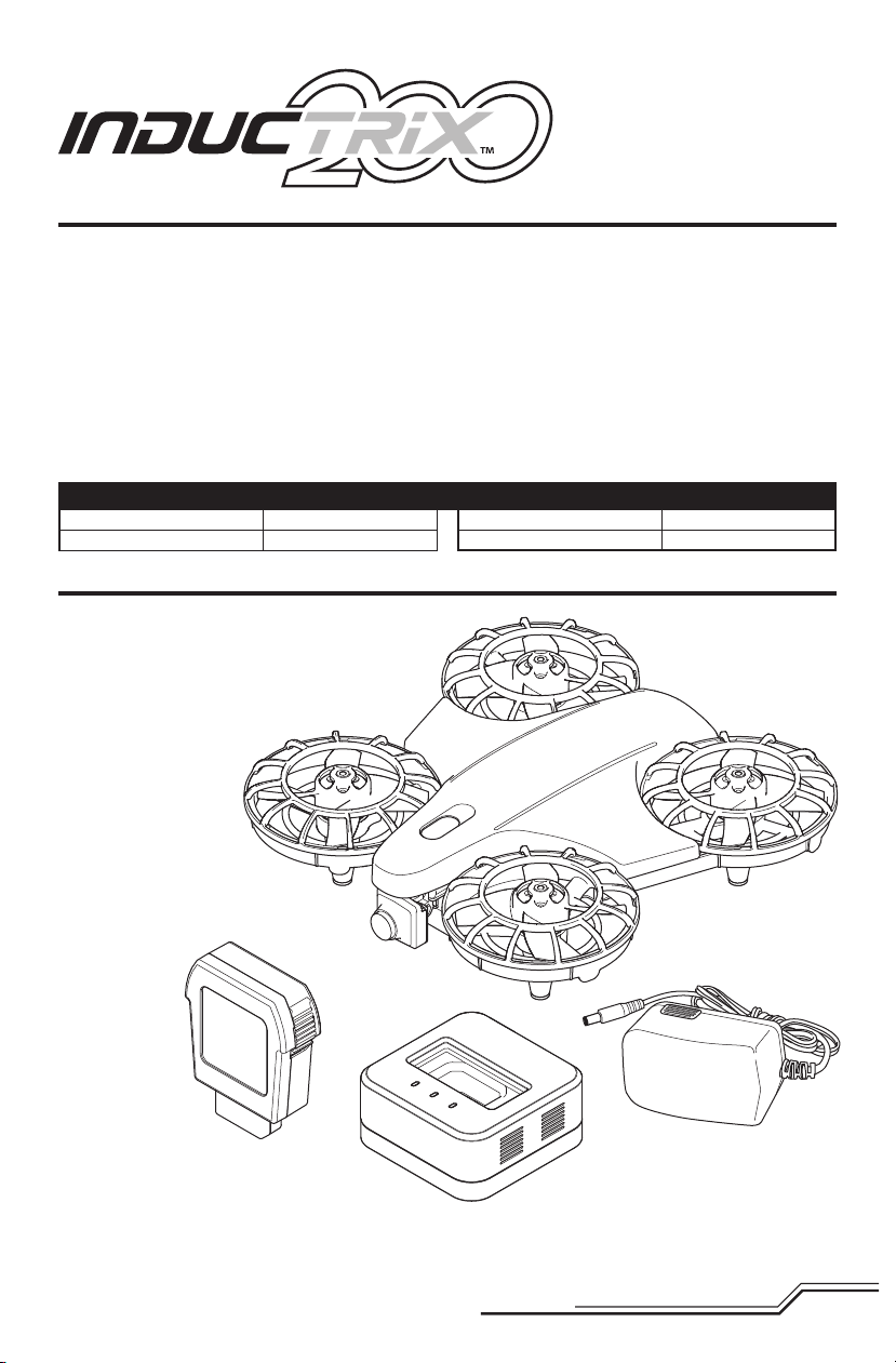
Table of Contents
Box Contents ...................................................................3
First Flight Preparation .....................................................4
Flying Checklist ...............................................................4
Charging Warnings...........................................................4
Battery Charging ..............................................................4
Transmitter Setup ............................................................5
Installing the Flight Battery ..............................................8
Powering On the Inductrix™ 200 Quadcopter ..................8
Transmitter and Receiver Binding .....................................8
SAFE® Technology ...........................................................9
Understanding the Primary Flight Controls .......................9
Flight Mode Selection ....................................................10
Flying the Inductrix™ Quadcopter .................................10
Specifications
Length
Height
6.1 in (155mm)
1.8 in (45mm)
Box Contents
• Blade® Inductrix™ 200 Quadcopter
• 25mW Micro Camera System
• 800mAh 3S 11.1V 15C LiPo
• 3S, 1.2 A LiPo Charger
• 13.5V, 1.3A Power Supply
Needed to Complete
• FPV Headset or
Ground Station Receiver
• Full Range
DSM2®/DSMX
Transmitter (DX6i and up)
®
Using the Micro Camera.................................................11
Post-Flight Inspection and Maintenance Checklist ..........11
Replacing the Propellers ................................................12
Drift Calibration..............................................................12
Troubleshooting Guide ...................................................13
Exploded View ...............................................................14
Parts Listings .................................................................14
Optional Parts ................................................................14
Limited Warranty ...........................................................15
Warranty and Service Contact Information .....................16
FCC Statement...............................................................16
IC Information ................................................................16
Compliance Information for the European Union .............16
Propeller Diameter
Flying Weight
2.1 in (55mm)
6.5 oz (185 g)
To register your product online,visit www.bladehelis.com
3
EN
First Flight Preparation
• Remove and inspect contents
• Begin charging the fl ight battery
• Program your computer transmitter
• Familiarize yourself with the controls
• Install the fl ight battery in the quadcopter
(once it has been fully charged)
• Bind your transmitter
• Find a suitable area for fl ying
Charging Warnings
Flying Checklist
❏ Always turn the transmitter on fi rst
❏ Plug the fl ight battery into the lead from the 3-in-1 ESC
❏ Allow the receiver and ESC to initialize and arm
❏ Fly the model
❏ Land the model
❏ Unplug the fl ight battery from the 3-in-1 ESC
❏ Always turn the transmitter off last
CAUTION: All instructions and warnings must
be followed exactly. Mishandling of Li-Po batteries can result in a fi re, personal injury and/or property
damage.
• NEVER LEAVE CHARGING BATTERIES UNATTENDED.
• NEVER CHARGE BATTERIES OVERNIGHT.
• By handling, charging or using the included Li-Po battery,
you assume all risks associated with lithium batteries.
• If at any time the battery begins to balloon or swell,
discontinue use immediately. If charging or discharging,
discontinue and disconnect. Continuing to use, charge
or discharge a battery that is ballooning or swelling can
result in fi re.
• Always store the battery at room temperature in a dry
area for best results.
• Always transport or temporarily store the battery in a
temperature range of 40–120º F (5–49° C).
• Do not store battery or model in a car or direct sunlight.
If stored in a hot car, the battery can be damaged or
even catch fi re.
Battery Charging
NOTICE: Charge only batteries that are cool to the touch
and are not damaged. Look at the battery to make
sure it is not damaged e.g., swollen, bent, broken or
punctured.
CAUTION: Only use chargers specifi cally
designed to charge the included Li-Po battery.
Failure to do so could result in fi re, causing injury or
property damage.
CAUTION: Never exceed the recommended
charge rate.
Charger LED Indications
GREEN, Fast Flash = Ready to Charge
RED Flash = Charging
RED AND GREEN Flash = Cell Balancing
GREEN Solid = Full Charge
BLUE Solid or Flashing = Error
CAUTION: Once charging is complete,
immediately remove the battery. Never leave
a battery connected to the charger.
• Always charge batteries away from fl ammable materials.
• Always inspect the battery before charging
• Always disconnect the battery after charging, and
let the charger cool between charges.
• Always constantly monitor the temperature of the
battery pack while charging.
• ONLY USE A CHARGER SPECIFICALLY DESIGNED TO
CHARGE LI-PO BATTERIES. Failure to charge the battery
with a compatible charger may cause a fi re resulting in
personal injury and/or property damage.
• Never discharge Li-Po cells to below 3V under load.
• Never cover warning labels with hook and loop strips.
• Never charge batteries outside recommended levels.
• Never charge damaged batteries.
• Never attempt to dismantle or alter the charger.
• Never allow minors to charge battery packs.
• Never charge batteries in extremely hot or cold places
(recommended between 40–120° F or
(5–49° C) or place in direct sunlight.
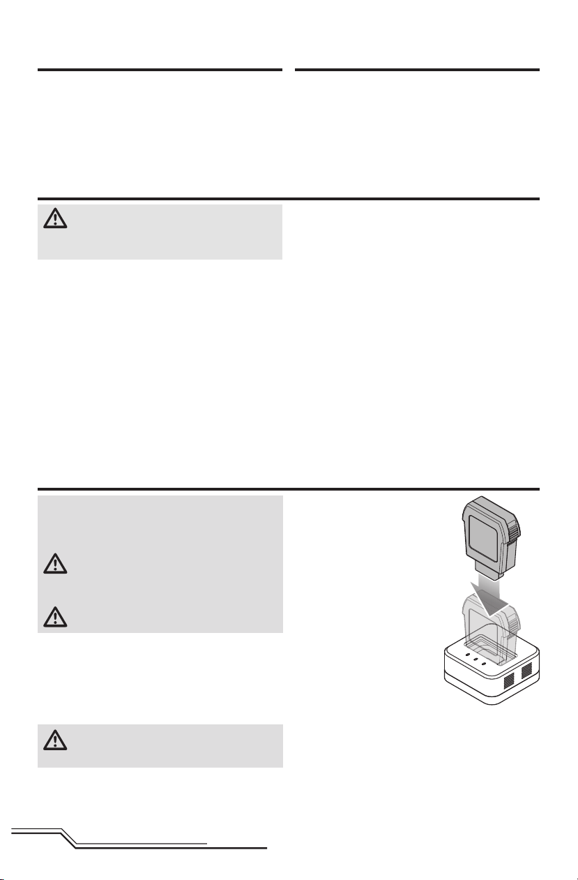
Use only the included power
supply with the included charger.
1. Connect the power supply to
the charger and to a suitable
outlet.
2. Insert the battery into the
charger.
3. Remove the battery from the
charger when the charging
cycle is complete.
4. Remove the power supply from
the AC outlet and charger.
Charger Blue LED Error Codes
One Flash = Initialization failed
Two Flashes = Input voltage error
Three Flashes = Battery error
Four Flashes = Charge current error
Five Flashes = Charge time protection
Solid = Hardware protection (Voltage > 4.3V )
EN
4
Transmitter Setup
Program your transmitter before attempting to bind or fl y
the quadcopter. Transmitter programming values are shown
below for the Spektrum DX6i, DX7s, DX6, DX7, DX8, DX9
and DX18.
The fi les for models using Spektrum™ transmitters with
AirWare™ software are also available for download online
at www.spektrumrc.com.
Your quadcopter is also compatible with Spektrum DXe
radios with software version 1.3 or higher. Use the directions
below to reverse channel 6, or use the appropriate programming cable and the PC or mobile app to program the DXe.
We recommend downloading the Blade
model setup available at www.spektrumrc.com.
®
Inductrix™ DXe
DXe
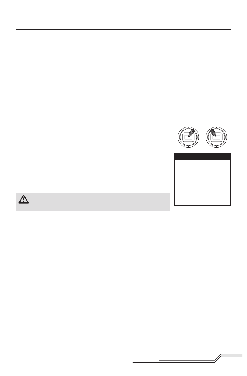
To use the DXe transmitter with the Blade Inductrix, channel 6 must be reversed.
To reverse channel 6:
1. While powering on the DXe, hold the left and right sticks in the top-inside corners
as shown.
2. Re-center the sticks after the transmitter beeps. The LED will fl ash slowly.
3. To select a channel to reverse, move the right stick to the left or right and allow it
to re-center. Move the stick to the right to select the next channel. Move the stick
to the left to select the previous channel. The LED will fl ash rapidly corresponding
to the channel selected, as shown in the table. Select channel 6.
4. To reverse the selected channel, move the right stick up or down. The LED will
change color to indicate the new channel direction.
The LED will fl ash Orange to indicate the channel is normal.
The LED will fl ash Red to indicate the channel is reversed.
5. To store the changes, power off the DXe.
CAUTION: During the subsequent power up, always verify the throttle
direction is correct and keep clear of the motor and rotor blades. Failure to do
so may result in injury or damage to the product.
If you are programming your DXe using the PC or mobile
app, make sure the "Transmitter Channels" value is set to
the default of 7. If for any reason this value is changed
to 9, the Inductrix will bind to the DXe, but will not respond
to control inputs.
If your DXe was included in another Blade Ready To Fly (RTF)
helicopter, the transmitter software will have to be updated
using the appropriate programming cable and either the
PC or mobile app available at www.spektrumrc.com.
Please note, the switch confi guration used for DXe transmitters included with the Blade 230 S RTF and Micro AH-64
Apache RTF varies from the standard DXe layout.
LED Flashes Channel
1 1-Throttle
2 2-Aileron
3 3-Elevator
4 4-Rudder
5 5-Flight Mode
6 6-Motor Stop
7 7-Flaps
8 8-Aux Channel
After reversing channel 6, bind the transmitter and
quadcopter normally.
Flight modes are controlled by the Flight Mode switch.
Motor Stop is controlled by the Bind/Panic/Trainer button.
Once bound, the LED in the quadcopter should glow
blue for fl ight mode 0 (Stability, low angle mode), green
for fl ight mode 1 (Stability, high angle mode) and red for
fl ight mode 2 (Agility mode ).
If the motors will not start when giving the correct start
command, channel 6 has not been reversed correctly. Use
the directions above to reverse channel 6.
5
EN
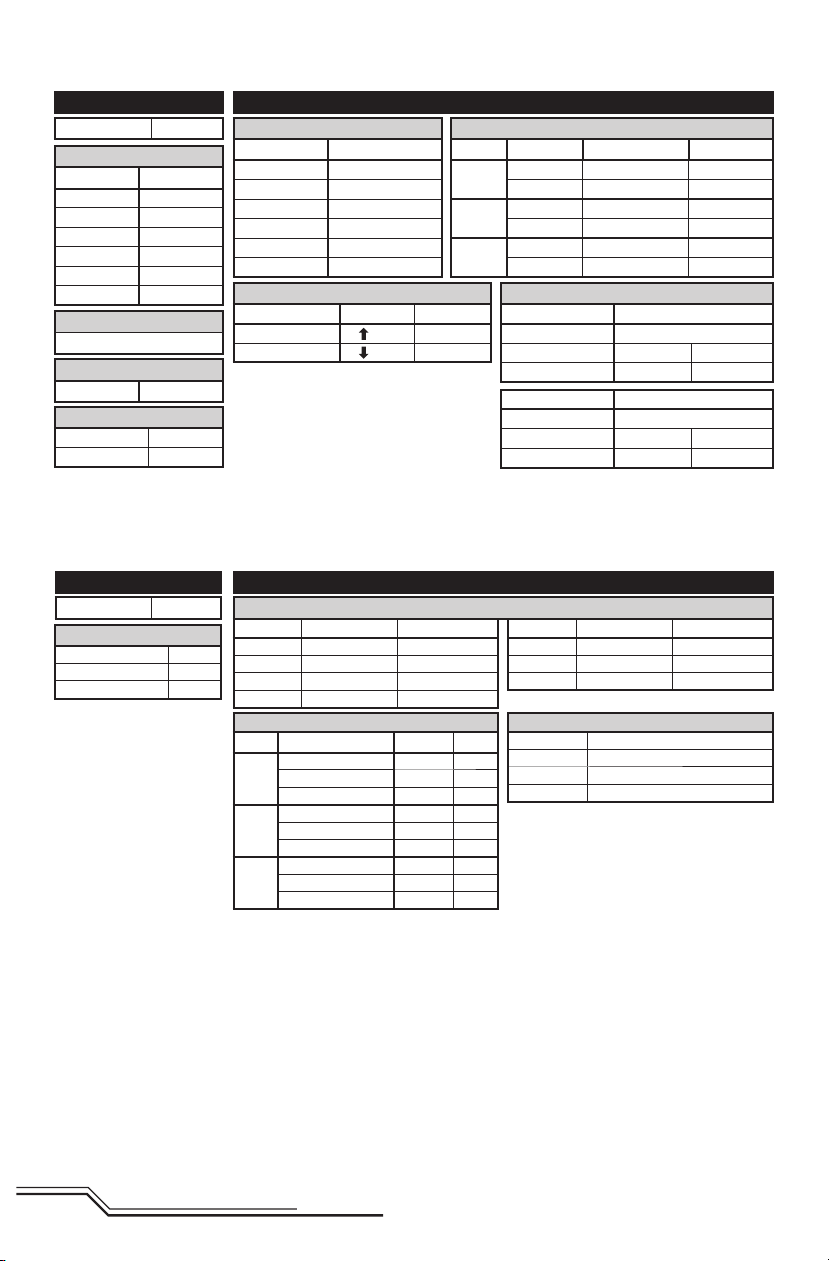
DX6i
ADJUST LISTSETUP LIST
Model Type Acro
REVERSE
Channel Direction
THRO N
AILE N
ELEV N
RUDD N
GEAR R
FLAP N
Modulation Type
AUTO DSMX-ENABLE
D/R COMBI
D/R SW AILE
Timer
Down Timer 5:00
Switch THR CUT
Motor Stop
Flap Switch
Pos 0 = Normal
Pos 1 = Motor Stop
TRAVEL ADJ
Channel Travel
THRO 100/100
AILE 100/100
ELEV 100/100
RUDD 100/100
GEAR 100/100
FLAP 100/100
FLAPS
FLAP ELEV
NORM 100 0
LAND 100 0
Flight Mode Operation
Gear Sw: Pos 0, Elev D/R Sw: 0 or 1 = Stability, Low-Angle Mode (quadcopter LED Blue)
Gear Sw: Pos 1, Elev D/R Sw: 0 = Stability, High-Angle Mode (quadcopter LED Green)
Gear Sw: Pos 1, Elev D/R Sw: 1 = Agility Mode (quadcopter LED Red)
D/R & Expo
Chan Sw Pos D/R Expo*
AILE
ELEV
RUDD
0 100 INH
1 75 INH
0 100 INH
1 75 INH
0 100 INH
1 75 INH
Mixing
MIX 1 ACT
GEAR > GEAR ACT
RATE D 0% U –100%
SW GEAR TRIM – INH
MIX 2 ACT
GEAR > GEAR ACT
RATE D 0% U +100%
SW ELE D/R TRIM – INH
DX7s
FUNCTION LISTSYSTEM SETUP
Model Type ACRO
SW Select
Trainer Aux 1
Flap Gear
All Others INH
Motor Stop
Bind / I Button
Pressed (~1 sec) = Motor Stop
* Use of "Expo" is not necessary for successful fl ight of the Inductrix 200. The pilot may adjust this setting to tailor the
sensitivity of the quadcopter around neutral if desired.
Servo Setup
Chan Travel Reverse
THR 100/100 Normal
AIL 100/100 Normal
ELE 100/100 Normal
RUD 100/100 Normal
D/R & Expo
Chan
Switch Pos (FLAP)
AILE
ELEV
RUDD
Flight Mode Operation
FLAP Sw: Pos 0 = Stability, Low-Angle Mode (quadcopter LED Blue)
0 100/100 0
1 100/100 0
2 75/75 0
0 100/100 0
1 100/100 0
2 75/75 0
0 100/100 0
1 100/100 0
2 75/75 0
Pos 1 = Stability, High-Angle Mode (quadcopter LED Green)
Pos 2 = Agility Mode (quadcopter LED Red)
D/R
Chan Travel Reverse
GER 100/100 Normal
AX1 100/100 Reverse
AX2 100/100 Normal
Timer
Mode Count Down
Expo*
Time 5:00 Tone
Start Throttle Out
Pos 25%
EN
6
 Loading...