

Blade Inductrix Instruction Manual [ml]
FPV RTF/BNF
®
Instruction Manual / Bedienungsanleitung / Manuel d’utilisation / Manuale di Istruzioni
EN
NOTICE
All instructions, warranties and other collateral documents are subject to change at the sole
discretion of Horizon Hobby, LLC. For up-to-date product literature, visit horizonhobby.com and
click on the support tab for this product.
MEANING OF SPECIAL LANGUAGE
The following terms are used throughout the product literature to indicate various levels of potential
harm when operating this product:
NOTICE: Procedures, which if not properly followed, create a possibility of physical property damage
AND a little or no possibility of injury.
CAUTION: Procedures, which if not properly followed, create the probability of physical property damage
AND a possibility of serious injury.
WARNING: Procedures, which if not properly followed, create the probability of property damage,
collateral damage, and serious injury OR create a high probability of superfi cial injury.
WARNING: Read the ENTIRE instruction manual to become familiar with the features of the product
before operating. Failure to operate the product correctly can result in damage to the product, personal
property and cause serious injury.
This is a sophisticated hobby product. It must be operated with caution and common sense and requires some
basic mechanical ability. Failure to operate this Product in a safe and responsible manner could result in injury
or damage to the product or other property. This product is not intended for use by children without direct
adult supervision. Do not attempt disassembly, use with incompatible components or augment product in any
way without the approval of Horizon Hobby, LLC. This manual contains instructions for safety, operation and
maintenance. It is essential to read and follow all the instructions and warnings in the manual, prior to assembly,
setup or use, in order to operate correctly and avoid damage or serious injury.
Age Recommendation: Not for children under 14 years. This is not a toy.
If you are operating this product in North America, you are required to have
an Amateur Radio (HAM) license. Visit www.arrl.org for more information.
Operating Safety Precautions
• As the user of this product, you are responsible for
operating it safely, not endangering yourself and others,
or damaging the product or the property of others.
• Operate your product in open spaces away from
people and property.
• Never operate your product with damaged electrical
components.
• Keep the transmitter powered on while model is
powered on.
• Let parts cool after use before touching, motors will
get hot in use.
• Remove batteries after use, as applicable.
General Product Safety Precautions
• Keep all batteries, chemicals, small parts and
anything electrical out of the reach of children.
Length
Height
3.26 in (83mm)
1.10 in (28mm)
To receive product updates, special offers and more, register your product at www.bladehelis.com.
• Avoid water exposure to this product. Keep parts dry.
• Keep moving parts clean.
Specifications
Propeller Diameter
Flying Weight
2.56 in (65mm)
.85 oz (24 g)
Charging Warnings
WARNING: Failure to comply with the
following warnings could result in product
malfunction, electrical issues, excessive heat,
FIRE, and ultimately injury and property damage.
• NEVER LEAVE CHARGING BATTERIES
UNATTENDED.
• NEVER CHARGE BATTERIES OVERNIGHT.
• Never charge damaged batteries. If the battery
begins to swell during charging or use, discontinue
immediately.
• Always use the included battery and charger.
Disconnect the battery after charging.
• Charge batteries away from fl ammable materials
in a well-ventelated area.
• Never charge, transport, or store batteries in hot,
cold, or very sunny places
(recommended between 40–120° F or 5–49° C).
Charge the Flight Battery
NOTICE: Inspect the battery to make sure it is not damaged e.g., swollen, bent, broken or
punctured. Charge only batteries that are cool to the touch and are not damaged.
Insert the charger into a USB port.
Connect the battery to the charger.
CHARGING (Solid Red LED)
USB Li-Po
Charger
DC Input:5.0V 350mA
DC Output:4.2V 300mA
SOLID RED LED
–Charging
LED OFF
–Charge
Complete
EFLC1008
MAX CHARGE (LED OFF )
Disconnect the fl ight battery from the charger immediately upon completion of charging.
CAUTION: Only use chargers specifi cally designed to charge the included Li-Po battery.
Failure to do so could result in fi re, causing injury or property damage.
CAUTION: Never exceed the recommended charge rate.
CAUTION: Once charging is complete, immediately remove the battery.
Never leave a battery connected to the charger.
Install the Transmitter Batteries (RTF)
Install 4 AA batteries into the transmitter, noting
polarity. Replace the transmitter batteries when the
power LED fl ashes and the transmitter beeps.
We recommend using only alkaline AA batteries
in the transmitter, however, it is possible to use
rechargeable NiMH batteries.
CAUTION: If using rechargeable batter-
ies, charge only rechargeable batteries.
Charging non-rechargeable batteries may cause
the batteries to burst, resulting in injury to
persons and/or damage to property.
Install the Flight Battery
1
Throttle down
CAUTION: Always disconnect the Li-Po battery from the aircraft
when not fl ying to avoid over-discharging the battery. Batteries
discharged to a voltage lower than the lowest approved voltage may
become damaged, resulting in loss of performance and potential fi re
when the batteries are charged.
2
Power ON
3
4
Transmitter and Receiver Binding
Your RTF transmitter comes prebound to the Inductrix. If you need to re-bind, follow the directions below.
MLP4DSM Binding Procedure (RTF)
1. Disconnect the fl ight battery from the quadcopter.
2. Center all trims on your transmitter.
3. Power off the transmitter and fully lower the throttle.
4. Connect the fl ight battery in the quadcopter. The LED on the 3-in-1 control unit fl ashes red during
initialization, then fl ashes blue when it is ready to bind.
5. When the blue light is fl ashing, push in and hold down the left stick while powering on the transmitter (you will hear a ‘click’ and a long tone).
6. Release the left stick. The transmitter will beep and the power LED will blink. The quadcopter is
bound when the blue LED on the 3-in-1 control unit turns solid.
7. Disconnect the fl ight battery and power the transmitter off.
®
BNF
Transmitter
If you are using a computer transmitter, in the channel input menu, set channel 6 (Aux1) to a momentary
switch such as the bind button (I). Set the model type to “Acro” or “Airplane” mode. Bind the quadcopter
to your transmitter following the directions below.
General Binding Procedure (BNF®)
1. Disconnect the fl ight battery from the quadcopter.
2. Set the model type in your transmitter settings to “Acro” mode.
3. Center all trims on your transmitter.
4. Power off the transmitter and fully lower the throttle.
5. Connect the fl ight battery in the quadcopter. The LED on the 3-in-1 control unit fl ashes red
during initialization, then fl ashes blue when it is ready to bind.
6. Put the transmitter into bind mode while powering on the transmitter.
7. Release the bind button/switch after 2–3 seconds. The quadcopter is bound when the blue LED
on the 3-in-1 control unit turns solid.
8. Disconnect the fl ight battery and power the transmitter off.
If you encounter problems, obey the binding instructions and refer to the troubleshooting guide for
other instructions. If needed, contact the appropriate Horizon Product Support offi ce. For a list of
compatible DSM
®
transmitters, please visit www.bindnfl y.com.
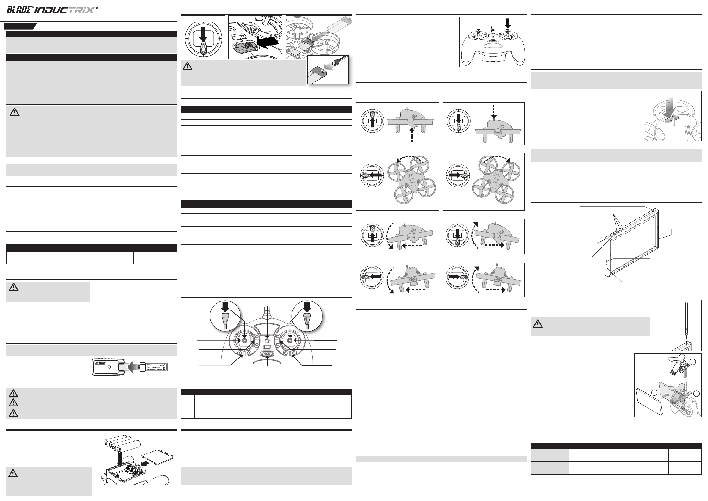
Transmitter Control (RTF)
Power LED indicator
Bind/
Flight Mode
Selection
F
E
D
On/Off Switch
Dual rate
selection
A
B
C
When pressed down, trim buttons make a sound that increases or decreases in pitch at each
pressing. The middle or neutral trim position is heard as a middle tone in the pitch range of the
sounds. The end of the control range is sounded by a series of beeps.
A B C D E F
Mode1Aileron (Left/Right)
Throttle (Up/Down)
Mode2Aileron (Left/Right)
Elevator (Up/Down)
Throttle
Trim
Elevator
Trim
Aileron
Trim
Aileron
Trim
Rudder
Trim
Rudder
Trim
Elevator
Trim
Throttle
Trim
Rudder (Left/Right)
Elevator (Up/Down)
Rudder (Left/Right)
Throttle (Up/Down)
Flight Mode Selection
Cycle between the fl ight modes by pressing and releasing the left stick of the MLP4DSM or by pressing and
releasing the momentary switch on your computer transmitter as programmed in the binding section above.
• S tability mode (blue LED): the bank angle is limited. When the sticks are released, the quadcop-
ter will return to level fl ight.
• A gility mode (red LED): the quadcopter has no bank angle limits and will not return to level fi ght if
the sticks are released. Use rates and expo to tune the performance according to your fl ying style.
NOTICE: Do not attempt to change fl ight modes while fl ying with the MLP4DSM transmitter.
Attempting to do so will cause the transmitter to register a faulty center position. Always land the
quadcopter and release the sticks before changing fl ight modes.
Rate Selection – RTF
The Inductrix® RTF quadcopter comes with the Blade
MLP4DSM transmitter.
• When powered on, this transmitter is automatically high rate.
• Change rates by pressing and releasing the right control stick.
• In low-rate mode, the quadcopter is limited to a lower bank
angle and will self-level when the control sticks are released.
This mode is typically preferred by pilots looking for smoother/
easier control response during fi rst time use.
• In high-rate mode, the quadcopter has a higer possible bank
angle and will self-level when the control sticks are released.
®
Dual rate selection
Understand the Primary Flight Controls
If you are not familiar with the controls of your Inductrix quadcopter, take a few minutes to familiarize
yourself with them before attempting your fi rst fl ight.
Throttle
Throttle up
Left Side View Left Side View
Climb
Throttle down
Descend
Rudder
Rudder left
Nose Yaws Left
Rudder right
Nose Yaws Right
Elevator
Left Side View Left Side View
ForwardElevator down
Elevator up
Backward
Aileron
Aileron left
Left
Rear View
Aileron right
Rear View
Right
Fly the Quadcopter
The LEDs on the Inductrix indicate the front and back of the quadcopter. The white LEDs indicate the front.
The red LEDs indicate the back.
Takeo
Increase the throttle until the model is approximately 2 ft. (600mm) off the ground in a low-level hover and
concentrate on balancing the throttle stick’s position so that the quadcopter holds a steady hover altitude. In
some cases, you may need to make a few short “hops” to an altitude of just a few inches until you become
familiar with the control inputs and trim settings required to maintain a steady hover and altitude.
Hovering
The Inductrix quadcopter requires minor throttle adjustments to maintain its altitude in hover. Remember to keep these throttle adjustments as minimal as possible. Large adjustments could result in a
loss of control or a possible crash.
While attempting to establish a low-level hover, check to see if any trim adjustments are required to
help keep the quadcopter from constantly drifting in various directions. If you fi nd that it constantly drifts
without any directional control input, land the model before making any adjustments to the trim settings.
• If the nose of the quadcopter rotates to the left or right, adjust the rudder trim.
• If the quadcopter continually drifts forward or backward, adjust the elevator trim.
• If the quadcopter continually drifts to the left or right, adjust the aileron trim.
Continue making minor trim adjustments until the machine hovers at a low altitude with very little
drifting and directional control input. If this is your fi rst multicopter or helicopter, seek the help of an
experienced pilot to trim the model for you before making your fi rst fl ight.
With your quadcopter properly trimmed and maintaining a stable low-level hover, practice using the
rudder, elevator and aileron controls to familiarize yourself with the machine’s responses to control
inputs. Remember to keep the control inputs as minimal as possible.
Average fl ight times are approximately 4 minutes.
NOTICE: Crash damage is not covered under warranty.
To prevent excessive wear to the motors, always allow the motors to cool between fl ights.
1
Low Voltage Cuto (LVC)
Once the battery reaches 3V under load, the ESC will continuously lower power supplied to the motor
until complete shutdown occurs. This helps prevent over-discharge of the Li-Po battery. Land immediately once the ESC activates LVC. Continuing to fl y after LVC can damage the battery, cause a crash
or both. Crash damage and batteries damaged due to over-discharge are not covered under warranty.
Repeatedly fl ying the aircraft until LVC activates will damage the fl ight battery.
Disconnect and remove the Li-Po battery from the aircraft after use to prevent trickle discharge.
During storage, make sure the battery charge does not fall below 3V per cell.
FPV Camera and Video Transmitter
NOTICE: Consult local laws and ordinances before operating FPV (fi rst person view) equipment.
In some areas, FPV operation may be limited or prohibited. You are responsible for operating this
product in a legal and responsible manner.
1. Power on your radio transmitter, then power on the aircraft.
2. Power on the video receiver to make sure the channel is clear.
3. Select the desired video transmitter channel by pressing the
button on the quadcopter as shown to scroll through the
available bands (Fat Shark/IRC or Race) and channels (1-8).
Fatshark channel 1 is indicated by a red internal LED on the
quadcopter. Keep pressing and releasing the button to scroll
through the remaining channels.
4. Perform a range test before fl ying.
If you experience static in the video feed, select a different channel.
NOTICE: The 25mW micro video transmitter range on your quadcopter is less than your fl ight
control transmitter range. Ensure you have adequate video camera range for fi lming.
Tip: If you are fl ying with an FPV headset and are prone to motion sickness, sit in a chair. If you start to
suffer from motion sickness while fl ying, lower your chin against your chest.
Fly in open areas, away from people, trees, cars, and buildings. The range of the system can be
impacted by any obstructions blocking your signal. It is normal to see break up in the video going
behind trees and other obstacles.
Video Monitor (RTF)
5.8GHz Antenna connector
Menu Button:
Use the + and – buttons to modify:
Brightness
Contrast
Color
Channel Selection Button
Single push to change channel
Frequency Band Button
Single push to change band
1. Before using the Spektrum
Connect the micro USB connector to a 5V USB power source. The charge indicator LED will glow
red while charging and green when the monitor is fully charged.
2. Attach the included antenna to the antenna connector located on
the top of the monitor.
CAUTION: Do not power the monitor on without the antenna
attached. Doing so will damage the video transmitter and
receiver amplifi ers. Amplifi er damage is not covered by warranty.
3. Attach the fpv monitor holder to the MLP4DSM
transmitter.
a. Slide the holder down over the antenna.
b. Tighten the clamp screw. Do not overtighten.
c. Open the clamp jaws and place the monitor in the
jaws. The angle of the monitor can be adjusted by
loosening the angle adjustment knob, rotating the
clamp up or down and tightening the adjustment knob.
4. Turn on the monitor and look for a clear channel. Clear channels will have a consistent static background.
Channels with interference will display horizontal static lines. Select one of the clear channels. The video
transmitter included with the Inductrix FPV quadcopter transmits only on the Fat Shark/IRC and RaceBand
bands, channels 1-8.
BAND CH 1 CH 2 CH 3 CH 4 CH 5 CH 6 CH 7 CH 8
Fat Shark/IRC 5740 5760 5780 5800 5820 5840 5860 5880
RaceBand 5658 5695 5732 5769 5806 5843 5880 5917
Band E 5705 5685 5665 5645 5885 5905 5925 5945
Band A 5865 5845 5825 5805 5785 5765 5745 5725
5. Once you have chosen a clear channel on the monitor, select the same channel on the video transmitter.
Mode (16:9, 4:3)
Language
AV In
Reset
ON/Off Switch
Charge Status LED
Red = charging
Green = charged
5V Micro USB Charge Port
®
4.3 inch Video Monitor make sure the monitor is charged thoroughly.
c
a
b
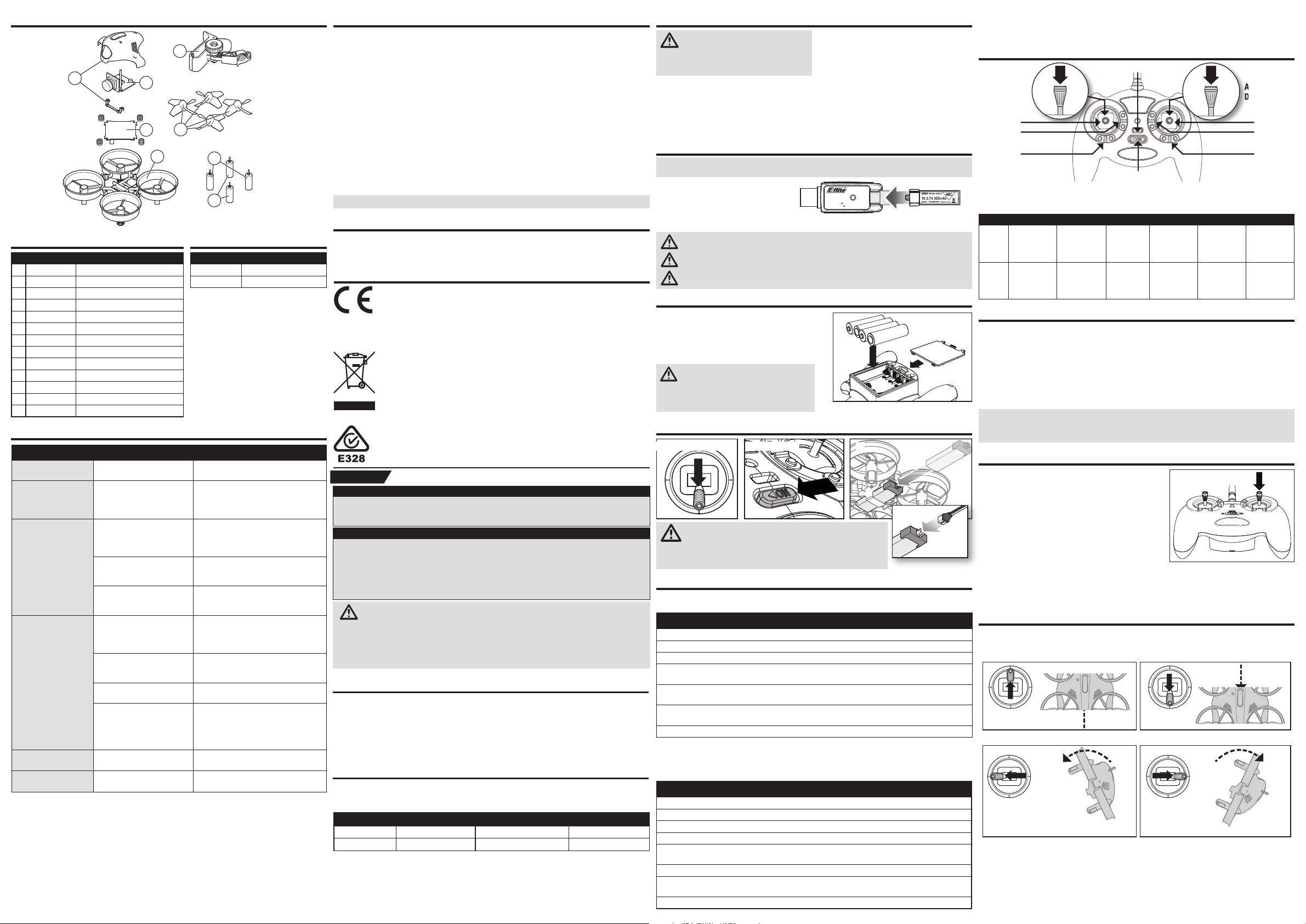
Exploded View
Auswahl
Dual Rate
4
Parts List
Part # Description
BLH8500 Inductrix FPV RTF
BLH8580 Inductrix FPV BNF
1 BLH8501 Main Control Board
2 BLH8502 Clockwise Motor, Speed
3 BLH8503 Counter Clockwise Motor, Speed
4 BLH8504 Canopy: Inductrix FPV
5 BLH8505 FPV Camera 25mW w/ Raceband
6 BLH8506 Prop Set (4), Yellow
7 BLH8706 Main Frame
8 BLH2208 Smart Phone Holder: mLP TX
EFLC1008 1S USB Li-Po Charger, 300mA
EFLB2001S45 1S, 200mAh LiPo
SPMVM430 4.3 inch video monitor
Troubleshooting Guide
Problem Possible Cause Solution
Will not respond to
throttle
Does not function
and smells burnt after
connecting the fl ight
battery
LED on receiver fl ashes
rapidly and quadcopter
will not respond to transmitter (during binding)
LED on the receiver
fl ashes rapidly and the
quadcopter will not respond to the transmitter
(after binding)
Crashes immediately upon
lift-off or doesn’t lift off
Static in FPV feed
Throttle too high and/or throttle
trim is too high
Flight battery connected with the
wrong polarity
Transmitter too near aircraft
during binding process
Bind switch or button was not
held while transmitter was
powered on
Aircraft or transmitter is too close
to large metal object, wireless
source or another transmitter
Less than a 5-second wait
between fi rst powering on the
transmitter and connecting the
fl ight battery to the quadcopter
The quadcopter is bound to
a different model memory
(ModelMatch
Flight battery or transmitter battery charge is too low
Aircraft or transmitter is too
close to
large metal object, wireless
source or
another transmitter
Propellers in wrong locations Make necessary adjustments
Interference on chosen channel
™
transmitters only)
FCC Information
This equipment has been tested and found to comply with the limits for Part 15 of the FCC rules.
8
5
1
6
7
2
3
These limits are designed to provide reasonable protection against harmful interference in a residential installation. This equipment generates uses and can radiate radio frequency energy and, if
not installed and used in accordance with the instructions, may cause harmful interference to radio
communications.
However, there is no guarantee that interference will not occur in a particular installation. If this equipment does cause harmful interference to radio or television reception, which can be determined by
turning the equipment off and on, the user is encouraged to try to correct the interference by one or
more of the following measures:
• Reorient or relocate the receiving antenna.
• Increase the separation between the equipment and receiver.
• Connect the equipment to an outlet on a circuit different from that to which the receiver is
connected.
This device complies with part 15 of the FCC rules. Operation is subject to the following two
conditions: (1) This device may not cause harmful interference, and (2) this device must accept any
interference received, including interference that may cause undesired operation.
NOTICE: Modifi cations to this product will void the user’s authority to operate this equipment.
IC Information
Optional Parts List
Part # Description
EFLB1501S45 1S, 150mAh LiPo
SPMVM430HA Headset conversion
This device complies with Industry Canada license-exempt RSS standard(s). Operation is subject to
the following two conditions: (1) this device may not cause interference, and (2) this device must accept any interference, including interference that may cause undesired operation of the device.
Compliance Information for the European Union
EU Compliance Statement:
Horizon Hobby, LLC hereby declares that this product is in compliance with the essential
requirements and other relevant provisions of the R&TTE, RED, EMC and LVD Directives.
A copy of the EU Declaration of Conformity is available online at:
http://www.horizonhobby.com/content/support-render-compliance.
Instructions for disposal of WEEE by users in the European Union
This product must not be disposed of with other waste. Instead, it is the user’s
responsibility to dispose of their waste equipment by handing it over to a designated
collections point for the recycling of waste electrical and electronic equipment. The
separate collection and recycling of your waste equipment at the time of disposal will
help to conserve natural resources and make sure that it is recycled in a manner that
protects human health and the environment. For more information about where you
can drop off your waste equipment for recycling, please contact your local city offi ce,
your household waste disposal service or where you purchased the product.
Warnungen zum Laden
WARNUNG: Alle Anweisungen und
Warnhinweise müssen genau befolgt
werden. Falsche Handhabung von Li-PoAkkus kann zu Brand, Personen- und/oder
Sachwertschäden führen.
• ADEN SIE NIEMALS AKKUS UNBEAUFSICHTIGT.
• LADEN SIE NIEMALS AKKUS ÜBER NACHT.
• Laden Sie njemals beschädigte Akkus Sollte der
Akku zu einem beliebigen Zeitpunkt beginnen, sich
aufzublähen oder anzuschwellen, stoppen Sie die
Verwendung unverzüglich.
• Verwenden Sie immer das Ladegerät und den Akku
aus dem Lieferumfang. Trennen Sie nach dem Laden
den Akku.
• Laden Sie die Akkus immer weit entfernt von
brennbaren in gut belüfteten Bereichen.
• Laden, transportieren oder lagern Sie niemals
Akkus in heißen, kalten oder Plätzen mit starker
Sonneneinstrahlung. (Empfohlener Temperaturbereich
40 - 120°)
Laden des Flugakkus
HINWEIS: Laden Sie Akkus nur, wenn sie auf Umgebungstemperatur abgekühlt sind. Schauen Sie sich
den Akku an und stellen Sie sicher, dass dieser nicht beschädigt oder aufgequollen ist.
Stecken Sie den Lader in den USB Port.
Schließen Sie den Akku an das Ladegerät.
Laden (LED rot )
Fertig geladen (LED aus)
Entnehmen Sie den Akku immer aus dem Lader, sobald der Ladevorgang beendet ist.
ACHTUNG: Verwenden Sie nur Ladegeräte, die für LIPO Akkus vorgesehen sind.
Nichtbeachtung kann zu Feuer, Beschädigungen oder Verletzungen führen.
ACHTUNG: Überschreiten Sie niemals die vorgesehene Ladezeit.
ACHTUNG: Entnehmen Sie den Akku aus dem Lader, sobald dieser fertig geladen ist.
Belassen Sie den Akku niemals im Lader.
USB Li-Po
Charger
DC Input:5.0V 350mA
DC Output:4.2V 300mA
SOLID RED LED
–Charging
LED OFF
–Charge
Complete
EFLC1008
Einsetzen der Senderbatterien (RTF)
Setzen Sie unter Beobachtung der Polarität die
Senderbatterien ein. Ersetzen Sie die Batterien
wenn die LED blinkt und der Sender piept.
Wir empfehlen AA Alkaline Batterien in dem Sender
zu verwenden. Sie können auch wiederaufl adbare
NiMH Akkus verwenden.
ACHTUNG: Wenn Sie wiederaufl adbare
Akkus verwenden, laden Sie nur diese. Das
Laden von nicht wiederaufl adbaren Batterien kann die
Batterien zur Explosion bringen, was Körperverletzung
und Sachbeschädigung zur Folge haben kann.
Einsetzen des Flugakkus
1 Gas nach unten 2 Einschalten
3
Wenn Probleme auftreten beachten Sie bitte die Bindeanweisungen und schauen in die Hilfestellung
zur Problemlösung. Kontaktieren Sie falls notwendig den technischen Service von Horizon Hobby. Eine
Liste der kompatiblen DSM Sender sehen Sie unter www.bindnfl y.com.
Sendersteuerung (RTF)
Ein/Aus-LED
Auswahl des
Bindungs-/
Flugmodus
F
E
D
Wenn die Trimmtasten gedrückt werden, geben sie einen Signalton von sich, der bei jedem erneuten
Drücken höher oder tiefer wird. Die mittlere oder neutrale Trimmstellung erklingt in der mittleren
Tonhöhe. An den äußeren Enden des Steuerbereichs erklingt eine Tonfolge.
H A B C D E F
Querruder
Modus
1
Modus
2
(links/rechts)
Gas (auf/ab)
Querruder
(links/rechts)
Höhenruder
(auf/ab)
Gas trimm
Höhenrudertrimm
EIN/AUS-Schalter
Querrudertrimm
Querrudertrimm
Seitenrudertrimm
Seitenrudertrimm
Höhenrudertrimm
Gas trimm
Auswahl
Dual Rate
A
B
C
Seitenruder
(links/rechts)
Höhenruder
(auf/ab)
Seitenruder
(links/rechts)
Gas (auf/ab)
Auswahl des Flugmodus
Zwischen den Flugmodi umschalten indem der linke Steuerknüppel auf MLP4DSM betätigt und freigeben
wird oder durch Betätigen und Freigeben des Tasters auf Ihrem Computersender, wie im Abschnitt zur
Bindung beschrieben.
• Stabilitätsmodus (blaue LED): die Schräglage ist begrenzt. Werden die Steuerknüppel losgelas-
sen, wird der Quadcopter in den Horizontalfl ug zurückkehren.
• Agilitätsmodus (rote LED): der Quadcopter verfügt über keine Begrenzung der Schräglage und
wird nicht in den Horizontalfl ug zurückkehren, wenn die Steuerknüppel losgelassen werden. Verwenden Sie Geschwindigkeiten und Exponential zum Einstellen der Leistung entsprechend Ihres Flugstils.
HINWEIS: Versuchen Sie nicht die Flugmodi während des Fliegens mit dem MLP4DSM-Sender zu ändern.
Der Versuch wird dazu führen, dass der Sender eine fehlerhafte Mittelposition erkennt. Landen Sie immer
den Quadcopter und lassen Sie die Steuerknüppel los, ehe Sie die Flugmodi ändern.
Dual Rate (RTF)
Reset controls with the throttle stick
and throttle trim at the lowest setting
Replace the 3-in-1 board. Connect the fl ight
battery noting proper polarity
Power off the transmitter. Move the transmitter a larger distance from the aircraft. Disconnect and reconnect the fl ight battery to
the aircraft. Follow the binding instructions
Power off transmitter and repeat bind
process
Move aircraft and transmitter to another
location and attempt binding again
Leave the transmitter powered on. Disconnect and reconnect the fl ight battery to the
quadcopter
Select the correct model memory on the
transmitter. Disconnect and reconnect the
fl ight battery to the quadcopter
Replace or recharge batteries
Move aircraft and transmitter to another
location and attempt connecting again
Change the video transmitter and receiver
channel
DE
HINWEIS
Alle Anweisungen, Garantien und anderen zugehörigen Dokumente können im eigenen Ermessen
von Horizon Hobby, LLC jederzeit geändert werden. Die aktuelle Produktliteratur fi nden Sie auf
horizonhobby.com unter der Registerkarte „Support“ für das betreffende Produkt.
BEDEUTUNG DER SIGNALWÖRTER
Die folgenden Begriffe werden in der gesamten Produktliteratur verwendet, um auf unterschiedlich hohe
Gefahrenrisiken beim Betrieb dieses Produkts hinzuweisen:
HINWEIS: Wenn diese Anweisungen nicht korrekt befolgt werden, können sich möglicherweise
Sachschäden UND geringe Gefahr von Verletzungen ergeben.
ACHTUNG: Wenn diese Anwesiungen nicht korrekt befolgt werden, ergeben sich wahrscheinlich
Sachschäden UND die Gefahr von schweren Verletzungen.
ACHTUNG: Lesen Sie die GESAMTE Bedienungsanleitung, um sich vor dem Betrieb mit den
Produktfunktionen vertraut zu machen. Wird das Produkt nicht korrekt betrieben, kann dies zu
Schäden am Produkt oder persönlichem Eigentum führen oder schwere Verletzungen verursachen.
Dies ist ein hochentwickeltes Hobby-Produkt. Es muss mit Vorsicht und gesundem
Menschenverstand betrieben werden und benötigt gewisse mechanische Grundfähigkeiten.
Versuchen Sie nicht ohne Genehmigung durch Horizon Hobby, LLC das Produkt zu zerlegen, es
mit inkompatiblen Komponenten zu verwenden oder auf jegliche Weise zu erweitern.
Nicht geeignet für Kinder unter 14 Jahren. Dies ist kein Spielzeug.
Sicherheitsvorkehrungen und Warnhinweise
• Als Nutzer dieses Produktes sind Sie allein für den
sicheren Betrieb ohne Gefährdung des Produktes,
ihrer selbst und dritter oder deren Eigentum
verantwortlich.
• Betreiben Sie ihr Produkt auf weiten, offenen Flächen
weg von Menschen und anderem Eigentum
• Betreiben Sie das Produkt niemals mit beschädigten
elektrischen Komponenten
Allgemeine Sicherheitshinweise zum Produkt
• Halten Sie alle Akkus, Batterien, Chemikalien und
Kleinteile und andere elektrische Komponenten aus
der Reichweite von Kindern.
Spezifikationen
Länge
Höhe
Bitte registrieren Sie ihr Produkt unter www.bladehelis.com um Updates, spezielle Angebote und
weitere Informationen zu erhalten.
83mm
28mm
• Lassen Sie den Sender eingeschaltet wenn das
Modell eingeschaltet ist
• Lassen Sie die Teile abkühlen bevor Sie sie anfassen.
Die Motoren werden während des Betriebes heiß
• Allgemeine Sicherheitshinweise zum Produkt
• Halten Sie alle Batterien, Akkus, Chemikalien Kleinteile
und Elektronikkomponenten aus der Reichweite von
Kindern
• Vermeiden Sie mit diesem Produkt Wasserkontakt.
Halten Sie die Teile trocken.
• Halten Sie die beweglichen Teile sauber.
Rotordurchmesser
Fluggewicht
65mm
24 g
4
ACHTUNG: Trennen Sie den Li-Po-Akku immer vom Empfänger
des Flugzeugs wenn Sie nicht fl iegen um eine Tiefentladung zu
vermeiden. Akkus die unter die zulässige Mindestspannung entladen werden, können dadurch beschädigt werden, was sich in Leistungsverlust und
potentieller Brandgefahr bei dem Laden bemerkbar machen kann.
Binden von Sender und Empfänger
Ihr RTF Sender ist bereits an das Modell gebunden. Sollten Sie neu binden wollen folgen Sie bitte den
untenstehenden Anweisungen.
MLP4DSM Bindeprozess
1. Trennen Sie den Flugakku vom Quadcopter.
2. Zentrieren Sie alle Trimmungen auf dem Sender.
3. Schalten Sie den Sender aus und reduzieren das Gas vollständig.
4. Installieren Sie den Akku im Quadcopter. Die LED auf der 3in1 Platine blinkt rot bei der Initialisierung
und dann blau, um Bindebereitschaft anzuzeigen.
5. Drücken Sie wenn die blaue LED blinkt den linken Steuerhebel ein während Sie den Sender ein-
schalten (Sie hören dabei ein Klick und einen langen Ton).
6. Lassen Sie den Stick los. Der Sender piept und die Power LED blinkt. Der Quad-Copter ist gebunden
wenn die LED auf der 3-in-1 Einheit blau leuchtet (nicht blinkt).
7. Trennen Sie den Flugakku und schalten den Sender aus.
BNF-Sender
Wenn Sie einen Computersender verwenden, stellen Sie im Kanaleingabemenü den Kanal6 (Aux1) auf
einen Taster, wie den Bindungsschalter (I). Stellen Sie den Modelltyp auf „Acro“ oder „Flugzeug“-Modus.
Binden Sie den Quadcopter an Ihren Sender unter Beachtung der nachfolgenden Anweisungen.
Der Bindevorgang
1. Trennen Sie den Flugakku von ihrem Quadcopter.
2. Wählen Sie im Sender den Modelltyp Acro.
3. Zentrieren Sie im Sender alle Trimmungen.
4. Schalten Sie den Sender aus und reduzieren das Gas vollständig.
5. Installieren Sie den Akku im Quadcopter. Die LED auf der 3in1 Platine blinkt rot bei der Initialisierung
und dann blau, um Bindebereitschaft anzuzeigen.
6. Bringen Sie den Sender in den Bindemode während Sie ihn einschalten.
7. Lassen Sie den Bindeschalter nach 2 -3 Sekunden los. Der Quad-Copter ist gebunden wenn die blaue
LED auf der 3-in-1 Einheit leuchtet.
8. Trennen Sie den Flugakku und schalten den Sender aus.
2
Der Glimpse RTF Quadcopter wird mit dem
Blade MLP4DSM Sender geliefert.
• Wenn Sie den Sender einschalten, befi ndet sich im Dual
Rate in Max.
• Die Dual Rate Einstellung ändern Sie durch drücken des
rechten Knüppels.
• Im Low Rate Mode mit den kleinen Ruderausschlägen
ist der Copter in der Schräglage limitiert und richtet sich
selber aus wenn die Steuerhebel los gelassen werden.
Dieser Mode ist für Piloten geeignet die für die ersten
Flüge gutmütige Reaktionen und einfache Kontrolle erwarten.
• Im High Rate Mode ist die mögliche Schräglage größer, der Copter richtet sich aber noch selber auf
wenn die Steuerhebel losgelassen werden.
Dual Rate Auswahl
Erklärung der Flugkontrollen
Bitte nehmen Sie sich vor dem Erstfl ug des Inductrix Quadcopter Zeit um sich mit den Kontrollen
vertraut zu machen.
Gasgeber
Gasgeber
nach oben
Seitenruder
Seitenruder
nach links
Seitenansicht Seitenansicht
Aufsteigen
Nase dreht nach links
Gasgeber
nach unten
Seitenruder
nach rechts
Sinken
Nase dreht nach rechts
 Loading...