

Blade G8264 Installation Manual

RackSwitch™ G8264
Inst allation Guide
Part Number: BPP-00039-00 rev 2, January 201 1
2051 Mission College Blvd.
Santa Clara, CA 95054
www.bladenetwork.net

RackSwitch G8264 Installation
Copyright © 2011 BLADE Network T echnologies, an IBM company , 2051 Mission College Blvd.,
Santa Clara, California, 95054, USA. All rights reserved. Part Number: BPP-00039-00 rev 2.
This document is protected by copyright and distributed under licenses restricting it s use, copying,
distribution, and decompilation. No part of this document may be reproduced in any form by any
means without prior written authorization of BLADE Network T echnologies. Documentation is
provided “as is” without warranty of any kind, either express or implied, including any kind of
implied or express warranty of non-infringement or the implied warranties of merchantability or
fitness for a particular purpose.
U.S. Government End Users: This document is provided with a “commercial item” as d efined by F AR
2.101 (Oct. 1995) and contains “commercial technical data” and “commercial software
documentation” as those terms are used in F AR 12.211-12.212 (Oct. 1995). Government End Users
are authorized to use this documentation only in accordance with those rights and restrictions set forth
herein, consistent with F AR 12.211- 12.212 (Oct. 1995), DFARS 22 7.7202 (JUN 1995) and DF ARS
252.227-7015 (Nov . 1995).
BLADE Network T echnologies reserves the right to change any products described herein at any
time, and without notice. BLADE Network T echnologies assumes no responsibility or liability
arising from the use of products described herein, except as expressly agreed to in writing by BLADE
Network T echnologies. The use and purchase of this product does not convey a license under any
patent rights, trademark rights, or any other intellectual property rights of BLADE Network
Technologies.
BLADE Network T echnologies, the BLADE logo, BLADEHarmony , BNT , NMotion, RackSwitch,
Rackonomics, RackSwitch Solution Partner, ServerMobility , SmartConnect and VMready are
trademarks of BLADE Network T echnologies. All other names or marks are property of their
respective owners.
Originated in the USA.
2 BPP-00039-00 rev 2, January 2011

Contents
Preface 5
RackSwitch G8264 Installation
Who Should Use This Book
Related Documentation
How to Get Help
6
5
5
Chapter 1: RackSwitch G8264 Description and Specifications
RackSwitch G8264 Features
Switch Components
Hardware Options
Switch Unit
Switch Ports
Switch LEDs
9
9
9
12
15
Technical Specifications
Physical Characteristics
Environmental Specifications
Power Specifications
Ordering Information
20
Chapter 2: Installing the RackSwitch G8264
Required Tools
Package Contents
23
23
Environmental Requirements
Preventing Electric Shock
Preventing Electrostatic Discharge
Installing the RackSwitch G8264 in a Standard Equipment Rack
Installing the RackSwitch G8264 in a 4-Post Rack
Installing the RackSwitch G8264 in an iDataPlex Rack
Installing the RackSwitch G8264 in a System X Rack
Initializing the RackSwitch G8264
Default Configuration
Configuring an IP Interface
Using the Boot Management Menu
Installing SFP/SFP+/QSFP+ Transceivers
SFP Copper Transceiver
SFP Optical Transceiver
SFP+ Optical Transceiver
7
18
18
18
19
23
24
24
25
26
29
34
37
42
43
43
45
46
46
47
48
7
BPP-00039-00 rev 2, January 2011 Contents
3

RackSwitch G8264 Installation
QSFP+ Optical Transceiver 49
Installing or Replacing a Power Supply Module
Removing an AC Power Supply Module
Installing an AC Power Supply Module
Installing or Replacing a Fan Module
Removing a Fan Module
Installing a Fan Module
Troubleshooting
System LEDs Do Not Light
Port link LED Does Not Light
Temperature Sensor Warning
Switch Does Not Initialize (Boot)
50
50
51
52
52
52
54
54
54
54
55
Appendix A: Safety and Compliance Statements
Safety Messages
Compliance Statements
57
62
57
Contents BPP-00039-00 rev 2, January 2011
4

Preface
This Installation Guide provides information and instructions for installing a Blade Network
Technologies RackSwitch G8264. For information about configuration and management of the
switch, refer to your Command Reference and the product release notes.
Who Should Use This Book
This Installation Guide is intended for network installers and system administrators engaged
in configuring and maintaining a network. It assumes that you are familiar with your
RackSwitch G8264, your Web browser, Ethernet concepts, IP addressing, the IEEE 802.1D
Spanning Tree Protocol, and SNMP configuration parameters.
Related Documentation
For documentation about configuring your switch, see the RackSwitch G8264 Application Guide
and Command Reference.
For details about the switch information, statistics, and configuration parameters, see the
RackSwitch G8264 Command Reference.
BPP-00039-00 rev 2, January 201 1 5

RackSwitch G8264 Installation
How to Get Help
If you need help, service, or technical assistance, call Blade Network Technologies Technical
Support:
US toll free calls: 1-800-414-5268
International calls: 1-408-834-7871
You also can visit our web site at the following address:
http://www.bladenetwork.net
Click the Support tab.
The warranty card received with your product provides details for contacting a customer
support representative. If you are unable to locate this information, please contact your reseller.
Before you call, prepare the following information:
Serial number of the switch unit
Software release version number
Brief description of the problem and the steps you have already taken
Technical support dump information (# show tech-support)
Note – In case of any suspected hardware related defect, immediately call the BLADE
support line to get the issue resolved. There are no field serviceable parts inside the enclosure and
tampering with internal compo nents in an attempt to diagnose hardware or fix defects will void the
warranty and the product will be repaired at the customer’s expense.
6 BPP-00039-00 rev 2, January 2011

CHAPTER 1
RackSwitch G8264
Description and Specifications
The RackSwitch G8264 is a rackable aggregation switch with unmatched line-rate Layer 2/3
performance. The G8264 uses a wire-speed, non-blocking switching fabric that provides
simultaneous wire-speed transport of multiple packets at low latency on all ports.
The G8264 contains forty-eight 10GbE SFP+ ports and four 40GbE QSFP+ ports. The SFP+ ports
can be populated with optical or copper transceivers, or Direct Attach Cables (DACs).
The QSFP+ ports can be populated with optical QSFP+ transceivers or DACs.
This 1U switch is rack mountable in either the horizontal or vertical direction, depending on your
application.
You can manage the switch through the console port, or through a network connection using Telnet,
a Web browser-based interface, or SNMP-based network management software.
RackSwitch G8264 Features
This section provides an overview of RackSwitch G8264 features.
Performance
1280 Gbps throughput (full duplex), non-blocking switching architecture
100% line rate
Management Features
Clients
Industry standard command-line interface (ISCLI)
Browser-based Interface (BBI)
BladeHarmony Manager
BPP-00039-00 rev 2, January 201 1 7

RackSwitch G8264 Installation
Protocols
SNMP v1, v2, v3
Remote Monitoring (RMON)
Network Time Protocol (NTP) support
DHCP
Software upgrades
Dual software images
Upgrade via serial, browser, or TFTP
Software Features
Security
Secure interface login & password
RADIUS and TACACS+
SSH v1, v2
HTTPS Secure Browser-based interface
Wire-speed filtering with Access Control Lists (ACLs)
Layer 2
2048 VLANs (802.1Q), including Private VLANs
Multi-link trunking, compatible with Cisco EtherChannel
LACP (IEEE 802.3ad)
Spanning Tree (802.1D), Multiple Spanning Tree (802.1s), Rapid Spanning Tree (802.1w),
with Fast Uplink Convergence
128K forwarding database entries
Layer 3
Dynamic routing
- RIP v1, v2
- OSPF
- BGP
128 configurable interfaces (static or DHCP)
DHCP Relay
IP forwarding
IGMP Snooping v1, v2 , v3
8K ARP entries
IPv6 host management
Quality of Service
802.1p priority qu eues
Differentiated Services Code Point (DSCP) support
Availability
Layer 2 Failover
Hot Links
VRRP
Chapter 1: RackSwitch G8264 Description and Specifications BPP-00039-00 rev 2, January 2011
8

RackSwitch G8264 Installation
Switch Components
This section describes the RackSwitch G8264 hardware components.
Hardware Options
The following list provides an overview of G8264 hardware:
Switch unit
Mounting hardware
Heavy duty 2-post rack mounting brackets and screws
Standard 4-post rack mounting brackets and screws
iDataPlex rack mounting brackets and screws
System-X 4-post rack mounting brackets and screws
Hot-swap power supply (2)
Hot-swap fans (4)
Switch Unit
The RackSwitch G8264 switch unit is a 1U rack-mountable Gigabit Ethernet switch. You can
mount the G8264 in either the horizontal or vertical direction.
The RackSwitch G8264 allows for flexible mounting of the switch, as follo ws:
RackSwitch G8264F provides front-to-rear airflow.
RackSwitch G8264R provides rear-to-front airflow.
Ports
The switch unit contains the following ports:
Forty-eight 10GbE SFP+ ports
Four QSFP+ ports
RJ-45 management port
USB port for mass storage
RS-232 serial console port
BPP-00039-00 rev 2, January 2011 Chapter 1: RackSwitch G8264 Description and Specifications
9
RackSwitch G8264 Installation
9
1
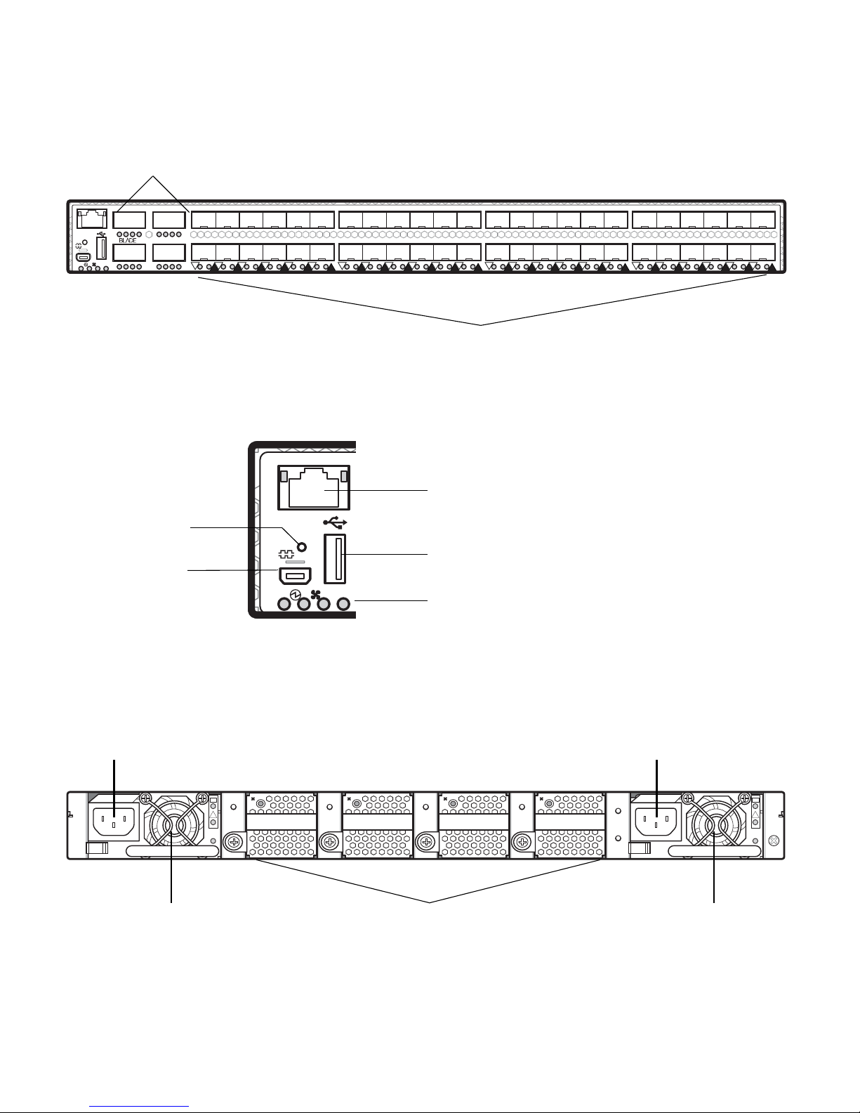
Figure 1 RackSwitch G8264 Front Panel
QSFP+ Ports
5
Mgmt
1
S
!
Reset Button
RS-232 Port
13 -16
13
5
13
8
RackSwitch G8264
9
9
102
16
124
113
715
614
1- 4 9 -12
1
40
1718192021222324252627282930313233343536373839
21
18
25 55
27 534129
3117 574533
30 56443220 60483624 64524028 5442
37
SFP+ Ports
Figure 2 RackSwitch G8264 Front Panel (Detail)
RJ-45 Port
Mgmt
!
2
RackSwitch G8264
USB Port
S
1
System Status LEDs
4142434445
4319
ABCDABCD
ABCDABCD
4647485-8
495051525354555657585960616263
49
2
1
5139
4
3
3
2
6
5
5
4
473523 63
4
1
3
64
59
61
58463422 62503826
8
7
7
6
9
8
Figure 3 RackSwitch G8264 Rear Panel
IEC320
Power Connector
OK
!
~AC
Power
Supply Module
Chapter 1: RackSwitch G8264 Description and Specifications BPP-00039-00 rev 2, January 2011
10
Fan Modules
IEC320
Power Connector
OK
!
~AC
Power
Supply Module

RackSwitch G8264 Installation
Reset Button
The Reset button is recessed within a hole on the front panel. Use a straightened paper clip or
similar object to press the Reset button. The Reset button allows technicians to reset the switch, as
follows:
Press Reset: The switch resets and reloads the configuration files.
Press and hold Reset for five seconds: The switch resets and configures all settings
to factory defaults.
Fans
Four internal fan modules cool the switch unit. If an individual fan module fails, the ot her fans
continue to run, and the switch unit continues to operate normally. These hot-swap fan modules can
be replaced by the customer.
Fan operation and internal temperatures are monitored. If the air temperature exceeds a desired
threshold, the environmental monitor displays warning messages.
Note – If a fan module fails, the maximum operating temperature drops from +40ºC to +35ºC.
The Service ( ! ) LED blinks and the Fan LED blinks if there is a failure of one or more fan modules.
The failed fan module’s LED (rear panel) blinks to indicate a failure.
AC Power Supply
The G8264 has two redundant 450W AC power supplies. Each internal power supply has an
individual IEC 320 power connector on the rear panel. The power cord attaches to a universal
grounded AC power source. Power supplies are hot-swappable and can be replaced by the
customer.
Caution—To reduce the risk of electric shock, use only power cords that have a grounding path,
and always connect the power cord to a properly grounded power outlet.
Each power supply can be connected to a separate AC circuit to mitigate the risk of down time
during a power failure. When used in a redundant configuration, the dual power supplies have a
load-sharing capability that allows each supply to operate at approximately 50 percent of full load.
Using redundant power can minimize the power disruption during a power supply failure and
extend the expected lifetime of each supply by operating normally in a conservative power mode.
There is no power switch on the G8264; the switch unit powers up when power is supplied through
the power cord(s).
The Power Supply LED indicates the status of the power supplies. The LED blinks when only one
power cord is connected, and lights steady when both power cords are connected.
BPP-00039-00 rev 2, January 2011 Chapter 1: RackSwitch G8264 Description and Specifications
11

RackSwitch G8264 Installation
Switch Ports
The RackSwitch G8264 switch ports and port options are described below.
SFP+ Ports
Forty-eight 10GbE Small Form-factor Pluggable (SFP+) ports are locat ed on the front panel.
These ports accept approved optical or copper SFP or SFP+ transceivers, or Direct Attach Cables
(DACs). Transceivers are not included with the G8264 switch unit.
The following transceivers and DACs are available from Blade Network Technologies:
Table 1 Recommended SFP Transceivers and DACs
Part number Description
BN-CKM-SP-SR SFP+ 10GBASE-SR Short Range Optical Fiber Transceiver
BN-CKM-SP-LR SFP+ 10GBASE-LR Long Range Optical Fiber Transceiver
BN-CKM-SP-ER SFP+ 10GBASE-ER Extended Range Optical Fiber Transceiver
BN-CKM-S-T SFP 1000BASE-T Copper Transceiver
BN-CKM-S-SX SFP 1000BASE-SX Short Range Fiber Transceiver
BN-CKM-S-LX SFP 1000BASE-LX Long Range Fiber Transceiver
BN-CKM-S-ZX SFP 1000BASE-ZX Extra Long Range Fiber Transceiver
BN-SP-CBL-1M SFP+ 10Gbps 1 meter DAC
BN-SP-CBL-3M SFP+ 10Gbps 3 meter DAC
BN-SP-CBL-5M SFP+ 10Gbps 5 meter DAC
BN-SP-CBL-8M5 SFP+ 10Gbps 8.5 meter DAC
Chapter 1: RackSwitch G8264 Description and Specifications BPP-00039-00 rev 2, January 2011
12

RackSwitch G8264 Installation
QSFP+ Ports
Four 40GbE Quad Small Form-factor Pluggable (QSFP+) ports are located on the front panel.
These ports accept approved optical QSFP+ transceivers or Direct Attach Cables (DACs).
BLADE QSFP+ 40GBASE-SR4 transceivers interoperate with any 40GBASE-SR4 compliant
device, and support distances up to 100 meters on OM3 fiber. Transceivers are not included with
the G8264 switch unit.
QSFP+ ports allow you to make one 40GbE connection, or four 10GbE connections, using a
breakout cable, as follows:
QSFP+ optical transceiver with MTP-to-4 LC (SFP+) fiber breakout cable.
This option supports only BLADE 10GBASE-SR SFP+ transceivers. The 40GBASE-SR4
specification (802.3ba-2010) indicates a higher optical power level than standard
10GBASE-SR. BLADE SFP+ SR transceivers can handle the higher optical power levels.
QSFP+ to four 10GbE SFP+ breakout DAC.
The SFP+ connectors on BLADE-branded breakout DACs are labelled A, B, C, and D, which
correspond to the first, second, third, and fourth ports in the port range.
The following QSFP+ transceivers and DACs are available from Blade Network Technologies:
Table 2 Recommended QSFP+ Transceivers and DACs
Part number Description
BN-CKM-QS-SR 40GBASE-SR4 QSFP+ Optical Fiber Transceiver
BN-QS-QS-CBL-1M QSFP+ 40Gbps 1 meter DAC
BN-QS-QS-CBL-3M QSFP+ 40Gbps 3 meter DAC
BN-QS-QS-CBL-5M QSFP+ 40Gbps 5 meter DAC
BN-QS-SP-CBL-1M QSFP+ to four SFP+ 1 meter breakout DAC
BN-QS-SP-CBL-3M QSFP+ to four SFP+ 3 meter breakout DAC
BN-QS-SP-CBL-5M QSFP+ to four SFP+ 5 meter breakout DAC
BPP-00039-00 rev 2, January 2011 Chapter 1: RackSwitch G8264 Description and Specifications
13

RackSwitch G8264 Installation
Console Port
The RS-232 (mini-USB) serial console port is located on the front panel. The following table
describes the pinouts for the mini-USB port:
Table 3 Console Port Pin Assignments
Pin number Function
Pin 1
Pin 2
Pin 3
Pin 4
Pin 5
No connect
RS232_SIN
RS232_SOUT
No connect
Ground
The console cable provides an RJ-45 connector (see Table 4 for RJ-45 pin assignments). A retention
clip is available to secure the console connection.
The following table describes the pin assignments for the RJ-45 connector on the console cable.
Table 4 RJ-45 Connector Pin Assignments
Pin number Signal
1 RTS (Request To Send)
2 DTR (Data Terminal Ready
3 TxD (Transmit Data)
4 GND (Ground)
5 GND (Ground)
6 RxD (Receive Data)
7 DSR (Data Set Ready)
8 CTS (Clear To Send)
The following items are also included with the console cable:
Category 5 patch cable
RJ-45 to female DB9 adapter
Chapter 1: RackSwitch G8264 Description and Specifications BPP-00039-00 rev 2, January 2011
14
RackSwitch G8264 Installation
To connect a PC or terminal to the switch, first connect the console cable to the mini-USB port on
the front panel. Connect one end of the patch cable to the RJ-45 port on the console cable, and the
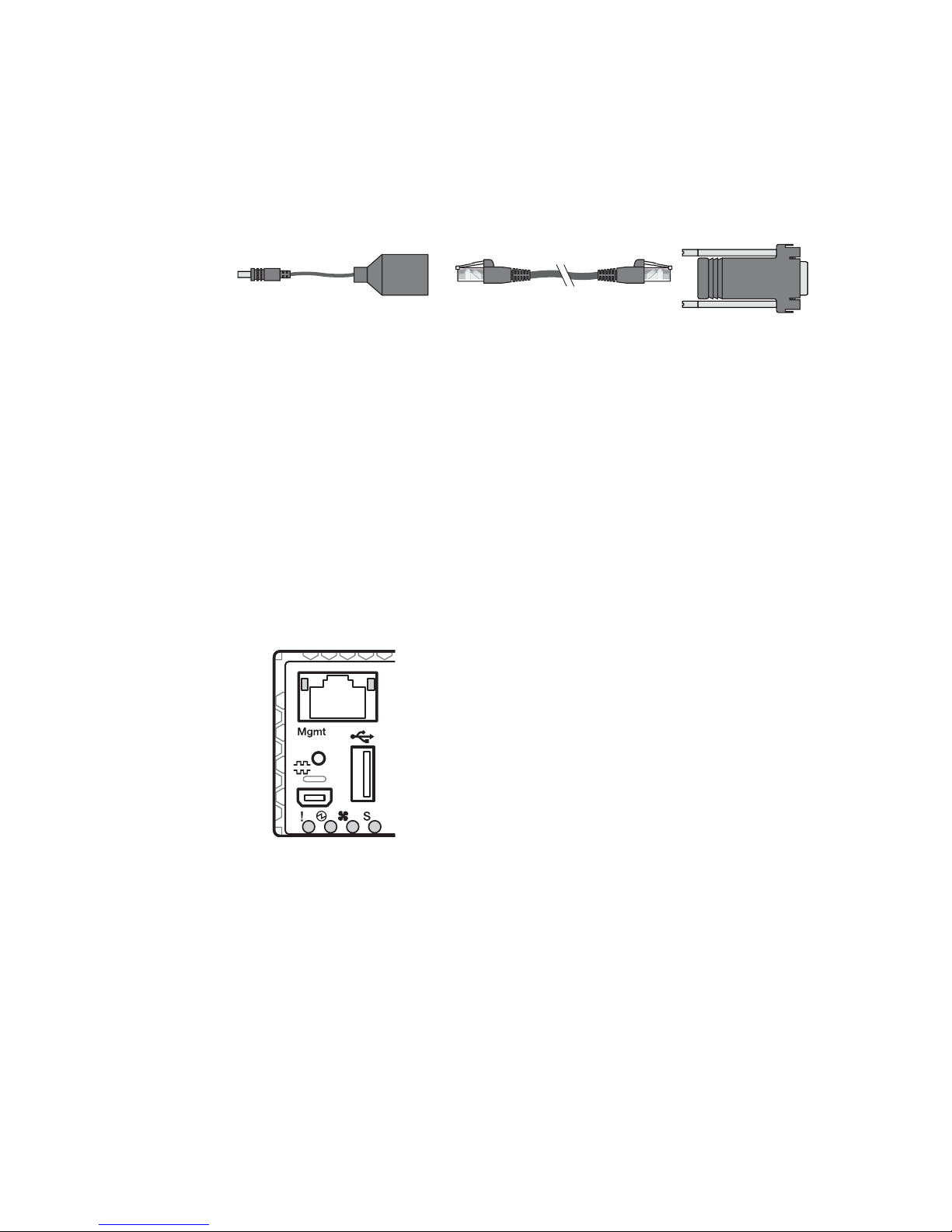
other end of the patch cable to the RJ-45-to-DB9 adapter (see Figure 4).
Figure 4 Console Cable Connections
To
Switch
Switch
Console Cable
Category 5
Patch Cable
RJ-45 Adapter
To P C
Terminal
USB Port
The USB port allows you to connect a USB drive to the switch. You can copy files from the switch
to the USB drive, or from the USB drive to the switch. You also can boot the switch using files on
the USB drive.
For more information about using the USB drive, see the RackSwitch G8264 Release Notes.
Switch LEDs
Two LED stacks provide system status and port link status. Figure 5 highlight s the system LEDs.
Figure 5 System Status LEDs
BPP-00039-00 rev 2, January 2011 Chapter 1: RackSwitch G8264 Description and Specifications
15

RackSwitch G8264 Installation
The system LEDs are described in the following ta ble:
!
Service indicator
Power supplies and power input status
Fans status
S
Stacking indicator
The following table describes the system LED indications:
Table 5 System LEDs Status
Function Service Power Supply Fans Stacking
Total Power Failure Off Off Off Off
Service Required Blink Blue Blink Green
(Note 1)
Power Supplies OK N/A Solid Green N/A N/A
Power Supply Failure Blink Blue Blink Green N/A N/A
Fans OK N/A N/A Solid Green N/A
Blink Green
(Note 2)
Blink Green or Solid
Green (Note 3)
Fan Failure Blink Blue N/A Blink Green N/A
Stack Master Off N/A N/A Blink Green
Stack Backup/Member On N/A N/A Solid Green
Stack Error Blink Blue N/A N/A Blink Green or Solid
Green
Non-Stack Member Off N/A N/A Off
Operations Command Solid Blue (Note 4) N/A N/A N/A
Note 1: If Service required is due to Power Supply Failure, this LED blinks. Otherwise it is Solid Green.
Note 2: If Service required is due to Fan Failure, this LED blinks. Otherwise it is Solid Green.
Note 3:
Note 4: If an Operations command is sent to the Unit, this LED is Solid Blue. It can be used to locate the device.
If Service required is due to a stacking error, this LED blinks or is Solid Green, depending on its last
known good state.
Chapter 1: RackSwitch G8264 Description and Specifications BPP-00039-00 rev 2, January 2011
16
RackSwitch G8264 Installation
RJ-45 LEDs
Status LEDs for the RJ-45 management port are described in the following table.
Table 6 RJ-45 LEDs Status
LED Solid Green Blink Green Off
Link Valid Link Activity No Link
Speed 100/1000Mbps N/A 10Mbps
SFP+ LEDs
Status LEDs for the SFP+ ports are described in the following table.
Table 7 SFP+ LEDs Status
Solid Green Blink Green Off
Valid Link Activity No Link
QSFP+ LEDs
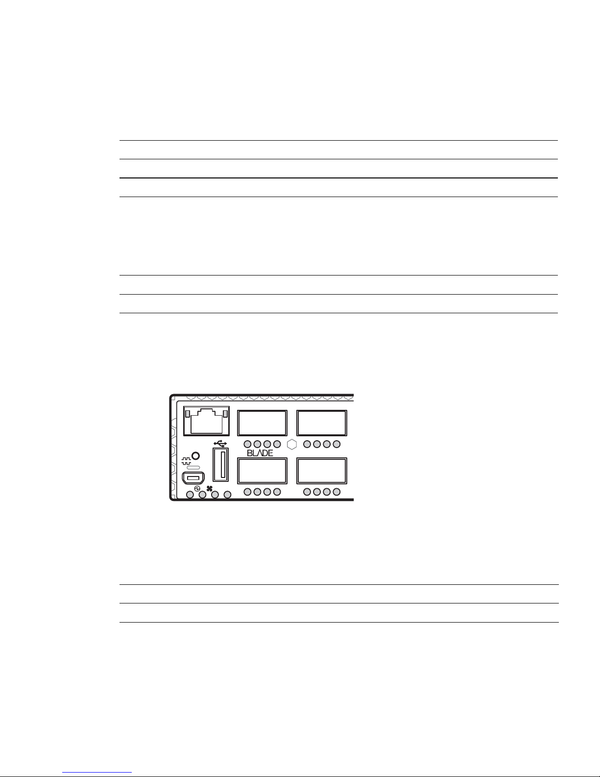
Figure 6 highlights the QSFP+ LEDs.
Figure 6 QSFP+ LEDs
Mgmt
!
5
5
614
1
S
1
13
715
13
8
RackSwitch G8264
16
9
9
124
113
102
Status LEDs for the QSFP+ ports are described in the following table. When the port is 40GbE
mode, only the first LED applies. When the port is in 4x10GbE mode, each LED provides status for
its corresponding 10GbE port, as noted in Figure 6.
Table 8 QSFP+ LEDs Status
Solid Green Blink Green Off
Valid Link Activity No Link
BPP-00039-00 rev 2, January 2011 Chapter 1: RackSwitch G8264 Description and Specifications
17

RackSwitch G8264 Installation
Technical Specifications
Physical Characteristics
Physical characteristics of the RackSwitch G8264 switch unit are listed in the following table.
Table 9 Physical Characteristics
Specification G8264F G8264R
Dimensions (H x W x D) 4.4 x 43.9 x 51.3 cm.
(1.73 x 17.3 x 20.2 in.)
Mass 10.5 kg. (maximum) 10.5 kg. (maximum)
Airflow Front-to-rear Rear-to-front
4.4 x 43.9 x 51.3 cm.
(1.73 x 17.3 x 20.2 in.)
Environmental S pecifications
Environmental specifications for the RackSwitch G8264 switch unit are listed in the following
table.
Table 10 Environmental Specifications
Specification Measurement
Temperature,
ambient operating
Temperature (fan failure),
operating
Temperature, storage -40ºC to +85ºC
Relative humidity
(non-condensing), operating
0ºC to +40ºC
0ºC to +35ºC
10 to 90%
Relative humidity
(non-condensing), storage
Altitude, operating 1,800 m
Altitude, storage 12,190 m
Acoustic noise Less than 65dB
Heat dissipation 1127 BTU/hour (typical)
Chapter 1: RackSwitch G8264 Description and Specifications BPP-00039-00 rev 2, January 2011
18
10 to 90%
(6,000 feet)
(40,000 feet)
1280 BTU/hour (maximum)

RackSwitch G8264 Installation
Power Specifications
Power specifications for the RackSwitch G8264F/G8264R switch unit are listed in the following
table.
Table 11 AC Power Specifications
Specification Measurement
Number of power supplies 2 (1+1 load sharing/redundant)
AC-input frequency (universal) 50-60 Hz
AC-input voltage (universal) 100-240 VAC
AC inrush current 15A
AC-input current (typical) 2.75A (RMS) @ 120V
1.435A (RMS) @ 230V
AC-input current (maximum) 3.125A (RMS) @ 120V
1.630A (RMS) @ 230V
Power supply rated output power 450W each
System power dissipation (typical) 330W
System power dissipation (maximum) 375W
DC-output current 23.4A (typical)
BPP-00039-00 rev 2, January 2011 Chapter 1: RackSwitch G8264 Description and Specifications
19

RackSwitch G8264 Installation
Ordering Information
The following table lists the parts that you can order for the RackSwitch G8264 product family.
Table 12 RackSwitch G8264 Ordering Information
Part number Description
BN-8264F-BDL RackSwitch G8264F GbE Switch (front-to-rear airflow)
BN-8264R-BDL RackSwitch G8264R GbE Switch (rear-to-front airflow)
BN-CKM-S-T SFP 1000BASE-T Copper Transceiver
BN-CKM-S-SX SFP 1000BASE-SX Short Range Fiber Transceiver
BN-CKM-S-LX SFP 1000BASE-LX Long Range Fiber Transceiver
BN-CKM-S-ZX SFP 1000BASE-ZX Extra Long Range Fiber Transceiver
BN-CKM-SP-SR SFP+ 10GBASE-SR Short Range Optical Fiber Transceiver
Switch
Transceivers
BN-CKM-SP-LR SFP+ 10GBASE-LR Long Range Optical Fiber Transceiver
BN-CKM-SP-ER SFP+ 10GBASE-ER Extended Range Optical Fiber Transceiver
BN-CKM-QS-SR QSFP+ 40GBASE-SR4 Optical Fiber Transceiver
Direct Attach Cables (DACs)
BN-SP-CBL-1M SFP+ 10Gbps 1 meter DAC
BN-SP-CBL-3M SFP+ 10Gbps 3 meter DAC
BN-SP-CBL-5M SFP+ 10Gbps 5 meter DAC
BN-SP-CBL-8M5 SFP+ 10Gbps 8.5 meter DAC
BN-QS-QS-CBL-1M QSFP+ 40Gbps 1 meter DAC
BN-QS-QS-CBL-3M QSFP+ 40Gbps 3 meter DAC
BN-QS-QS-CBL-5M QSFP+ 40Gbps 5 meter DAC
BN-QS-SP-CBL-1M QSFP+ to four SFP+ 1 meter breakout DAC
BN-QS-SP-CBL-3M QSFP+ to four SFP+ 3 meter breakout DAC
BN-QS-SP-CBL-5M QSFP+ to four SFP+ 5 meter breakout DAC
Rack Mounting Kits
BN-MNT-GEN-2POST RackSwitch 19” EIA 2-Post Rack Mounting Kit
BN-4Post-RLS RackSwitch 19” EIA 4-Post Rack Mounting Kit
BN-4POST-RLS-X RackSwitch 19” System-X 4-Post Rack Mounting Kit
Chapter 1: RackSwitch G8264 Description and Specifications BPP-00039-00 rev 2, January 2011
20

Table 12 RackSwitch G8264 Ordering Information
Part number Description
BN-4POST-RLS-IDP RackSwitch iDataPlex Rack Mounting Kit
Power Supply Modules
BN-82-AC-F-PSU AC Power Supply module (front-to-rear airflow)
BN-82-AC-R-PSU AC Power Supply module (rear-to-front airflow)
Fan Modules
BN-82-F-FAN Fan module (front-to-rear airflow)
BN-82-R-FAN Fan module (rear-to-front airflow)
RackSwitch G8264 Installation
BPP-00039-00 rev 2, January 2011 Chapter 1: RackSwitch G8264 Description and Specifications
21
 Loading...