

Page 1

Instruction Manual
Bedienungsanleitung
Manuel d’utilisation
Manuale di Istruzioni
Page 2

EN
Safety Precautions and Warnings
• Always keep a safe distance in all directions around your model to avoid
collisions or injury. This model is controlled by a radio signal subject to
interference from many sources outside your control. Interference can cause
momentary loss of control.
• Always operate your model in open spaces away from full-size vehicles, traffi c
and people.
• Always carefully follow the directions and warnings for this and any optional
support equipment (chargers, rechargeable battery packs, etc.).
• Always keep all chemicals, small parts and anything electrical out of the reach
of children.
• Always avoid water exposure to all equipment not specifi cally designed and
protected for this purpose. Moisture causes damage to electronics.
• Never place any portion of the model in your mouth as it could cause serious
injury or even death.
• Never operate your model with low transmitter batteries.
• Always keep aircraft in sight and under control.
• Always activate throttle hold at rotor strike.
• Always use fully charged batteries.
• Always keep transmitter powered on while aircraft is powered.
• Always remove batteries before disassembly.
• Always keep moving parts clean.
• Always keep parts dry.
• Always let parts cool after use before touching.
• Always remove batteries after use.
• Never operate aircraft with damaged wiring.
• Never touch moving parts.
Age Recommendation: Not for children under 14 years. This is not a toy.
WARNING: This is a large model helicopter with carbon fi ber blades that spin at very high RPM. Always use extreme caution and common sense when
maintaining and operating this product. If you are unsure about ANY function or procedure described in this manual, DO NOT operate. Contact Horizon
Product Support for assistance.
WARNING: Always ensure you are operating the helicopter a safe distance, 45 feet (13 meters), away from yourself and others.
WARNING: Read the ENTIRE instruction manual to become familiar with the features of the product before operating. Failure to operate the product
correctly can result in damage to the product, personal property and cause serious injury.
This is a sophisticated hobby product. It must be operated with caution and common sense and requires some basic mechanical ability. Failure to operate this
Product in a safe and responsible manner could result in injury or damage to the product or other property. This product is not intended for use by children without
direct adult supervision. Do not use with incompatible components or alter this product in any way outside of the instructions provided by Horizon Hobby, LLC. This
manual contains instructions for safety, operation and maintenance. It is essential to read and follow all the instructions and warnings in the manual, prior to assembly, setup or use, in order to operate correctly and avoid damage or serious injury.
The following terms are used throughout the product literature to indicate various levels of potential harm when operating this product:
WARNING: Procedures, which if not properly followed, create the probability of property damage, collateral damage, and serious injury OR create a high probability
of superfi cial injury.
CAUTION: Procedures, which if not properly followed, create the probability of physical property damage AND a possibility of serious injury.
NOTICE: Procedures, which if not properly followed, create a possibility of physical property damage AND a little or no possibility of injury.
NOTICE
All instructions, warranties and other collateral documents are subject to change at the sole discretion of Horizon Hobby, LLC. For up-to-date product literature,
visit horizonhobby.com and click on the support tab for this product.
Meaning of Special Language
2
Page 3
EN
To receive product updates, special offers and more, register your product at www.horizonhobby.com
Table of Contents
Length
38.6 in (980mm)
Main Rotor Diameter
43.1 in (1095mm)
Tail Rotor Diameter
9.1 in (232mm)
Components Needed to Complete ...................................................................... 3
Assembly Guide Legend ..................................................................................... 3
Tools Needed To Complete ................................................................................ 3
! BEFORE STARTING ASSEMBLY! ....................................................................... 4
Head Assembly ..................................................................................................4
Frame Assembly ................................................................................................5
Tail Assembly ................................................................................................... 11
Flight Controller Mounting ................................................................................15
Battery Installation ........................................................................................... 15
Helicopter Setup ..............................................................................................15
Main Rotor Alignment ......................................................................................16
Throttle Hold .................................................................................................... 16
Control Tests .................................................................................................... 16
Tail Rotor Blade Installation .............................................................................. 18
Main Rotor Blade Installation ...........................................................................18
Canopy Installation ..........................................................................................18
Flight Guidelines and Warnings ........................................................................ 19
Flying Your Fusion 480 ..................................................................................... 19
Blade Tracking ................................................................................................. 19
Post-Flight Inspection and Maintenance ...........................................................19
Troubleshooting Guide ..................................................................................... 20
Limited Warranty ............................................................................................. 20
Warranty and Service Contact Information .......................................................21
Exploded View ................................................................................................. 84
Parts List .........................................................................................................86
Recommended Components ............................................................................ 87
Optional Parts .................................................................................................. 87
Specifi cations
3
Recommended Component
Motor
Brushless Motor 4320-1300kV (BLH4953)
ESC
Talon 90-Amp 25V BL ESC W/20amp BEC (CSE010009700)
Battery
4400mAh 6S 22.2V 30C LiPo, 10AWG EC5 (EFLB44006S30)
Receiver
AR7210BX DSMX FBL Control System (SPMAR7210BX)
Swash Servos
H6050 Heli Cyclic Servo (SPMSH6050), metal gear servos required
Tail Servo
H6060 Heli Tail Servo (SPMSH6060), metal gear servo required
Charger
DC Li-Po Balancing Charger
Transmitter
DSM2
®
/DSMX® Compatible Transmitter
Components Needed to Complete Tools Needed To Complete
• Medium strength thread-locking compound
• High strength thread-locking compound
• 1.5mm, 2mm, 2.5mm, 3mm and 4mm hex drivers
• Ball link pliers
• Needle nose pliers
• Pitch gauge
• Metric ruler or calipers
Assembly Guide Legend
Apply NO Thread-locking Compound
Apply Medium Thread-locking Compound
Apply High Strength Thread-locking Compound
Loosely Tighten
Fully Tighten
Page 4
EN
4
Head Assembly (H)
! BEFORE STARTING ASSEMBLY!
Many of the major sub-assemblies of the Blade Fusion 480 kit have been pre-assembled at the factory. These sub-assemblies
were not assembled with thread-locking compound. Prior to beginning assembly of the kit, loosen any pre-assembled
screws which are threaded into metal components and apply thread-locking compound. Use only enough thread-locking
compound to moisten the threads. Check all pre-assembled components to ensure all fasteners are tight.
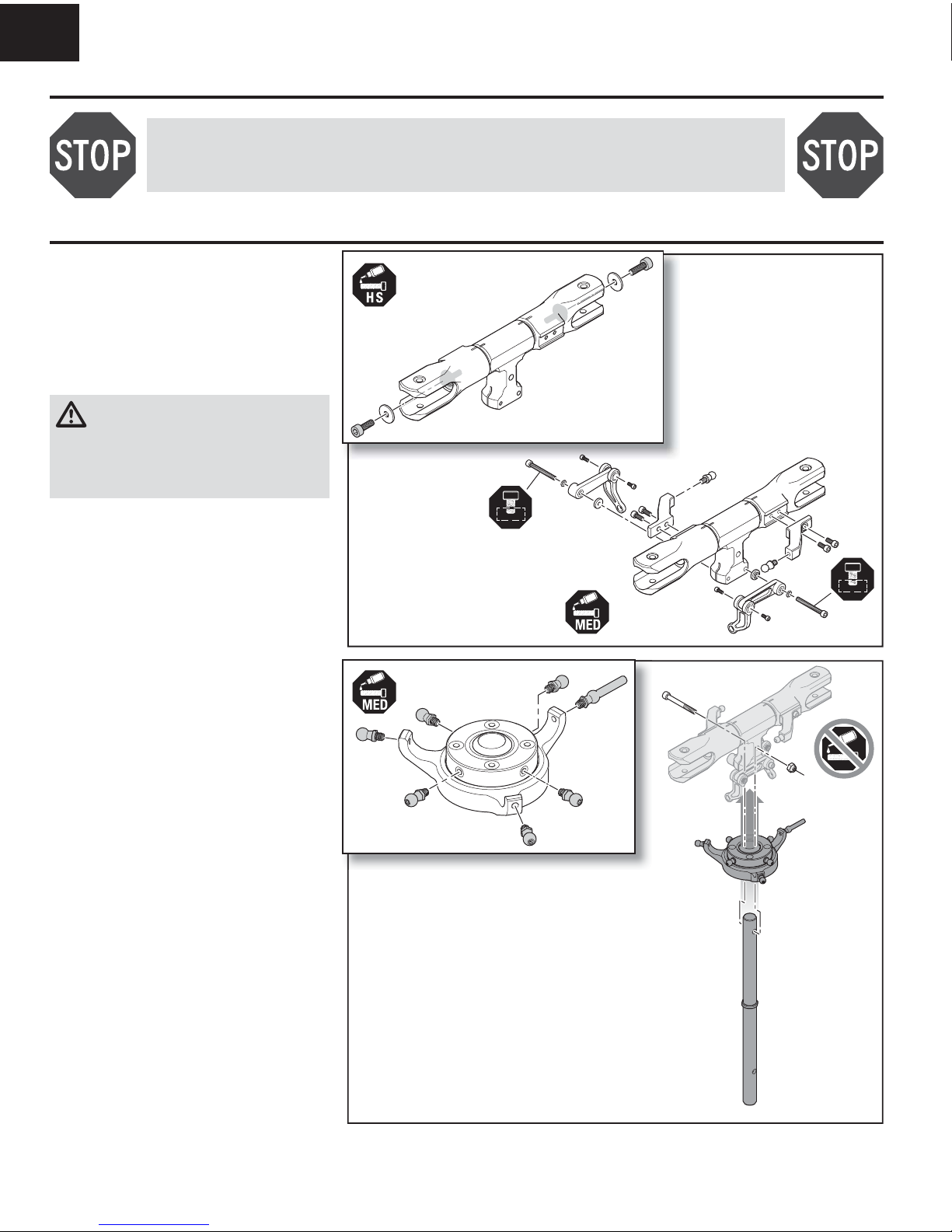
1. Remove the spindle bolts from the blade grips.
2. Clean the spindle threads and the threads of the
4x12mm spindle bolts with isopropyl alcohol.
3. Apply high strength thread-locking compound and
re-install the spindle bolts. Ensure the thread-locking
compound does not contact the blade grip bearings.
WARNING: Failure to apply high strength
thread-locking compound to the spindle bolts
may allow the spindle bolts to work free during
operation, which could cause the rotor blades to fl y
off. Projectile rotor blades pose a serious risk of
property damage and may cause severe bodily injury.
4. Remove the linkage balls from the main grip arms
and re-install them using medium thread-locking
compound.
5. Install the main grip arms to the blade grips using
two 3x10mm socket head caps crews per arm and
medium thread-locking compound.
6. Remove the 2x5mm socket head cap screws one
at a time from the follower arms and re-install with
medium thread-locking compound.
7. Install the follower arms to the head block using one
3x20mm socket head cap screw and two washers
per arm and medium thread-locking compound.
Ensure the thread-locking compound does not
contact the bearings of the follower arms. Do not
fully tighten at this time.
1. Remove the seven linkage balls from the swashplate
assembly one at a time and re-install them with
medium thread-locking compound.
2. Fit the swashplate over the main shaft.
3. Insert the main shaft into the head block and secure
it with a 4x20mm bolt and locknut. Before tightening
the bolt pull on the head block to verify the bolt
passes through the hole in the main shaft. Do not
use thread-locking compound on the head bolt
and locknut.
4. Fully tighten the two follower arm 3x20 socket head
cap screws installed in step 7 above.
Step H2
Step H1
Page 5
EN
55mm
68mm
5
Frame Assembly (F)
NOTICE: Always plan your servo wire routing prior to assembly. If servo wires will pass through or cross the frame plates, use sandpaper or a fi le to smooth the
edges of the frame plate to prevent wire chafi ng. Damage to servo wires may result in loss of control.
CAUTION: Sanding or fi ling carbon fi ber, such as frame plates, may produce carbon dust. Always wear appropriate Personal Protection Equipment (PPE)
such as a dust mask, when there is a danger of carbon dust.
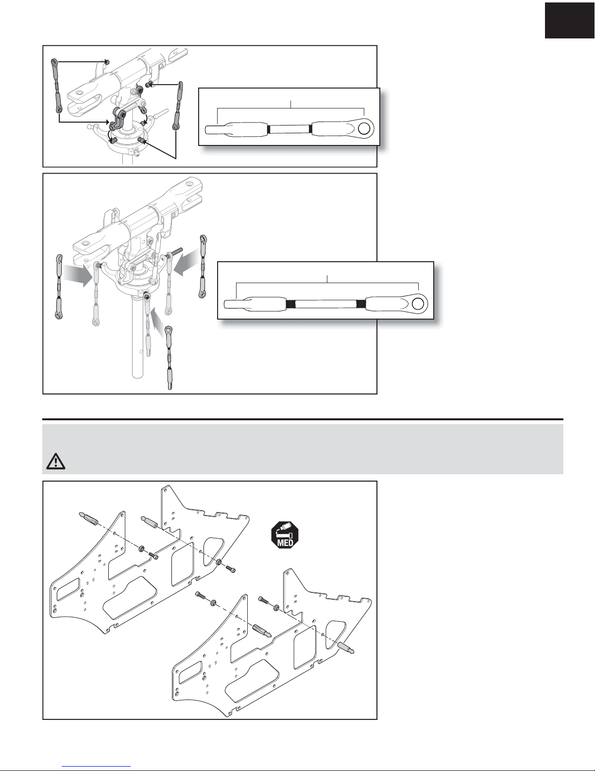
1. Snap the follower arms onto two opposite linkage
balls on the upper swashplate.
2. Adjust the length of the rotor head linkages to 55mm
from center to center of the link openings.
3. Snap the rotor head linkages onto the main grip
linkage balls.
4. Snap the other end of the linkages to the remaining
linkage balls of the upper swashplate.
1. Adjust the length of the rotor head linkages to 68mm
from center to center of the link openings.
2. Snap one end of the servo control linkages onto the
linkage balls on the lower swashplate.
Attach two canopy posts to each frame plate using
a 3x10mm screw, a machined washer and medium
thread-locking compound for each post. Assemble both
a left and right frame side as shown in the illustration.
Step F1
Step H3
Step H4
Page 6
EN
6
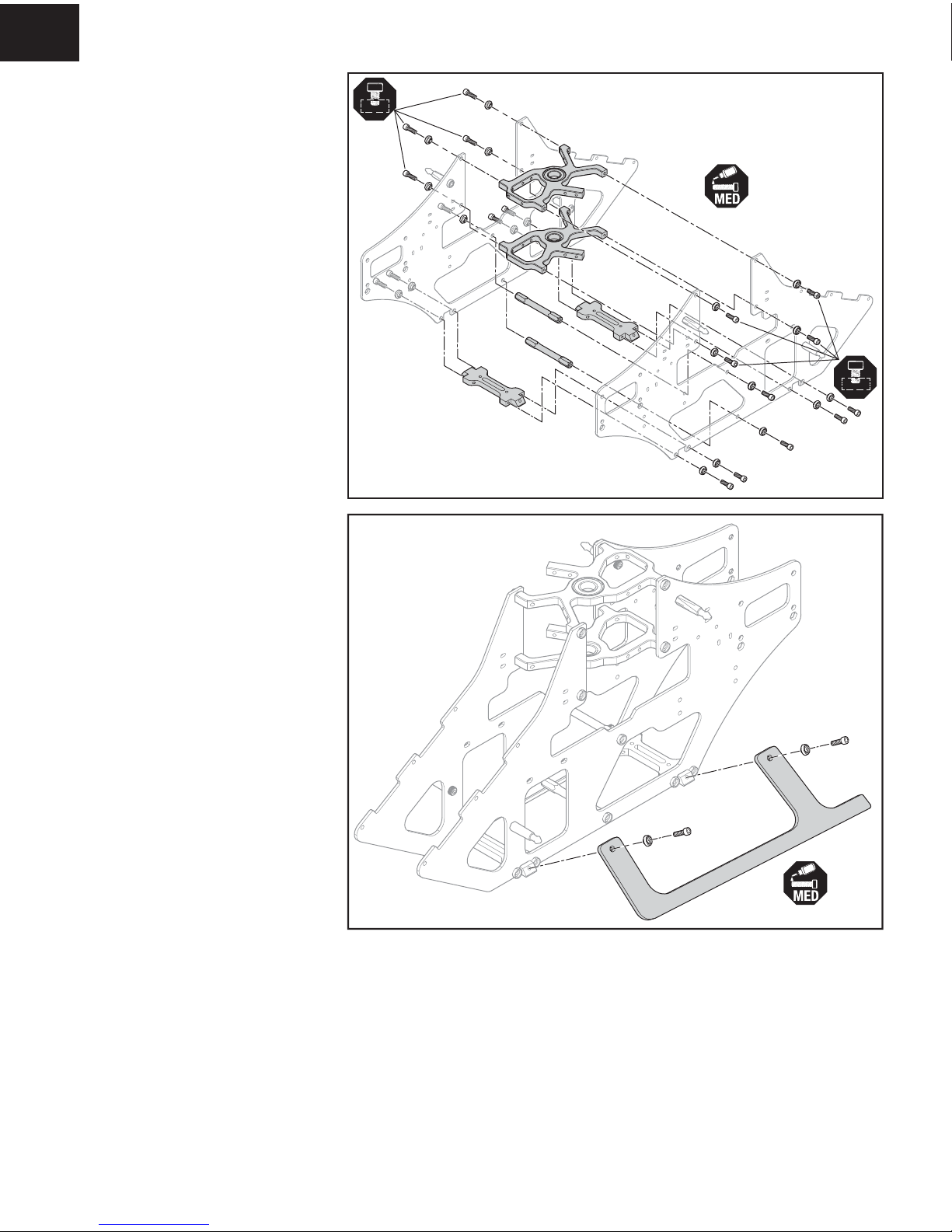
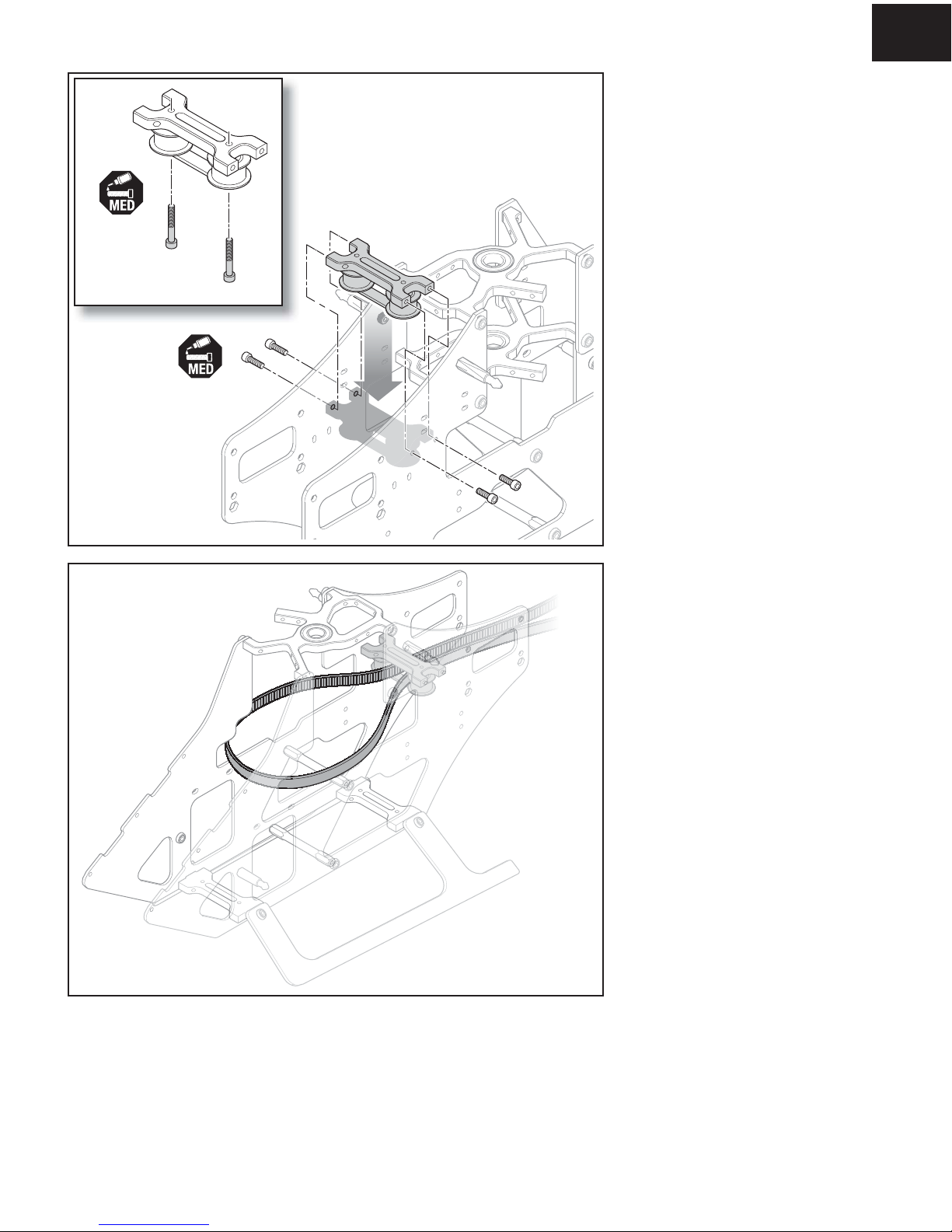
1. Attach the upper and lower bearing blocks to the
frame sides using 3x10mm screws, machined
washers and medium thread-locking compound.
The upper block has two threaded holes in the rear
of the block. Do not fully tighten the screws in the
bearing blocks at this time.
2. Slide the main shaft through both bearing blocks to
ensure the blocks are properly aligned with each
other.
3. Set the frame sides upright on a fl at surface, with
the bottom of both sides fully in contact with the
work surface.
4. Tighten all of the bearing block screws fully and
remove the main shaft from the bearing blocks.
5. Attach two landing gear mounts and two frame
posts to the frame sides using 3x10mm screws,
machined washers and medium thread-locking
compound.
Attach the landing gear to each side of the frame using
3x10mm screws, machined washers and medium
thread-locking compound.
Step F3
Step F2
Page 7
EN
7
Frame side removed for clarity
1. Remove the 3x18mm socket head cap screws of
the tail belt guide assembly and re-install them
using medium thread-locking compound. Ensure
the thread-locking compound does not contact the
bearings of the tail guide assembly.
2. Install the tail belt guide between the frame sides
using 3x10mm screws and medium thread-locking
compound.
Thread the tail belt through the belt guide with the teeth
of the belt facing inward. Pull enough of the belt through
the guide to form a large loop, as shown.
Be careful to not crimp the belt.
Step F4
Step F5
Page 8
EN
8
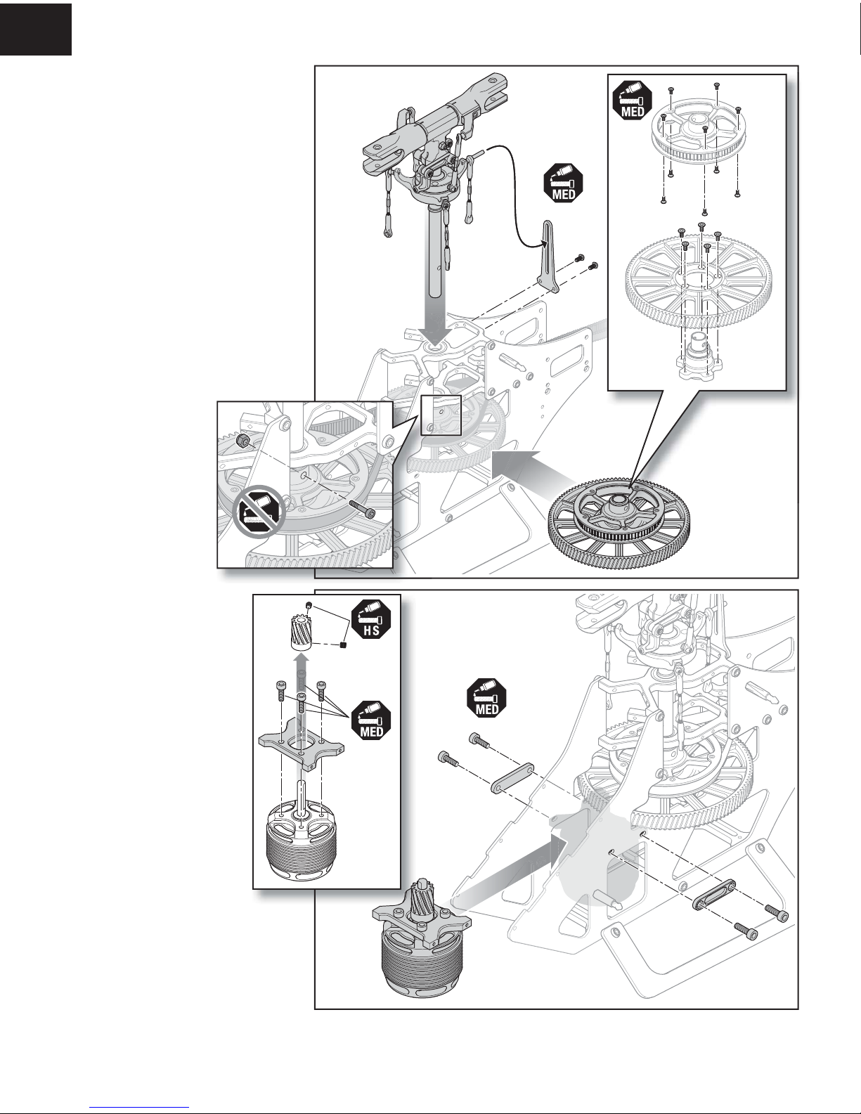
1. Pull the tail belt pulley off of the one-way bearing
sleave. Remove ten 2x4mm fl athead screws from
the tail drive pulley one at a time and re-install them
using medium thread-locking compound.
2. Remove fi ve 3x6mm fl athead screws one at a time
from the main gear and re-install them using medium
thread-locking compound. Re-install the tail belt pulley
on the one-way bearing sleave, ensuring the hole in the
pulley aligns with the holes in the sleave.
3. Slide the main gear assembly through the side of the
frame.
4. Place the tail belt around the upper gear as shown.
5. Slide the rotor head assembly down through both
bearing blocks and the main gear assembly.
6. Secure the main gear to the main shaft using a
4x20mm bolt and lock nut. Do not use thread-
locking compound on the bolt and lock nut.
7. Attach the anti-rotation bracket to the back of the
upper bearing block using two
M3x6mm button head screws
and medium thread-locking
compound. Ensure the antirotation pin is facing the rear
of the frame and is inserted in
the bracket before securing the
bracket to the bearing block.
8. Rotate the rotor head to ensure
it rotates freely.
1. Attach your chosen motor to the motor
mount using four 3x8mm screws and
medium thread-locking compound. The
motor leads should face toward the front
of the aircraft when installed.
2. Attach the pinion gear to the motor shaft
using two 4x4mm setscrews and high
strength thread-locking compound.
3. Prepare the motor leads for connecting
to the speed control. If using the
recommended speed control, solder the
large bullet connectors to the motor leads.
4. Attach the motor mount assembly
between the frame sides using
M3x10mm screws, machined frame
doublers and thread-locking compound.
Step F5
Step F6
Page 9

EN
9
1. If using the recommended speed control, attach the
speed control mount, included with the speed control,
to the bottom side of the battery plate. Secure a hook
and loop strap between the battery plate and the
speed control mount, as shown.
2. Clip the speed control in the speed control mount.
3. Connect the motor leads to the speed control.
4. Attach the battery mounting plate between the frame
sides using six 3x10mm screws and medium threadlocking compound. Place a second hook and loop
strap under the plate. The straps should exit through
the gaps in the frame sides.
Hook and
loop straps
Hook and
loop strap
Step F7
Page 10

EN
20mm
16mm
10
Prepare three cyclic servos as follows:
1. Center the servos using either your receiver or a
servo tester.
2. Attach the servo arm in the position shown,
perpendicular to the servo case, using the screw
provided with the servo and medium thread-locking
compound.
3. Attach the linkage ball to the outer servo arm
location using an M2 nut.
4. Attach the servos to the bearing blocks, in the
positions shown using 3x10mm button head screws
and medium thread-locking compound.
5. Press the bottom end of the servo linkages on the
servo arm linkage balls.
Prepare the tail servo as follows:
1. Center the servo using either your receiver or a
servo tester.
2. Attach the servo arm in the position shown,
perpendicular to the servo case, using the screw
provided with the servo and medium thread-locking
compound.
3. Attach the linkage ball to the middle servo arm
location, using an M2 nut.
4. Attach the tail servo mounts to the servo using
M3x8mm button head screws and thread-locking
compound. Do not fully tighten the servo mount
screws.
5. Attach the tail servo assembly to the inside of the
right frame side as shown, using four 3x10mm
screws, machined washers and medium threadlocking compound.
6. Fully tighten the servo mount screws.
Rotor head removed for clarity
Step F8
Step F9
Page 11

EN
11
Tail Assembly (T)
1. Slide two front tailboom mounts over the front of the
tail boom. The Blade
®
logo is towards the front of
the tailboom.
2. Attach the mounts to the tailboom using one
M3x6mm button head screw per mount and
medium thread-locking compound, into the holes in
the top of the tailboom.
3. Loosely insert a 3x12mm screw and locknut into the
bottom of each mount. Do not use thread-locking
compound. Do not fully tighten.
4. Insert the free end of the tail belt through the
tailboom.
5. Feed the belt through the boom as you slide the
boom mounts between the frame sides.
6. Attach the boom mounts to the frame sides using
3x10mm screws, machined washers and medium
thread-locking compund.
7. Fully tighten the 3x12mm boom mount screws and
locknuts installed in Step 3 above.
8. When the boom is fully seated in place, the tail
belt should extend from the back of the boom as
shown. Rotate the rear loop of the belt 90° counterclockwise from horizontal, when viewed from the
rear of the aircraft. Ensure the belt is not twisted
inside the boom.
Step T1
Viewed from the rear of the helicopter
Page 12

EN
12
Tail Assembly (T)
1. Slide the tail pushrod guide onto the tailboom. The
guide should be located approximately in the center
of the tailboom.
1. Remove the 3x16mm socket head cap screw and
linkage ball from the tail pitch lever assembly
and re-install them using medium thread-locking
compound. Ensure the thread-locking compound
does not contact the lever assembly bearings.
2. Attach the tail rotor pitch lever assembly to the
right side tail plate using two 2.5x8mm button head
screws and medium thread-locking compound.
3. Attach the right tail plate assembly to the tailboom
mounts using four 3x10mm socket head capscrews,
machined washers and medium thread-locking
compound. Do not fully tighten.
4. Attach the left side tail plate/fi n to the tailboom
mounts using four 3x10mm socket head capscrews,
machined washers and medium thread-locking
compound. Do not fully tighten.
5. Insert the tail belt guide bearing between the tail
plates and attach with two 2.5x8mm socket head
capscrews and medium thread-locking compound.
6. Insert the rear spacer post between the tail
plates and attach with two 3x10mm socket head
capscrews, machined washers and medium threadlocking compound.
2. Slide two rear tailboom mounts over the tailboom.
3. Attach the mounts using two 3x6mm button head
screws per mount and medium thread-locking
compound, into the holes on either side of the tailboom.
4. Loosely insert one 3x10mm socket head capscrew
with medium thread-locking compound in the top of
each mount as shown.
Step T2
Step T3
Page 13

EN
13
Tail Assembly (T)
1. Remove the tail grip retention screws and linkage
balls and re-install them using medium threadlocking compound. Ensure the thread-locking
compound does not contact the tail grip bearings.
2. Insert the tail shaft into the tail rotor hub assembly.
3. Lock the tail shaft into place with a M4x4mm
setscrew and high strength thread-locking
compound. Ensure the setscrew contacts the fl at
area machined into the tail shaft.
4. Remove the linkage ball from the pitch slider assembly
and re-install using medium thread-locking compound.
5. Slide the pitch slider assembly over the tail shaft and
snap the ball links onto the tail grip linkage balls.
1. Remove four 2x16mm cap head screws from the
tail pulley one at a time and re-install using medium
thread-locking compound.
2. Insert the tail pulley into the loop created by the tail
belt, as shown.
3. Slide the tail shaft in from the right side, through the
tail pulley and into the left side tail plate bearing. As
you slide the tail shaft in, insert the linkage ball of
the tail pitch slider into the nylon bushing of the tail
rotor bell crank.
4. The tail shaft should extend out of the left side plate
bearing by approximately 1mm.
5. Secure the tail pulley to the tail shaft using two
4x4mm setscrews and medium thread-locking
compound. Ensure the setscrews are in contact with
the fl at areas machined into the tail shaft.
Check the rotation of the tail pulley. The tail pulley
should rotate as shown when the main rotor is rotated
clockwise, when viewed from above. If the tail gear
does not rotate as shown, remove the tail shaft and tail
pulley, rotate the tail belt loop 180° and re-assemble.
Sight down the tail boom and ensure the tail belt is
not twisted more than 90° inside the tail boom.
Step T4
Step T5
Page 14

EN
14
Tail Assembly (T)
1. Check the belt tension just behind the main gear at
the rear of the side plate opening. Push inward on
the belt from the side with moderate pressure. The
belt should not defl ect more 4mm.
2. Set the tail belt tension by applying pressure against
both tail side plates towards the rear of the aircraft.
Fully tighten the eight 3x10mm screws holding the
tail side plates to the rear boom mounts.
1. Insert the metal sleeve of the tail pushrod into the
pushrod guide.
2. Secure the pushrod guide with a socket head cap
screw.
3. Snap the front tail pushrod linkage onto the tail
servo arm.
4. Snap the rear pushrod linkage onto the tail rotor
pitch lever.
Step T6
Step T7
Page 15

EN
15
Flight Controller Mounting
Battery Installation
1. Route the servo and throttle wires to the fl ight
controller mounting area of the frame. Small holes are
provided in the frame side plates to allow for securing
the servo wires with small plastic cable ties. When
routing the wires, be very careful to avoid any moving
parts and sharp edges of the carbon fi ber plates.
2. Attach the fl ight controller mounting plate to the top
of the front tail boom mounts using four M3x6mm
fl athead screws and thread-locking compound.
3. Secure your chosen fl ybarless fl ight controller to
the mounting plate per the mounting instructions
included with your fl ight controller.
4. Connect the servo and throttle wires to the fl ight
controller.
1. Apply the loop side of adhesive backed hook and loop
material to the fl ight battery.
2. Apply the hook side to the battery plate.
3. Attach the fl ight battery to the battery plate.
4. Secure the battery with the hook and loop straps.
CAUTION: Always disconnect the Li-Po
battery from the electronic speed control
when not fl ying to avoid over-discharging the battery.
Batteries discharged to a voltage lower than the
lowest approved voltage may become damaged,
resulting in loss of performance and potential fi re
when batteries are charged.
Loop
material
Hook
material
Hook and
loop straps
Helicopter Setup
The following are optimal settings for the Blade Fusion 480, obtained through extensive fl ight testing. Refer to your fl ybarless fl ight controller and transmitter manuals for
proper setup.
Head Speed
Flight Mode 11t Pinion
Optional 12t Pinion
(only recommended for 65C batteries)
Normal 2100 2100
Stunt 1 2350 2550
Stunt 2 2550 2750
Collective Pitch Range
Normal, -12 degrees to +12 degrees
(adjust to suit your preferences)
Page 16

EN
Throttle Hold
Control Tests
16
Main Rotor Alignment
Activating and using the Throttle Hold (TH HOLD) function in your chosen
transmitter is highly recommended. Throttle hold only cuts power to the motor on
an electric helicopter. Pitch and direction control are maintained.
WARNING: If your transmitter has throttle hold, always engage throttle
hold before approaching the helicopter for any reason.
The blades will spin if TH HOLD is OFF. For safety, turn TH HOLD ON any time you
need to touch the helicopter or check the direction controls.
Additionally, turn TH HOLD ON to cut power to the motor if the helicopter is out of
control, in danger of crashing, or both.
With the servos centered and arms level, the
swashplate should be level and the 0 degree collective
indication marks on top of the blade grips and
headblock should align, as shown. Adjust the lengths
of the blade grip linkages and servo linkages until
everything is aligned properly.
Cyclic Sensor Test
From the back of the helicopter:
1. Tilt the helicopter forward. The swashplate should tilt backward.
2. Tilt the helicopter backward. The swashplate should tilt forward.
3. Roll the helicopter left. The swashplate should roll right.
4. Roll the helicopter right. The swashplate should roll left.
5. If the swashplate does not move in the correct direction, you will need to
reverse the cyclic sensor direction or sensor orientation setting. Refer to the
fl ight controller manual for information.
CAUTION: You must complete the Rudder and Cyclic tests prior to attempting fl ight. Failure to ensure the sensor directions are not reversed can cause the
helicopter to crash, resulting in property damage and injury.
Rudder
1. Power on the transmitter.
2. Turn TH HOLD ON and set the fl ight mode to NORMAL.
3. Connect the helicopter battery to the ESC and allow the fl ight controller to
fully initialize.
4. Rudder channel test:
Move the rudder stick to the right. The tail pitch slider should move towards
the tail boom.
Move the rudder stick to the left. The tail pitch slider should move away from
the tail boom.
If the slider does not move in the desired direction, refer to your fl ight
controller manual for instructions to correct the issue.
5. Flight controller sensor test:
Release the rudder control. Manually turn the helicopter counterclockwise when
viewed from above. The tail pitch slider should move towards the tail boom.
Manually turn the helicopter nose clockwise. The tail pitch slider should move
away from the tail boom.
If the slider does not react in the proper direction, refer to your fl ight controller
manual for information on reversing the tail sensor direction.
Page 17

EN
Cyclic and Collective Control Test
Turn TH HOLD ON when conducting the control tests. Increasing Collective Pitch while TH HOLD is off will cause the motor to engage and the rotors to spin.
Elevator, Forward and Back Cyclic
Aileron, Left and Right Cyclic
Rear ViewRear View
Collective Pitch
Left Side View Left Side View
Left Side View Left Side View
17
Motor Direction Test
Place the helicopter outdoors on a clean, fl at and level surface (concrete or asphalt) free of obstructions. Always stay clear of rotating parts.
1. Power on the transmitter. Make sure TH HOLD is ON and the fl ight mode
switch is set to NORMAL.
WARNING: The motor and rotors will spin when throttle is increased
and THHOLD is OFF.
2. Lower the throttle completely.
3. Connect the Li-Po battery to the ESC.
4. Turn TH HOLD OFF. Slowly increase the throttle until the drive train begins
to turn. The main rotor should spin clockwise when viewing the helicopter
from the top. The tail rotor should spin counterclockwise when viewing the
helicopter from the right side.
NOTICE: If the drive train does not turn with the motor or the main rotor
spins counterclockwise, turn TH HOLD ON. Disconnect the battery from the
helicopter and reverse any two motor wire connections to the ESC and repeat
the motor control test.
Thoroughly review your chosen fl ight control system manual to ensure the system is confi gured properly, per the manufacturer’s recommendations.
WARNING: Disconnect the motor from the electronic speed control or ensure the transmitter throttle hold function is properly confi gured and ON prior to
performing the cyclic and collective control tests. Failure to do so will allow the motor to start unexpectedly and may cause serious property damage or
bodily injury.
Page 18

EN
18
Main Rotor Blade Installation
Canopy Installation
Install the main rotor blades in the orientation shown
using 4x30mm bolts, plastic blade shims and locknuts.
Do not apply thread lock compound to the bolt and
lock nut.
Do not over-tighten.
• The rotor blades should be tight enough to hold their
position if you hold the helicopter sideways and
remain in position even if the helicopter is shaken
abruptly. The exact tension is not as important as
ensuring both blades are at the same tension.
Tail Rotor Blade Installation
Install the tail blades in the orientation shown using
3x12mm bolts and locknuts. Do not apply thread lock
compound to the bolt and lock nut.
1. Install the four canopy grommets into the canopy
from the inside.
2. Install the canopy by sliding the canopy grommets
over the corresponding canopy posts as shown.
Page 19

EN
Flight Guidelines and Warnings
• Always keep aircraft in sight and under control.
• Always keep people and pets at least 45 feet (13 meters) away when the
battery is connected.
• Keep children out of the vicinity of this product at all times.
• Always turn on throttle hold prior to a rotor strike.
• Always use fully charged batteries.
• Always keep transmitter powered on while the aircraft is powered on.
• Always remove batteries before disassembly.
• Always keep moving parts clean.
• Always keep parts dry.
• Always let parts cool after use before touching.
• Always remove batteries after use.
• Always have a fi rst aid kit with you.
• Always have an appropriate fi re extinguisher with you.
• Never operate aircraft with damaged wiring.
• Never touch moving parts.
Post-Flight Inspection and Maintenance
Ball Links
Make sure the plastic ball link holds the control ball, but is not tight (binding) on the ball. When a link is too loose on the ball, it can separate
from the ball during fl ight and cause a crash. Replace worn ball links before they fail.
Cleaning Make sure the battery is not connected before cleaning. Remove dust and debris with a soft brush or a dry lint-free cloth.
Bearings Replace bearings when they become notchy (sticky in places when turning) or draggy.
Wiring Make sure wiring does not block moving parts. Replace damaged wiring and loose connectors.
Fasteners
Make sure there are no loose screws, other fasteners or connectors. Do not over tighten metal screws in plastic parts. Tighten screws so
parts are mated together, then turn screw only 1/8th of a turn more.
Rotors
Make sure there is no damage to rotor blades and other parts which move at high speed. Damage to these parts includes cracks, burrs, chips
or scratches. Replace damaged parts before fl ying.
Flight Controller
Make sure the fl ight controller is securely attached to the frame. Replace the double-sided tape when necessary. The helicopter will crash if
the fl ight controller separates from the helicopter frame.
Gear
Make sure the gears are all in good condition. Watch for chipped teeth or excessive wear. Dust around gears is an indication of excess wear.
Replace damaged gears before fl ying.
19
CAUTION: The Blade Fusion 480 is intended for pilots with experience
fl ying aerobatic, collective pitch helicopters. The Blade Fusion 480 is more
responsive than other Blade helicopters. If you are not an experienced 3D or
collective pitch helicopter pilot, do not attempt to fl y this product.
NOTICE: To minimize damage, always activate throttle hold prior to or during
a crash.
WARNING: Only use Blade Fusion 480 approved carbon fi ber main
blades. Do not use wooden main blades with the Blade Fusion 480.
Using wooden main blades may cause injury or property damage.
Consult local laws and ordinances before choosing a location to fl y your
aircraft.
Select a large, open area away from people and objects. Your fi rst fl ights should
be outdoors in low-wind conditions. Always stay at least 45 feet (13 meters)
away from the helicopter when it is fl ying.
Do not attempt to fl y the Blade Fusion 480 indoors.
Flying Your Fusion 480
Blade Tracking
WARNING: Always maintain a safe distance of at least 13 meters
(45feet) when checking the main rotor blade tracking.
WARNING: Always wear protective safety glasses when checking the
main rotor blade tracking.
To check the blade tracking:
1. Put the helicopter in a hover at an altitude near eye height.
2. Watch the movement at the blade tips. Both blades should travel in the same plane.
3. If one blade tip appears to be higher than the other, land the helicopter,
disconnect the fl ight battery and adjust the blade linkages.
4. Repeat Steps 1 through 3 until both blades are moving in the same plane.
WARNING: Disconnect and remove the fl ight battery prior to performing any troubleshooting or maintenance. Failure to do so may cause serious injury if
the motor starts unexpetedly or if the battery or ESC connections are shorted.
Page 20

EN
Troubleshooting Guide
Problem Possible Cause Solution
Helicopter power is lacking
Flight battery has low voltage Fully charge the fl ight battery
Flight battery is old or damaged Replace the fl ight battery
Flight battery cells are unbalanced Fully charge the fl ight battery, allowing the charger time to balance the cells
Helicopter will not lift off
Transmitter settings are not correct Check throttle and pitch curve settings and pitch control direction
Flight battery has low voltage Fully charge the fl ight battery
Main rotor blades are installed backwards Install the main rotor blades with the thicker side as the leading edge
The helicopter tail spins
out of control
Rudder control and/or sensor direction reversed Make sure the rudder control and the rudder sensor are operating in the correct direction
Tail servo is damaged Check the rudder servo for damage and replace if necessary
Tail drive gears are damaged Replace damaged gears.
Inadequate control arm throw Check the rudder control arm for adequate travel and adjust if necessary
The helicopter wobbles in fl ight
Cyclic gain is too high Decrease gain on the fl ight controller
Headspeed is too low
Increase the helicopter's head speed via your transmitter settings
and/or using a freshly charged fl ight pack
What this Warranty Covers
Horizon Hobby, LLC, (Horizon) warrants to the original purchaser that the product
purchased (the “Product”) will be free from defects in materials and workmanship at
the date of purchase.
What is Not Covered
This warranty is not transferable and does not cover (i) cosmetic damage, (ii)
damage due to acts of God, accident, misuse, abuse, negligence, commercial use, or
due to improper use, installation, operation or maintenance, (iii) modifi cation of or to
any part of the Product, (iv) attempted service by anyone other than a Horizon Hobby
authorized service center, (v) Product not purchased from an authorized Horizon
dealer, (vi) Product not compliant with applicable technical regulations, or (vii) use
that violates any applicable laws, rules, or regulations.
OTHER THAN THE EXPRESS WARRANTY ABOVE, HORIZON MAKES NO OTHER
WARRANTY OR REPRESENTATION, AND HEREBY DISCLAIMS ANY AND ALL IMPLIED
WARRANTIES, INCLUDING, WITHOUT LIMITATION, THE IMPLIED WARRANTIES
OF NON-INFRINGEMENT, MERCHANTABILITY AND FITNESS FOR A PARTICULAR
PURPOSE. THE PURCHASER ACKNOWLEDGES THAT THEY ALONE HAVE
DETERMINED THAT THE PRODUCT WILL SUITABLY MEET THE REQUIREMENTS OF
THE PURCHASER’S INTENDED USE.
Purchaser’s Remedy
Horizon’s sole obligation and purchaser’s sole and exclusive remedy shall be that
Horizon will, at its option, either (i) service, or (ii) replace, any Product determined by
Horizon to be defective. Horizon reserves the right to inspect any and all Product(s)
involved in a warranty claim. Service or replacement decisions are at the sole
discretion of Horizon. Proof of purchase is required for all warranty claims. SERVICE
OR REPLACEMENT AS PROVIDED UNDER THIS WARRANTY IS THE PURCHASER’S
SOLE AND EXCLUSIVE REMEDY.
Limitation of Liability
HORIZON SHALL NOT BE LIABLE FOR SPECIAL, INDIRECT, INCIDENTAL OR
CONSEQUENTIAL DAMAGES, LOSS OF PROFITS OR PRODUCTION OR COMMERCIAL
LOSS IN ANY WAY, REGARDLESS OF WHETHER SUCH CLAIM IS BASED IN
CONTRACT, WARRANTY, TORT, NEGLIGENCE, STRICT LIABILITY OR ANY OTHER
THEORY OF LIABILITY, EVEN IF HORIZON HAS BEEN ADVISED OF THE POSSIBILITY
OF SUCH DAMAGES. Further, in no event shall the liability of Horizon exceed the
individual price of the Product on which liability is asserted. As Horizon has no
control over use, setup, fi nal assembly, modifi cation or misuse, no liability shall be
assumed nor accepted for any resulting damage or injury. By the act of use, setup or
assembly, the user accepts all resulting liability. If you as the purchaser or user are
not prepared to accept the liability associated with the use of the Product, purchaser
is advised to return the Product immediately in new and unused condition to the
place of purchase.
Law
These terms are governed by Illinois law (without regard to confl ict of law principals).
This warranty gives you specifi c legal rights, and you may also have other rights
which vary from state to state. Horizon reserves the right to change or modify this
warranty at any time without notice.
WARRANTY SERVICES
Questions, Assistance, and Services
Your local hobby store and/or place of purchase cannot provide warranty support
or service. Once assembly, setup or use of the Product has been started, you
must contact your local distributor or Horizon directly. This will enable Horizon
to better answer your questions and service you in the event that you may need
any assistance. For questions or assistance, please visit our website at www.
horizonhobby.com, submit a Product Support Inquiry, or call the toll free telephone
number referenced in the Warranty and Service Contact Information section to speak
with a Product Support representative.
Inspection or Services
If this Product needs to be inspected or serviced and is compliant in the country
you live and use the Product in, please use the Horizon Online Service Request
submission process found on our website or call Horizon to obtain a Return
Merchandise Authorization (RMA) number. Pack the Product securely using a
shipping carton. Please note that original boxes may be included, but are not
designed to withstand the rigors of shipping without additional protection. Ship via a
carrier that provides tracking and insurance for lost or damaged parcels, as Horizon
is not responsible for merchandise until it arrives and is accepted at our facility.
An Online Service Request is available at http://www.horizonhobby.com/content/
service-center_render-service-center. If you do not have internet access, please
contact Horizon Product Support to obtain a RMA number along with instructions
for submitting your product for service. When calling Horizon, you will be asked to
provide your complete name, street address, email address and phone number
where you can be reached during business hours. When sending product into
Horizon, please include your RMA number, a list of the included items, and a brief
summary of the problem. A copy of your original sales receipt must be included for
warranty consideration. Be sure your name, address, and RMA number are clearly
written on the outside of the shipping carton.
NOTICE: Do not ship LiPo batteries to Horizon. If you have any issue with a LiPo
battery, please contact the appropriate Horizon Product Support offi ce.
Warranty Requirements
For Warranty consideration, you must include your original sales receipt verifying the
proof-of-purchase date. Provided warranty conditions have been met, your Product
will be serviced or replaced free of charge. Service or replacement decisions are at
the sole discretion of Horizon.
Limited Warranty
20
Page 21

EN
Warranty and Service Contact Information
Non-Warranty Service
Should your service not be covered by warranty, service will be completed and
payment will be required without notifi cation or estimate of the expense unless the
expense exceeds 50% of the retail purchase cost. By submitting the item for service
you are agreeing to payment of the service without notifi cation. Service estimates
are available upon request. You must include this request with your item submitted
for service. Non-warranty service estimates will be billed a minimum of ½ hour of
labor. In addition you will be billed for return freight. Horizon accepts money orders
and cashier’s checks, as well as Visa, MasterCard, American Express, and Discover
cards. By submitting any item to Horizon for service, you are agreeing to Horizon’s
Terms and Conditions found on our website http://www.horizonhobby.com/content/
service-center_render-service-center.
ATTENTION: Horizon service is limited to Product compliant in the
country of use and ownership. If received, a non-compliant Product will
not be serviced. Further, the sender will be responsible for arranging
return shipment of the un-serviced Product, through a carrier of the
sender’s choice and at the sender’s expense. Horizon will hold noncompliant Product for a period of 60 days from notifi cation, after which it
will be discarded.
10/15
Country of Purchase Horizon Hobby Contact Information Address
United States of America
Horizon Service Center
(Repairs and Repair Requests)
servicecenter.horizonhobby.com/RequestForm/
1608 Interstate Drive
Champaign, IL 61822
Horizon Product Support
(Product Technical Assistance)
productsupport@horizonhobby.com
877-504-0233
Sales
websales@horizonhobby.com
800-338-4639
European Union
Horizon Technischer Service service@horizonhobby.eu
Hanskampring 9
D 22885 Barsbüttel, Germany
Sales: Horizon Hobby GmbH +49 (0) 4121 2655 100
21
Page 22

Exploded View / Explosionszeichnung / Vue éclatée / Vista esplosa
17
9
12
15
16
47
47
46
11
8
10
7
1
2
2
3
3
1
5
5
6
7
8484
Page 23

Exploded View / Explosionszeichnung / Vue éclatée / Vista esplosa
13
22
25
14
29
18
18
27
27
18
28
49
26
24
30
34
35
32
36
37
38
41
43
45
44
44
42
39
39
33
31
40
24
24
24
21
21
19
20
48
23
8585
Page 24

Parts List / Ersatzteile / Pièces de rechange / Pezzi di ricambio
8686
# Part # English Deutsch Français Italiano
1
BLH4901 480mm CF Main Rotor Blades (2) 480mm CF Hauptrotorblätter (2) Pales du rotor principal 480mm CF (2) Pale rotore principale 480 mm CF (2)
2
BLH4902 Main Rotor Grip Hauptrotorhalter Poignée du rotor principal Fermo rotore principale
3
BLH4903 Grip Arm Halterarm Poignée Braccio fermo
4
BLH4904 Spindle Spindel Axe Fuso
5
BLH4905 Dampener Set Stoßdämpfersatz Ensemble d’amortisseur Set ammortizzatori
6
BLH4906 Aluminum Head Block Aluminium-Kopfblock Bloc de tête en aluminium Blocco di testa in alluminio
7
BLH4907 Follower Arm Folgerarm Bras suiveur Braccio elevatore
8
BLH4908 Rotor Head Linkage Rotorkopf-Verbindung Tringlerie de tête du rotor Giunzione di testa del rotore
9
BLH4909 Swashplate Assembly Taumelscheibenbaugruppe Ensemble de plateau cyclique Gruppo piatto ciclico
10
BLH4910 Servo Linkage Set Servo-Verbindungssatz Ensemble de tringlerie de servo Set giunzione servo
11
BLH4911 Servo Arm Set Servoarm-Satz Ensemble de bras de servo Set braccio servo
12
BLH4912 Main shaft Hauptwelle Arbre principal Albero principale
13
BLH4913 Upper Servo Mount Obere Servohalterung Support de servo supérieur Supporto superiore servo
14
BLH4914 Lower Servo Mount Untere Servohalterung Support de servo inférieur Supporto inferiore servo
15
BLH4915 Tail Drive Pulley, 75T Heckriemenscheibe, 75T
Poulie d’entraînement
d’empennage, 75T
Puleggia azionamento coda, 75T
16
BLH4916 Main Gear, 112T Hauptgetriebe, 112T Train principal, 112T Ingranaggio principale, 112T
17
BLH4917 Autorotation Hub Autorotationsnabe Moyeu d’autorotation Mozzo rotazione automatica
18
BLH4919 Motor Mount Motorhalterung Support moteur Supporto motore
19
BLH4921 Gyro Tray Kreiselhalterung Plateau de Gyro Piatto giroscopio
20
BLH4922 Tailboom Mount Heckauslegerhalterung Support de poutre de queue Supporto tubo di coda
21
BLH4923 Main Frame Hauptrahmen Châssis principal Telaio principale
22
BLH4924 Swashplate Guide Taumelscheibenführung Guide de plateau cyclique Guida piatto ciclico
23
BLH4926 Battery Tray Akkuhalterung Support de batterie Vassoio portabatteria
24
BLH4927 Body Mounts (4) Gehäusehalterung (4) Supports de carrosserie(4) Supporti scocca (4)
25
BLH4928 Tail Belt Front Heckriemen vorn Courroie d’empennageavant Parte anteriore cinghia di coda
26
BLH4929 Frame Spacer (2) Rahmenabstandshalter (2) Entretoise de châssis (2) Distanziatore telaio (2)
BLH4930 Frame Screw Set (10) Rahmen-Schraubensatz (10) Jeu de vis du châssis (10) Set viti telaio (10)
27
BLH4931 Skid Set (2) Kufensatz (2) Ensemble de patin (2) Set staffa di arresto (2)
28
BLH4932 Skid Mount (2) Kufenhalterung (2) Support de patin (2) Supporto staffa di arresto (2)
29
BLH4933 Tail Servo Mounts Heckservohalterungen Support de servo d’empennage Supporti servo coda
30
BLH4934 Tailboom Heckausleger Poutre de queue Tubo di coda
31
BLH4935 Tailrotor Pushrod Heckrotorgestänge Barre de liaison du rotor d’empennage Asta di comando del rotore di coda
32
BLH4936 T/RPushrod Guide Heckrotorgestängeführung
Guide de la barre de liaison du rotor
d’empennage
Guida asta di comando T/R
33
BLH4937 Tail Case Mount Heckgehäusehalterung Support du boîtier de queue Supporto contenitore coda
34
BLH4938 Tail Fin Heckfl osse Aileron caudal Aletta coda
35
BLH4939 Tail Case Heckgehäuse Boîtier de queue Contenitore coda
36
BLH4940 Tail Belt Guide Heckriemenführung Guide de courroie d’empennage Guida cinghia di coda
37
BLH4941 Tail Case Standoff Heckgehäuseabstand Entretoise du boîtier de queue Staffa contenitore coda
38
BLH4942 Tail Shaft Heckwelle Arbre de queue Albero coda
39
BLH4943 Tail Shaft Bearing Heckwellenlager Roulement d’arbre de queue Cuscinetto albero coda
40
BLH4944 Bell Crank Mount Winkelhebelhalterung Support de levier coudé Supporto biella a campana
41
BLH4945 Tail Bell Crank Heckwinkelhebel Levier coudé d’empennage Biella a campana coda
42
BLH4946 Tail Pitch Slider Heckschiebehülse Curseur d’inclinaison arrière Cursore beccheggio coda
43
BLH4947 Tail Rotor Hub Heckrotornabe Moyeu du rotor d’empennage Mozzo rotore di coda
44
BLH4948 Tail Rotor Grip Heckrotorhalter Poignée du rotor d’empennage Fermo rotore di coda
45
BLH4949 CF Tail Blades CF Heckblätter Pales d’empennage CF Pale coda CF
46
BLH4951 Fiberglass Canopy Glasfaser-Kanzel Verrière en fi bre de verre Capottina in vetroresina
47
BLH4952 Canopy Grommets Kanzelhülsen Passe-fi ls de verrière Guarnizioni capottina
48
BLH4954 Tail Pulley Umlenktrommel Poulie d’empennage Puleggia coda
49
BLH4958 11t Pinon 11T Ritzel Pignon 11t Pignone 11t
BLH4961 Tail Belt Heckriemen Courroie d’empennage Cinghia di trasmissione coda
Page 25

Recommended Components / Empfohlene Komponenten / Composants recommandés / Componenti raccomandati
Optional Parts / Optionale Bauteile / Pièces optionnelles / Pezzi opzionali
8787
Part # English Deutsch Français Italiano
BLH4953 Brushless Motor 4320-1300kV
Bürstenloser Motor 4320-1300kV
Moteur sans balais 4320-1300kV Motore brushless 4320-1300 kV
CSE010009700 Talon 90 Heli ESC 010-0097-00
Talon 90 HubschrauberGeschwindigkeitsregler 010-0097-00
Variateur ESC Talon 90 Heli 010-0097-00
Talon 90 elicottero ESC 010-0097-00
EFLB44006S30
4400mAh 6S22.2V 30C LiPo, 10AWG EC5
4400mA 6S 22,2V 30C LiPo, 10AWG EC5
4400mAh 6S 22,2V 30C Li-Po,
10AWG EC5
4400 mAh 6S 22,2V 30C LiPo, 10AWG
EC5 (EFLB44006S30)
SPMAR7210BX AR7210BX DSMX FBL Control Sys
AR7210BX DSMX FBL-Steuersystem
Système de commande AR7210BX
DSMX FBL
Sistema di controllo AR7210BX
DSMX FBL
SPMSH6050 H6050 H-T M-S Heli Cyclic Servo
H6050 H-T M-S Hubschrauber-Steuerservo
Servo cyclique H6050 H-T M-S Heli Servo ciclico H6050 H-T M-S elicottero
SPMSH6060 H6060 M-T U-S Heli Tail Servo
H6060 M-T M-S Hubschrauber-Heckservo
Servo d’empennage H6060 M-T U-S Heli
Servo coda H6060 M-T U-S elicottero
Part # English Deutsch Français Italiano
KXSB40006S40 F-Tek 4000mAh 6S 40C, EC5, LED F-Tek 4000mA 6S 40C, EC5, LED F-Tek 4000mAh 6S 40C, EC5, LED F-Tek 4000mAh 6S 40C, EC5, LED
BLH4918 12t Pinon: Fusion 480 12T Ritzel: Fusion480 Pignon 12t: Fusion 480 Pignone 12t: Fusion 480
BLH4920 BLS Motor: 4020-1350Kv Bürstenloser Motor: 4020-1350kV Moteur sans balais: 4020-1350Kv Motore brushless: 4020-1350Kv
BLH4962 11t Pinion 5mm Shaft: Fusion 480 11T Ritzel 5mm Welle: Fusion480
Arbre de 5mm du Pignon 11t:
Fusion 480
Pignone 11t Albero 5 mm: Fusion 480
SPMSH6050 H6050 H-T M-S Heli Cyclic Servo
H6050 H-T M-S Hubschrauber-Steuerservo
Servo cyclique H6050 H-T M-S Heli Servo ciclico H6050 H-T M-S elicottero
SPMSH6060 H6060 M-T U-S Heli Tail Servo
H6060 M-T M-S Hubschrauber-Heckservo
Servo d’empennage H6060 M-T
U-S Heli
Servo coda H6060 M-T U-S elicottero
SPMSH6350 H6350 U-T / H-S Heli Cyclic Ser
H6350 U-T/H-S Hubschrauber-Steuerservo
Servo cyclique H6350 U-T / H-S Heli
Servo ciclico H6350 U-T / H-S elicottero
SPMSH6360 H6360 M-T / U-S Heli Tail Servo
H6060 M-T/U-S Hubschrauber-Heckservo
Servo d’empennage H6360 M-T /
U-S Heli
Servo coda H6360 M-T U-S elicottero
Page 26

©2018 Horizon Hobby, LLC.
Blade, the Blade logo, EC5, DSM, DSM2, DSMX and the Horizon Hobby logo
are trademarks or registered trademarks of Horizon Hobby, LLC.
The Spektrum trademark is used with permission of Bachmann Industries, Inc.
Created 5/18 50111 BLH4925
 Loading...