

Page 1

Instruction Manual
Bedienungsanleitung
Manuel d’utilisation
Manuale di Istruzioni
Page 2
2
EN
WARNING AGAINST COUNTERFEIT PRODUCTS: If you ever need to replace a Spektrum™ component found in
a Horizon Hobby product, always purchase from Horizon Hobby, LLC or a Horizon Hobby authorized dealer to
ensure authentic high-quality Spektrum™ product. Horizon Hobby, LLC disclaims all support and warranty with regards,
but not limited to, compatibility and performance of counterfeit products or products claiming compatibility with DSM®
or Spektrum
™
technology.
As the user of this product, you are solely responsible for operating in a manner that does not endanger yourself and
others or result in damage to the product or the property of others.
• Always keep a safe distance in all directions around
your model to avoid collisions or injury. This model is
controlled by a radio signal subject to interference from
many sources outside your control. Interference can
cause momentary loss of control.
• Always operate your model in open spaces away from
full-size vehicles, traffi c and people.
• Always carefully follow the directions and warnings
for this and any optional support equipment (chargers,
rechargeable battery packs, etc.).
• Always keep all chemicals, small parts and anything
electrical out of the reach of children.
• Always avoid water exposure to all equipment not
specifi cally designed and protected for this purpose.
Moisture causes damage to electronics.
• Never place any portion of the model in your mouth as it
could cause serious injury or even death.
• Never operate your model with low transmitter batteries.
• Always keep aircraft in sight and under control.
• Always move the throttle fully down at rotor strike.
• Always use fully charged batteries.
• Always keep transmitter powered on while aircraft is
powered.
• Always remove batteries before disassembly.
• Always keep moving parts clean.
• Always keep parts dry.
• Always let parts cool after use before touching.
• Always remove batteries after use.
• Never operate aircraft with damaged wiring.
• Never touch moving parts.
Age Recommendation: Not for children under 14 years. This is not a toy.
WARNING: Read the ENTIRE instruction manual to become familiar with the features of the product before
operating. Failure to operate the product correctly can result in damage to the product, personal property and
cause serious injury.
This is a sophisticated hobby product. It must be operated with caution and common sense and requires some basic
mechanical ability. Failure to operate this Product in a safe and responsible manner could result in injury or damage
to the product or other property. This product is not intended for use by children without direct adult supervision. Do
not use with incompatible components or alter this product in any way outside of the instructions provided by Horizon
Hobby, LLC. This manual contains instructions for safety, operation and maintenance. It is essential to read and follow
all the instructions and warnings in the manual, prior to assembly, setup or use, in order to operate correctly and avoid
damage or serious injury.
The following terms are used throughout the product literature to indicate various levels of potential harm when
operating this product:
WARNING: Procedures, which if not properly followed, create the probability of property damage, collateral damage,
and serious injury OR create a high probability of superfi cial injury.
CAUTION: Procedures, which if not properly followed, create the probability of physical property damage AND a
possibility of serious injury.
NOTICE: Procedures, which if not properly followed, create a possibility of physical property damage AND a little or no
possibility of injury.
NOTICE
All instructions, warranties and other collateral documents are subject to change at the sole discretion of Horizon
Hobby, LLC. For up-to-date product literature, visit horizonhobby.com or www.towerhobbies.com and click on the
support or resources tab for this product.
Meaning of Special Language
Safety Precautions and Warnings
Page 3
3
EN
Components BNF Basic
Airframe
Blade® Fusion 360 Included
Motors
Brushless Out-Runner Motor, 1800Kv (BLH4731) Installed
Receiver
Flight Controller/Receiver (SPMFC6250HX, SPM4649T) Installed
ESC
Brushless 60A ESC (BLHHW60A) Installed
Swash Servos
Sub-Micro Digital Heli Cyclic MG Servo (SPMSH3055) Installed
Tail Servo
Sub-Micro Digital Heli Tail MG Servo (SPMSH3065) Installed
Battery
Spektrum™ 6S, 22.2 V LiPo Battery, 1800mAh, 50C, IC3™ (SPMX18006S50) Required
Charger
Li-Po Balancing Charger Required
Transmitter
Full Range DSM2®/DSMX® technology transmitter Required
Table of Contents
First Flight Preparation ........................................4
Flying Checklist ...................................................4
LED Indicator on Flight Controller ........................4
Low Voltage Cutoff (LVC) .....................................4
Electronic Speed Controller Governor Operation
.......4
Transmitter Setup ...............................................5
Transmitter Setup ...............................................6
Installing the Flight Battery ..................................7
Transmitter and Receiver Binding ........................7
Throttle Hold .......................................................8
Control Tests .......................................................8
Pre-Flight Checklist .............................................9
Flying the Blade Fusion 360 ...............................9
Gyro Gain Adjustment ........................................10
Tail Belt Tension ...............................................10
Post-Flight Inspections and Maintenance ..........10
Advanced Tuning (Forward Programming) .........11
Advanced Tuning (Non-Forward Programming)
.....12
Troubleshooting Guide .......................................14
Exploded View ...................................................15
Parts List...........................................................17
Recommended Parts List ..................................17
Optional Parts List .............................................17
Ball Bearing Sizes .............................................17
Limited Warranty ...............................................18
Warranty and Service Contact Information .........19
FCC Information ................................................19
IC Information ...................................................20
Compliance Information for the European Union
.....20
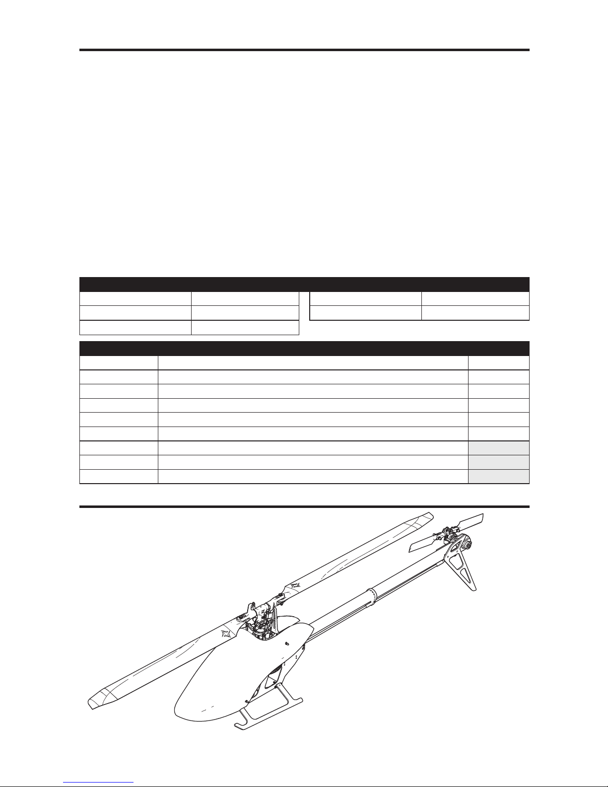
• Blade® Fusion™ 360 helicopter
Length 26.9 in (685mm)
Height 26.9 in (190mm)
Flying Weight 32.2 oz (915 g)
Main Rotor Diameter 31.3 in (796mm)
Tail Rotor Diameter 6.9 in (175mm)
To receive product updates, special offers and more, register your product at www.horizonhobby.com
Box Contents
Specifi cations
If you own this product, you may be
required to register with the FAA.
For up-to-date information on how to
register with the FAA, please visit
https://registermyuas.faa.gov/.
For additional assistance on regulations
and guidance on UAS usage,
visit knowbeforeyoufl y.org/
Page 4

4
EN
Low Voltage Cuto (LVC)
LED Indicator on Flight Controller
The ESC will continuously lower power to the motor until
complete shutdown when the battery reaches 12V under
load. This helps prevent over-discharge of the Li-Po battery.
Land immediately when the ESC activates LVC. Continuing
to fl y after LVC can damage the battery, cause a crash or
both. Crash damage and battery damaged due to overdischarge are not covered under warranty.
Repeatedly fl ying the helicopter until LVC activates will
damage the helicopter battery.
Disconnect and remove the Li-Po battery from the aircraft
after use to prevent trickle discharge. During storage, make
sure the battery charge does not fall below 3V per cell.
The included electronic speed controller (ESC) utilizes a
head speed governor to maintain a constant head speed
during fl ight. The governor will work to maintain a constant
head speed throughout maneuvers and the discharge cycle
of the fl ight battery.
The throttle position determines the requested head speed,
and although throttle curves are still used, they will be a
constant value; all positions of the curve are set to the same
value. The lowest position of the normal fl ight mode throttle
curve must be set to 0 to ensure the motor can be disabled.
The default throttle curve settings listed in the transmitter
setup tables should be acceptable to most pilots and
we recommend starting with these values. If you feel
an adjustment is necessary after a few fl ights, adjust
the throttle percentage for the desired fl ight mode. We
recommend making small changes of 5% to fi nd your
preferred head speed.
Remember the throttle position on the transmitter is simply
requesting a specifi c head speed and this is not related to
the actual motor power percentage.
Electronic Speed Controller Governor Operation
First Flight Preparation
• Remove and inspect contents
• Begin charging the fl ight battery (not included)
• Install the fl ight battery in the helicopter
(once it has been fully charged)
• Program your computer transmitter
• Bind your transmitter
• Familiarize yourself with the controls
• Find a suitable area for fl ying
Flying Checklist
❏ Always turn the transmitter on fi rst
❏ Plug the fl ight battery into the lead from the ESC
❏ Allow the ESC to initialize and arm properly
❏ Verify control directions and gyro compensations are correct
❏ Fly the model
❏ Land the model
❏ Unplug the fl ight battery from the ESC
❏ Always turn the transmitter off last
LED Indicator on FC Indicator Description
Red Solid
FC6250HX waiting for receiver connection, system will not initialize until connected
Yellow Flash Calibrating
Slow Green Flash Ready to Fly
Slow Red Flash
Failsafe Active
Red Solid and Yellow Flash
Calibration Error, FC not level or is being moved during calibration
Page 5

5
EN
Model Type
HELI
Swash Type
1 servo Normal
Timer
Mode Count Down
Time 3:00 Tone
Start Throttle Out
Over 25%
Channel Travel Reverse
All
Channels
100/100 Normal
Servo Setup
FUNCTION LIST
DX7s, DX8
Throttle Curve
Switch Pos (F Mode)
Pt 1 Pt 2 Pt 3 Pt 4 Pt 5DX7s DX8
NN045505050
16060606060
1 2 75 75 75 75 75
HOLD HOLD 0 0 0 0 0
Pitch Curve
Switch Pos (F Mode)
Pt 1 Pt 2 Pt 3 Pt 4 Pt 5
DX7s DX8
N N 30 40 50 75 100
1 0 25 50 75 100
1 2 0 25 50 75 100
HOLD HOLD 0 25 50 75 100
SYSTEM SETUP
F-Mode Setup
Flight Mode F Mode
Hold Hold
SW Select
Trainer AUX 2
F Mode Gear
Gyro INH
Mix INH
Hold INH
Knob INH
Frame Rate
11ms
DSMX
Gyro
Normal 75%
Stunt 1 75%
Hold 75%
Channel Gear
SW F Mode
D/R & Expo
Chan
Switch Pos
(Ail D/R)
D/R ExpoDX7s
DX8
AILE/
ELEV/
RUDD
0 0 100/100 0
1 85/85 0
1 2 85/85 0
Transmitter Setup
Program your transmitter before attempting to bind or fl y
the helicopter. Always start by creating a new model in the
transmitter to ensure no existing settings are inadvertently
used. Transmitter programming values are shown below for the
Spektrum™ transmitters. The fi les for models using Spektrum™
transmitters with Spektrum AirWare™ software are also
available for download online at www.spektrumrc.com.
D/R & Expo
Channel Sw Pos D/R Expo
AILE/ELEV/
RUDD
0 100 0
1850
Timer
Down Timer 4:00
Switch THR CUT
ADJUST LIST
SETUP LIST
DX6i
Throttle Curve
Switch Pos (F Mode) Pos 1 Pos 2 Pos 3 Pos 4 Pos 5
NORM 0 60 60 60 60
STUNT* 80 80 80 80 80
Mix 1
GYRO > GYRO ACT
RATE D+125% U+125%
SW ELE D/R TRIM-INH
TRAVEL ADJ
Channel Travel
All Channels 100/100
Reverse
Channel Direction
All Channels N
GYRO
RATE SW-F.MODE
Switch Pos (F Mode)
0 82% NORM 0
1 75% STUNT 1
Modulation Type
AUTO DSMX-ENABLE
D/R COMBI
D/R SW AILE
Model Type HELI
Swash Type 1 servo 90
Pitch Curve
Switch Pos (F Mode) Pos 1 Pos 2 Pos 3 Pos 4 Pos 5
NORM 25 37 50 75 100
STUNT 0 25 50 75 100
HOLD 25 37 50 75 100
Page 6
6
EN
* Function is not available on
all transmitters
Throttle Curve
Sw Pos
(B) Pt 1 Pt 2 Pt 3 Pt 4 Pt 5
N 0 60 60 60 60
16565656565
28080808080
Hold 0 0 0 0 0
Pitch Curve
Sw Pos
(B) Pt 1 Pt 2 Pt 3 Pt 4 Pt 5
N 25 37 50 75 100
1 0 25 50 75 100
2 0 25 50 75 100
HOLD 25 37 50 75 100
Channel Travel Reverse
THR 100/100 Normal
AIL 100/100 Normal
ELE 100/100 Normal
RUD 100/100 Normal
GER 100/100 Normal
Channel Travel Reverse
PIT 100/100 Normal
AX2* 100/100 Normal
AX3* 100/100 Normal
AX4* 100/100 Normal
Servo Setup
FUNCTION LIST
DX6G2, DX6e, DX7G2, DX8G2, DX8e, DX9, iX12, DX18, DX20
Timer
Mode Count Down
Time 5:00
Start Throttle Out
Over 5%
One Time Inhibit
Model Type HELI
Swash Type Normal
F-Mode Setup
Switch 1 Switch B
Switch 2 Inhibit
Hold Switch Switch H
0
1
Channel Assign
Channel Input Confi g
1 Throttle
2 Aileron
3 Elevator
4 Rudder
5 Gear INH
6 Collective
7 AUX 2*
Frame Rate
11ms*
DSMX
SYSTEM SETUP
Gyro
Normal 85%
Stunt 1 78%
Stunt 2 65%
Hold 85%
Channel Gear
Switch Flight Mode
Mixing
P-Mix 1 Normal
Channels Ger > Gyr
Rate 125%/0%
Offset –100%
Switch Switch I
Position 0 1
D/R & Expo
Chan Sw (F) Pos D/R Expo
AILE
0 100/100 0
1 85/85 0
2 85/85 0
ELEV
0 100/100 0
1 85/85 0
2 85/85 0
Rudd
0 100/100 0
1 85/85 0
2 85/85 0
Transmitter Setup
Page 7
7
EN
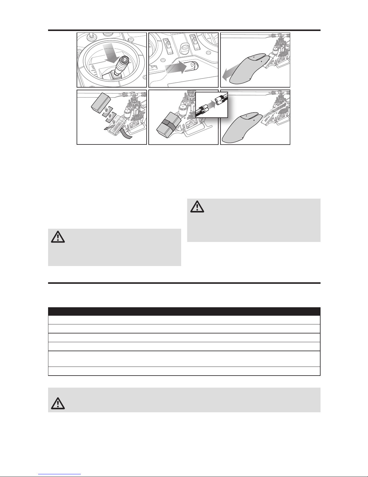
1. Lower the throttle.
2. Power on the transmitter.
3. Center all trims.
4. To allow the ESC to arm and to keep rotors from
initiating at startup, turn on throttle hold and normal
fl ight mode before connecting the fl ight battery.
5. Attach hook material to the helicopter frame and loop
material to the battery.
6. Install the fl ight battery on the helicopter frame. Secure
the fl ight battery with a hook and loop strap. Connect
the battery cable to the ESC.
CAUTION: Make sure the fl ight battery, wire and
connector does not come into contact with the
motor. Failure to do so will cause the motor, ESC and
battery to overheat, resulting in a crash causing property
damage and injury.
7. Do not move the helicopter until the fl ight controller
initializes. The swashplate will center, indicating that
the unit is ready. The fl ight controller status LED will
display a slow green fl ash once initialization has been
completed.
8. The helicopter motor will emit a series of tones,
indicating the ESC is armed.
CAUTION: Always disconnect the Li-Po battery
from the ESC power lead when not fl ying to avoid
over-discharging the battery. Batteries discharged below
the lowest approved voltage may become damaged,
resulting in loss of performance and potential fi re when
batteries are charged.
Binding Procedure
1. Program your transmitter using the Transmitter Setup found in this manual.
2. Insert the bind plug in the BIND port on the wiring harness between the fl ight controller and the receiver.
3. Connect the fl ight battery to the ESC. The orange LED on the receiver will begin fl ashing rapidly to indicate bind mode.
4. Move the throttle stick to the low throttle position in normal mode.
5. Follow the procedures of your specifi c transmitter to enter bind mode. The system will connect within a few seconds.
Once connected, the orange LED on the receiver will come on solid orange.
6. Disconnect the fl ight battery and remove the bind plug. Store the bind plug in a convenient place.
Transmitter and Receiver Binding
Binding is the process of programming the receiver to recognize the GUID (Globally Unique Identifi er) code of a single
specifi c transmitter. You need to ‘bind’ your chosen Spektrum™ DSM2®/DSMX® technology equipped aircraft transmitter
to the receiver for proper operation.
NOTICE: Remove the bind plug to prevent the system from entering bind mode the next time the power is turned on.
CAUTION: When using a Futaba® transmitter with a Spektrum™ DSM2® module, you must reverse the throttle channel.
If you encounter problems, obey binding instructions and refer to transmitter troubleshooting guide for other instructions.
If needed, contact the appropriate Horizon Product Support offi ce.
Installing the Flight Battery
Page 8

8
EN
Throttle Hold
Control Tests
Throttle hold is used to prevent the motor from powering on
inadvertently. For safety, turn throttle hold ON any time you
need to touch the helicopter or check the direction controls.
Throttle hold is also used to turn off the motor quickly if the
helicopter is out of control, in danger of crashing, or both.
The blades will continue to spin briefl y when throttle hold is
activated. Pitch and direction control is still maintained.
CAUTION: You must complete the Tail Rotor and Cyclic tests prior to every fl ight. Failure to complete the tests
and ensuring the sensor corrects in the proper direction can cause the helicopter to crash, resulting in property
damage and injury.
Tail Rotor
1. Power on the transmitter.
2. Turn TH HOLD ON and put transmitter in normal mode.
3. Connect the fl ight battery to the ESC.
4. Once Initialization is complete the LED on the
FC6250HX will begin fl ashing green.
5. Move the rudder stick
to the right. The pitch
slider on the tail shaft
should move toward
the tail case. If the
pitch slider moves in
the opposite direction,
ensure the rudder
channel reverse
setting within the transmitter is set to normal.
6. Release the rudder control. Manually turn the helicopter
nose to the left. The fl ight controller should compensate
by moving the tail slider towards the tail case.
Cyclic and Collective Control Test
Ensure the throttle hold is ON when performing the direction control tests. Test the controls prior to each fl ight to
ensure the servos, linkages and parts operate correctly. If the controls do not react as shown in the illustrations below,
confi rm the transmitter is programmed correctly before continuing on to the Motor test.
Elevator
Aileron
Rear View
Left Side View Left Side View
Rear View
Elevator down Elevator up
Aileron left Aileron right
Cyclic
When using a fl ybarless fl ight controller, you are controlling rotational rates while the
SPMAR6250HX
controls the
servos. You are not directly controlling the servos with the
transmitter.
It is normal for the swashplate to slowly move back to
its original position after a stick input and for the servos
to not move at the same speed as your control sticks.
1. Tilt the helicopter forward. The swashplate must tilt
backward.
2. Roll the helicopter left. The swashplate must roll right.
Page 9

9
EN
Motor Test
Place the helicopter outdoors on a clean, fl at and level
surface (concrete or asphalt) free of obstructions. Always
stay clear of moving rotor blades.
1. Before you continue, confi rm that TH HOLD is ON. The
motor will emit a series of tones after the helicopter’s
ESC has armed properly.
WARNING: The motor will spin when the throttle is
increased while TH HOLD is OFF.
WARNING: Stay at least 30 feet (10 meters) away
from the helicopter when the motor is running. Do
not attempt to fl y the helicopter at this time.
2. Ensure the throttle is lowered completely. Confi rm
the transmitter is still set to normal fl ight mode. Turn
throttle hold OFF to enable throttle control. Slowly
increase the throttle until the blades begin to spin. The
main blades spin clockwise when viewing the helicopter
from the top. The tail rotor blades spin counterclockwise
when viewing the helicopter from the right-hand side.
Collective Pitch
Front View Front View
Collective pitch up Collective pitch down
Pre-Flight Checklist
❏ Check all screws and ensure that they are tight
❏ Check belt tension and ensure that it is not too tight or
too loose
❏ Check main and tail blades to ensure they are not damaged
❏ Check all links and make sure they move freely but do
not pop off easily
❏ Check that the transmitter and fl ight batteries are fully
charged
❏ Check all wires to ensure that they are not cut, pinched,
or chaffed and are properly secured
❏ Check all wire connections
❏ Check gears and make sure no teeth are missing
❏ Make sure fl ight battery is properly secured
❏ Make sure the receiver is properly secured
❏ Perform a complete control test
❏ Verify the fl ight controller is correcting in the proper directions
❏ Check that servos are functioning properly
Consult local laws and ordinances before choosing a location to fl y your aircraft.
Select a large, open area away from people and objects.
Your fi rst fl ights should be outdoors in low-wind conditions.
Always stay at least 30 feet (10 meters) away from the
helicopter when it is fl ying.
The Blade Fusion 360 is intended to be fl own outdoors by
experienced pilots.
Takeoff
Deliberately increase throttle and establish a hover
at least 24” (0.6 meter) high, outside of ground effect.
CAUTION: Making large inputs to the roll or pitch
controls while the helicopter is on the ground
may result in a crash.
Flying
The helicopter lifts off the ground when the rotor head
reaches a suitable speed. Establish a low-level hover to
verify proper operation of your helicopter.
First fl ights should be performed in normal mode and low
cyclic and rudder dual rates until you are familiar with the
fl ying manner of the Blade Fusion 360.
CAUTION: Always fl y the helicopter with your back to
the sun and the wind to prevent loss of fl ight control.
Landing
Establish a low level hover. Deliberately lower the throttle
until the helicopter lands.
When the helicopter is in stunt mode:
• The rotor head speed is constant.
• The main rotor will increase negative pitch as the
throttle/collective stick is moved from the middle stick
position to the low stick position. Negative pitch allows
the helicopter to fl y upside down and perform aerobatics.
Change between stunt and idle up modes in a hover with
the throttle near the hovering stick position.
WARNING: Do not use wooden main blades with
the Blade Fusion 360. Injury and/or property
damage could occur. Only use Blade Fusion 360
replacement carbon fi ber main blades.
Flying the Blade Fusion 360
Page 10

10
EN
Gyro Gain Adjustment
• If the tail wags or oscillates, lower the gain on the gyro.
In the transmitter gyro menu, decrease the gyro gain
values a small amount at a time until the helicopter is
stable within a particular fl ight mode.
• If the tail is drifting while hovering, increase the gain on the gyro.
In the transmitter gyro menu, increase the gyro gain
values a small amount at a time until the tail starts to
wag/oscillate. Afterwards, reduce the gain until the tail
stops wagging/oscillating within a particular fl ight mode.
Tail Belt Tension
Belt tension that is too tight results in loss of power and causes the belt to wear more quickly. Tension that is too loose
can cause belt damage and loss of tail rotor control in fl ight.
To check for proper belt tension:
1. View the tail rotor drive belt through the opening at the
back of the main frame.
2. Use a hex wrench or standard screwdriver to compress the
belt through the opening.
3. Apply light pressure on the belt, compressing the belt
toward the left side of the tail boom.
4. The belt tension is correct if the compressed side of
the belt reaches approximately halfway to the opposite
side of the belt.
a. If the compressed side of the belt reaches farther
than halfway to the other side of the belt, the tension
is too loose.
b. If the compressed side of the belt does not reach half-
way to the other side of the belt, the tension is too tight.
To adjust belt tension:
1. Loosen the two screws at the back of the main frame.
2. Slide the boom forward or aft to adjust the belt tension.
3. When the belt tension is properly adjusted, tighten the
two screws at the back of the frame.
Post-Flight Inspections and Maintenance
Ball Links
Make sure the plastic ball link holds the control ball, but is not tight (binding) on the ball. When a link
is too loose on the ball, it can separate from the ball during fl ight and cause a crash. Replace worn
ball links before they fail.
Cleaning
Make sure the battery is not connected before cleaning. Remove dust and debris with a soft brush
or a dry lint free cloth.
Bearings Replace bearings when they become damaged.
Wiring Make sure wiring does not block moving parts. Replace damaged wiring and loose connectors.
Fasteners
Make sure there are no loose screws, other fasteners or connectors. Do not over tighten metal screws
in plastic parts. Tighten screw so parts are mated together, then turn screw only 1/8th of a turn more.
Rotors
Make sure there is no damage to rotor blades and other parts which move at high speed. Damage
to these parts includes cracks, burrs, chips or scratches. Replace damaged parts before fl ying.
Flight Controller
Make sure the fl ight controller is securely attached to the frame. Replace the double-sided tape
when necessary. The helicopter will crash if the fl ight controller separates from the helicopter frame.
Page 11

11
EN
The Fusion 360 BNF fl ight controller may be programmed from any compatible Spektrum transmitter
(visit SpektrumRC.com for more information).
The fl ight controller shipped with BNF models has a range of adjustable parameters suitable for the Fusion 360 Helicopter
and is not intended for use in other aircraft.
It is important to use the included servos with the BNF fl ight controller because the adjustable parameters available for
the SPMAR6250HX are designed around the recommended servos. It is possible there may not be enough range for the
helicopter to be tuned when using alternative servos.
Entering the Advanced Parameters Men
u
With the helicopter bound to the transmitter and powered on, enter the Function List and select Forward Programming.
The list of adjustable parameters and the range of values available for tuning have been tailored for this helicopter. Make
small changes to one parameter at a time and test fl y the changes before changing the parameter further or changing a
different parameter.
Calibration Procedure:
If the helicopter is experiencing drift issues, perform the following calibration. The calibration procedure may also be
needed following crash repairs.
1. Ensure the surface used for calibration is level.
2. Power on the transmitter and activate throttle hold.
3. Connect the fl ight batter to the ESC and allowing the
model to initialize.
4. Turn Throttle Hold ON.
5. Using a bubble level as shown below, level the
helicopter by placing a shim under the landing skid.
6. Enter the Function List on your transmitter.
7. Select Forward Programming.
8. Select System Setup.
9. Select Calibration.
10. Select Apply and the calibration will begin. The
LED will fl ash yellow indicating the calibration is
proceeding normally. If the LED changes to red this
indicates the model is not near level or the model was
moved, in this case the calibration starts over.
11. After the calibration is successfully completed, the
receiver LED will will change to a slow green fl ash
which indicates the calibration has completed.
12. Proceed to the pre-fl ight check list procedure before
fl ying your model.
Applies to forward programming capable Spektrum Transmitters including
DX6G2, DX7G2, DX8G2, DX9, iX12, DX18, DX20
Factory Reset
If the process of tuning the Fusion 360 helicopter results in undesirable fl ight performance, you can reset the settings
back to factory defaults by selecting the Factory Reset option in Forward Programming.
1. Enter the Function List
2. Select Forward Programming
3. Select System Setup
4. Select Factory Reset
5. Select Apply
6. Perform the Setup->Swashplate->Sub Trim function
and ensure the servos are properly trimmed.
7. Proceed with the pre-fl ight check list procedure
before fl ying the model.
The Fusion 360 default settings are appropriate for most users. We recommend fl ying with the default parameters before
making any adjustments.
Advanced Tuning (Forward Programming)
Bubble level
Shim
Page 12

12
EN
Control Input in Servo
Adjustment Mode
Action in Servo
Adjustment Mode
Fore/Aft Cyclic
Select Previous or Next Servo
Right/Left Cyclic
Increase or Decrease Sub
Trim Adjustment
Right Tailrotor
Hold For Two Seconds;
Neutral Position is Reset
on Selected Servo
Left Tailrotor and Low
throttle
Hold for Four Seconds; Exit
Servo Adjustment mode
The advanced tuning options must be entered within 30 seconds after initialization completes. In addition the combination of dual rates and travel adjustments must result in a throw greater than 65% in order to enter the tuning modes.
Entering Servo Adjustment Mode
1. Lower the throttle stick to the lowest position.
2. Power ON the transmitter and activate throttle hold.
3. Install the fl ight battery on the helicopter frame,
securing it with the hook and loop strap.
4. Connect the battery connector to the ESC.
5. After initialization is complete (indicated by a slow
green fl ash), hold the left stick to the bottom left corner
and the right stick to the bottom right corner as shown.
6. Servo Adjustment Mode is indicated by the swashplate
servos jumping and then slowly moving back to center.
7. Release the sticks and proceed to the next step.
Adjusting the Servo Neutral Position
With the model in Servo Adjustment Mode, the control stick
and gyro inputs are disabled and the servos are held in the
neutral position. Check the position of the servo arms to
verify they are perpendicular to the servos.
• If the arms are perpendicular to the servos, no adjustment is necessary.
Exit Servo Adjustment Mode.
• If one or more servo arm is not perpendicular to the
servos, continue the servo adjustment process.
While watching the swashplate servos, apply fore or aft
cyclic and release. One of the servos will jump, indicating
the selected servo. Apply fore or aft cyclic and release until
the servo that needs to be adjusted is selected.
Once the servo you wish to adjust is selected, move the
cyclic stick left or right to adjust the servo neutral position
in the desired direction.
To reset the current servo to the default neutral position, hold
the rudder stick full right for two seconds.
The range of adjustment is limited. If you are unable to
adjust the servo arm to be perpendicular to the servo, you
must reset the servo to the default neutral position, remove
the servo arm and place it back onto the servo as close to
perpendicular as possible. You may then adjust the servo
neutral position using left or right cyclic stick.
Swashplate Leveling
Before saving your adjustments and exiting servo
adjustment mode, verify the swashplate is level and both
main rotor blades are at 0 degrees pitch.
If they are not, make linkage adjustments as necessary.
Saving the Servo Adjustments
1. Lower the throttle stick to the lowest position and
release the sticks.
2. Move the tail rotor stick to the left and hold for four
seconds to exit Servo Adjustment Mode. The servos will
jump indicating a return to normal operation.
3. Release the tail rotor stick.
4. Perform the pre-fl ight checklist procedure before fl ying
your model.
Advanced Tuning (Non-Forward Programming)
Applies to Spektrum transmitters not capable of forward programing including
DX6i, DX6e, DX7s DX8, and DX8e
Your Blade Fusion 360 was setup at the factory and test
fl own. The servo adjustment steps are usually only necessary in special circumstances, such as after a crash or if a
servo or linkage is replaced.
For pilots fl ying with a transmitter not capable of forward
programming use the following procedures to make servo
adjustments and perform the calibration procedure.
Page 13

13
EN
LED Indicator on FC Indicator Description
Red Solid
FC6250HX waiting for receiver
connection, system will not
initialize until connected
Yellow Flash Calibrating
Slow Green Flash Ready to Fly
Red and Yellow Flash
Failsafe Active
If the helicopter is experiencing drift issues after completing the trim fl ight procedure, perform the following calibration.
The calibration procedure may also be needed following crash repairs.
To perform the calibration procedure:
1. Ensure the surface used for calibration is level.
2. Power on the transmitter and helicopter, allowing
them to initialize.
3. Turn Throttle Hold ON.
4. Ensure the main motor is disconnected.
5. Using a bubble level as shown below, level the
helicopter by placing a shim under the landing skid.
6. Hold the left stick to the bottom right corner, and the
right stick to the upper left corner.
7. The LED on the Flight Controller will fl ash yellow
while caibrating
Do not move the helicopter until the calibration
is completed. If the LED displays a red LED an error
has occurred. Begin the calibration procedure again,
starting with step 1.
8. After the calibration is successfully completed, the
receiver LED will blink green.
Bubble level
Shim
Calibration Procedure
Page 14

14
EN
Troubleshooting Guide
Problem Possible Cause Solution
Helicopter will not bind
to the transmitter
(during binding)
Low ight battery or transmitter
battery voltage
Fully charge or replace the ight battery and/or transmitter
batteries
Transmitter is not in bind mode
Power on the transmitter while holding the Trainer/Bind
switch. Hold the Trainer/Bind switch until binding is complete
Transmitter too close to the
helicopter during binding process
Power off the transmitter. Move the transmitter further away
from the helicopter.
Disconnect and reconnect the ight battery to the helicopter
and follow binding instructions
Helicopter will not link
to the transmitter
(after binding)
Helicopter is bound to a
different model memory
(ModelMatch™radios only)
Disconnect the ight battery. Select the correct model
memory on the transmitter. Reconnect the ight battery
Flight battery/Transmitter battery
charge is too low
Replace or recharge batteries
Flight controller will not
initialize
The helicopter was moved during
initialization
Lay the helicopter on its side during initialization if windy
The transmitter is powered off Power on the transmitter
Controls are not centered
Center elevator, aileron and rudder controls. Make sure the
throttle is at idle
Helicopter will not respond
to the throttle but responds
to other controls
Throttle not at idle and/or throttle
trim is too high
Lower the throttle stick and lower the throttle trim
The transmitter is not in normal
mode or throttle hold is on
Make sure the transmitter is in normal mode and throttle hold
is off
The motor is not connected to the
ESC or the motor wires are damaged
Connect the motor wires to the ESC and check motor wires
for damage
Flight battery charge is too low Replace or recharge ight battery
Throttle channel is reversed Reverse the throttle channel on the transmitter
Helicopter power is lacking
Flight battery has low voltage Fully charge the ight battery
Flight battery is old or damaged Replace the ight battery
Flight battery cells are unbalanced
Fully charge the ight battery, allowing the charger time to
balance the cells
Excessive current is being drawn
through the BEC
Check all servos and the helicopter motor for damage
Tail drive belt tension is not correct See "Tail Belt Tension" section in this manual
Helicopter will not lift off
Main rotor head is not spinning in
the correct direction
Make sure the main rotor head is spinning clockwise. Refer to
the motor control test
Transmitter settings are not correct Check throttle and pitch curve settings and pitch control direction
Flight battery has low voltage Fully charge the ight battery
Main rotor blades are installed
backwards
Install the main rotor blades with the thicker side as the
leading edge
The helicopter tail
spins out of control
Rudder control and/or sensor
direction reversed
Make sure the rudder control and the rudder sensor are
operating in the correct direction
Tail servo is damaged Check the rudder servo for damage and replace if necessary
Inadequate control arm throw
Check the rudder control arm for adequate travel and adjust
if necessary
Tail belt is too loose Make sure the tail drive belt tension is adjusted correctly
The helicopter wobbles
in ight
Cyclic gain is too high
Tuning options using forward programming are available
under the “Advanced Settings” section in this manual
Headspeed is too low
Increase the helicopter's head speed via your transmitter
settings and/or using a freshly charged ight pack
Dampers are worn Replace the main rotor head dampers
Page 15

15
EN
Exploded View
33
41
34
34
37
33
9
9
44
28
33
16
43
31
29
3
1
5
32
32
18
39
42
30
17
17
7
36
35
Page 16

16
EN
26
26
27
38
23
24
21
24
35
8
22
22
20
25
19
2
9
13
4
14
11
6
4
11
6
12
15
10
Page 17

17
EN
# Part # Description
1 BLH1603
One-Way bearing Hub with One-Way Bearing
2 BLH1620
3x8x3.5 Thrust Bearing (2)
3 BLH1649
One-Way Bearing Shaft and Shim Set
4 BLH4705 Spindle Set (2): 360 CFX
5 BLH4710 Belt Drive Puller: 360 CFX
6 BLH4720 Linkage Set: 360 CFX
7 BLH4721 Anti-Rotation Bracket: 360 CFX
8 BLH4728 Tail Drive Belt: 360 CFX
9 BLH4831 Servo Arm, Linkage Balls, Tail Servo Mount
10 BLH5201 Fusion 350mm Main Blade
11 BLH5202 Main Grip Set (2): Fusion 360
12 BLH5203 Washout Mixing Arms: Fusion 360
13 BLH5204 Main Rotor Headblock: Fusion 36
14 BLH5205 Damper Set (2) 90 : Fusion 360
15 BLH5206 Swashplate: Fusion 360
16 BLH5207 Motor Mount: Fusion 360
17 BLH5208 Body Post Mounts (4): Fusion 36
18 BLH5209 Fusion 360 Painted Canopy
19 BLH5210 Main Shaft: Fusion 360
20 BLH5211 Fusion 65mm Tail Blade Set
21 BLH5212 Alu Tail Grip Set: Fusion 360
22 BLH5213 Tail Rotor Hub: Fusion 360
# Part # Description
23 BLH5214 Tail Pitch Slider: Fusion 360
24 BLH5215 Rear Tail Case: Fusion 360
25 BLH5216 Vertical Tail Fin: Fusion 360
26 BLH5217 Tail Rotor Pushro: Fusion 360
27 BLH5218 Tail Boom Set (2): Fusion 360
28 BLH5219 Tail Boom Clamp (2): Fusion 360
29 BLH5220 Tail Belt Guide: Fusion 360
30 BLH5221 Frame (1): Fusion 360
31 BLH5222 Gear Mount (2): Fusion 360
32 BLH5223 Landing Gear: Fusion 360
33 BLH5224 Carbon Plates: Fusion 360
34 BLH5225 Bear Block Set (3): Fusion 360
35 BLH5226 Tail Rotor Bellcrank: Fusion 360
36 BLH5232 Helical Pinion 12T
37 BLH5337 Helical Main Gear Black
38 BLH5336 Tail Shaft with Pulley
39 BLHHW60A Blade Heli 60 A Brushless ESC
40 SPM4649T DSMX Quad Race Receiver w/telemetry
41 SPMFC6250HX Flight Controller
42 BLH4731 Brushless Out-Runner Motor, 1800Kv
43 SPMSH3055 H3055 M-T / U-S Micro Cyclic Servo
44 SPMSH3065 H3065 M-T / U-S Micro Tail Servo
Part # Description
BLH5051 Brushless Motor, 3400Kv: 360 CF
BLH5230 10T Helical Pinion
BLH5231 11T Helical Pinion
SPMX18006S50 1800mAh 6S 22.2V 50C LiPo IC3
Part # Description
SPMSP1040 Gear Set: H3050
SPMSP1041 Gear Set: H3060
SPMSP2052 Case Set: H3050, H3060
Description Bearing Size
Main Grip Radial Bearings
9mm x 5mm x 3mm
Main Thrust Bearings
9mm x 4mm x 4mm
Washout Arm Pivot Bearings
5mm x 2mm x 2.5mm
Washout Arm Link Bearing 4mm x 1.5mm x 2mm
Main Shaft Bearing Blocks 12mm x 6mm x 4mm
Tail Belt Front Idler Pulley 5mm x 2mm x 2.5mm
Description Bearing Size
Tail Belt Rear Idler Pulley 7mm x 4mm x 2.5mm
Tail Case Tail Shaft Bearings F10mm x 4mm x 4mm
Tail Bellcrank Bearings 6mm x 3mm x 2.5mm
Tail Pitch Slider Bearings 8mm x 5mm x 2.5mm
Tail Grip Radial Bearings 6mm x 3mm x 5mm
Tail Grip Thrust Bearings 6mm x 2.5mm x 3mm
Part # Description
SPMX18006S50 6S LiPo Battery, 1800mAh, 50C, iC3
SPMXC1000
Smart S1200 DC Charger, 1x200W
Part # Description
SPMXC1010
Smart S2100 AC Charger, 2x100W
SPMXC10201 Smart 30-Amp Power Supply
Ball Bearing Sizes
Parts List
Optional Parts List
Recommended Parts List
Page 18

18
EN
Limited Warranty
What this Warranty Covers
Horizon Hobby, LLC, (Horizon) warrants to the original purchaser
that the product purchased (the “Product”) will be free from
defects in materials and workmanship at the date of purchase.
What is Not Covered
This warranty is not transferable and does not cover (i) cosmetic
damage, (ii) damage due to acts of God, accident, misuse, abuse,
negligence, commercial use, or due to improper use, installation,
operation or maintenance, (iii) modi cation of or to any part of the
Product, (iv) attempted service by anyone other than a Horizon
Hobby authorized service center, (v) Product not purchased from
an authorized Horizon dealer, (vi) Product not compliant with
applicable technical regulations, or (vii) use that violates any
applicable laws, rules, or regulations.
OTHER THAN THE EXPRESS WARRANTY ABOVE, HORIZON
MAKES NO OTHER WARRANTY OR REPRESENTATION, AND
HEREBY DISCLAIMS ANY AND ALL IMPLIED WARRANTIES,
INCLUDING, WITHOUT LIMITATION, THE IMPLIED WARRANTIES
OF NON-INFRINGEMENT, MERCHANTABILITY AND FITNESS FOR
A PARTICULAR PURPOSE. THE PURCHASER ACKNOWLEDGES
THAT THEY ALONE HAVE DETERMINED THAT THE PRODUCT WILL
SUITABLY MEET THE REQUIREMENTS OF THE PURCHASER’S
INTENDED USE.
Purchaser’s Remedy
Horizon’s sole obligation and purchaser’s sole and exclusive
remedy shall be that Horizon will, at its option, either (i) service,
or (ii) replace, any Product determined by Horizon to be defective.
Horizon reserves the right to inspect any and all Product(s)
involved in a warranty claim. Service or replacement decisions
are at the sole discretion of Horizon. Proof of purchase is
required for all warranty claims. SERVICE OR REPLACEMENT AS
PROVIDED UNDER THIS WARRANTY IS THE PURCHASER’S SOLE
AND EXCLUSIVE REMEDY.
Limitation of Liability
HORIZON SHALL NOT BE LIABLE FOR SPECIAL, INDIRECT,
INCIDENTAL OR CONSEQUENTIAL DAMAGES, LOSS OF
PROFITS OR PRODUCTION OR COMMERCIAL LOSS IN ANY WAY,
REGARDLESS OF WHETHER SUCH CLAIM IS BASED IN CONTRACT,
WARRANTY, TORT, NEGLIGENCE, STRICT LIABILITY OR ANY OTHER
THEORY OF LIABILITY, EVEN IF HORIZON HAS BEEN ADVISED OF
THE POSSIBILITY OF SUCH DAMAGES. Further, in no event shall
the liability of Horizon exceed the individual price of the Product
on which liability is asserted. As Horizon has no control over use,
setup, nal assembly, modi cation or misuse, no liability shall
be assumed nor accepted for any resulting damage or injury. By
the act of use, setup or assembly, the user accepts all resulting
liability. If you as the purchaser or user are not prepared to accept
the liability associated with the use of the Product, purchaser is
advised to return the Product immediately in new and unused
condition to the place of purchase.
Law
These terms are governed by Illinois law (without regard to
con ict of law principals). This warranty gives you speci c legal
rights, and you may also have other rights which vary from state
to state. Horizon reserves the right to change or modify this
warranty at any time without notice.
WARRANTY SERVICES
Questions, Assistance, and Services
Your local hobby store and/or place of purchase cannot provide
warranty support or service. Once assembly, setup or use of the
Product has been started, you must contact your local distributor
or Horizon directly. This will enable Horizon to better answer your
questions and service you in the event that you may need any
assistance. For questions or assistance, please visit our website
at www.horizonhobby.com, submit a Product Support Inquiry, or
call the toll free telephone number referenced in the Warranty
and Service Contact Information section to speak with a Product
Support representative.
Inspection or Services
If this Product needs to be inspected or serviced and is compliant in the
country you live and use the Product in, please use the Horizon Online
Service Request submission process found on our website or call
Horizon to obtain a Return Merchandise Authorization (RMA) number.
Pack the Product securely using a shipping carton. Please note that
original boxes may be included, but are not designed to withstand
the rigors of shipping without additional protection. Ship via a carrier
that provides tracking and insurance for lost or damaged parcels,
as Horizon is not responsible for merchandise until it arrives and is
accepted at our facility. An Online Service Request is available at http://
www.horizonhobby.com/content/service-center_render-service-center.
If you do not have internet access, please contact Horizon Product
Support to obtain a RMA number along with instructions for submitting
your product for service. When calling Horizon, you will be asked to
provide your complete name, street address, email address and phone
number where you can be reached during business hours. When
sending product into Horizon, please include your RMA number, a list of
the included items, and a brief summary of the problem. A copy of your
original sales receipt must be included for warranty consideration. Be
sure your name, address, and RMA number are clearly written on the
outside of the shipping carton.
NOTICE: Do not ship LiPo batteries to Horizon. If you
have any issue with a LiPo battery, please contact the
appropriate Horizon Product Support offi ce.
Warranty Requirements
For Warranty consideration, you must include your
original sales receipt verifying the proof-of-purchase
date. Provided warranty conditions have been met, your
Product will be serviced or replaced free of charge. Service or
replacement decisions are at the sole discretion of Horizon.
Non-Warranty Service
Should your service not be covered by warranty, service will be
completed and payment will be required without noti cation
or estimate of the expense unless the expense exceeds 50%
of the retail purchase cost. By submitting the item for service
you are agreeing to payment of the service without noti cation.
Service estimates are available upon request. You must include
this request with your item submitted for service. Non-warranty
service estimates will be billed a minimum of ½ hour of labor.
In addition you will be billed for return freight. Horizon accepts
money orders and cashier’s checks, as well as Visa, MasterCard,
American Express, and Discover cards. By submitting any item
to Horizon for service, you are agreeing to Horizon’s Terms and
Conditions found on our website http://www.horizonhobby.com/
content/service-center_render-service-center.
ATTENTION: Horizon service is limited to Product
compliant in the country of use and ownership. If
received, a non-compliant Product will not be serviced.
Further, the sender will be responsible for arranging
return shipment of the un-serviced Product, through
a carrier of the sender’s choice and at the sender’s
expense. Horizon will hold non-compliant Product for a
period of 60 days from notifi cation, after which it will
be discarded.
10/15
Page 19

19
EN
Warranty and Service Contact Information
Country of
Purchase
Horizon Hobby Contact Information Address
United States
of America
Horizon Service Center
(Repairs and Repair Requests)
servicecenter.horizonhobby.com/RequestForm/
2904 Research Rd
Champaign, Illinois, 61822 USA
Horizon Product Support
(Product Technical Assistance)
productsupport@horizonhobby.com
877-504-0233
Sales
websales@horizonhobby.com
800-338-4639
European
Union
Horizon Technischer Service service@horizonhobby.eu
Hanskampring 9
D 22885 Barsbüttel, Germany
Sales: Horizon Hobby GmbH +49 (0) 4121 2655 100
FCC ID: BRWAR4649T
Contains IC: 6157A-AR4649T
FCC Information
This device complies with part 15 of the FCC rules.
Operation is subject to the following two conditions:
(1) This device may not cause harmful interference,
and (2) this device must accept any interference
received,
including interference that may cause undesired
operation.
CAUTION: Changes or modifi cations not
expressly approved by the party responsible
for compliance could void the user’s authority to
operate the equipment.
This product contains a radio transmitter with
wireless technology which has been tested
and found to be compliant with the applicable
regulations governing a radio transmitter in the
2.400GHz to 2.4835GHz frequency range.
Supplier’s Declaration of Conformity
Fusion 360 – BLH5250
This device complies with part 15 of the FCC
Rules. Operation is subject to the following
two conditions: (1) This device may not cause
harmful interference, and (2) this device must
accept any interference received, including
interference that may cause undesired operation.
CAUTION: changes or modifi cations not
expressly approved by the party responsible
for compliance could void the user’s authority to
operate the equipment.
NOTE: This equipment has been tested and found to
comply with the limits for a Class B digital device,
pursuant to part 15 of the FCC Rules. These limits
are designed to provide reasonable protection
against harmful interference in a residential
installation. This equipment generates, uses and can
radiate radio frequency energy and, if not installed
and used in accordance with the instructions, may
cause harmful interference to radio communications.
However, there is no guarantee that interference
will not occur in a particular installation. If this
equipment does cause harmful interference to radio
or television reception, which can be determined
by turning the equipment off and on, the user is
encouraged to try to correct the interference by one
or more of the following measures:
• Reorient or relocate the receiving antenna.
• Increase the separation between the equipment
and receiver.
• Connect the equipment into an outlet on a circuit
different from that to which the receiver is
connected.
• Consult the dealer or an experienced radio/TV
technician for help.
Horizon Hobby, LLC
2904 Research Rd.,
Champaign, IL 61822
Email: compliance@horizonhobby.com
Web: HorizonHobby.com
FCC Information
Page 20

20
EN
Compliance Information for the European Union
Instructions for disposal of WEEE by users in the European Union
This product must not be disposed of with
other waste. Instead, it is the user’s responsibility to dispose of their waste equipment by handing it over to a designated
collections point for the recycling of waste
electrical and electronic equipment. The
separate collection and recycling of your
waste equipment at the time of disposal will help to conserve natural resources and make sure that it is recycled in
a manner that protects human health and the environment.
For more information about where you can drop off your
waste equipment for recycling, please contact your local
city offi ce, your household waste disposal service or where
you purchased the product.
EU Compliance Statement: BLH5250
Horizon Hobby, LLC hereby declares that this
product is in compliance with the essential
requirements and other relevant provisions of the RED and
EMC Directives.
A copy of the EU Declaration of Conformity is available
online at: http://www.horizonhobby.com/content/supportrender-compliance.
IC Information
IC: 6157A-AR4649T
This device complies with Industry Canada licence-exempt
RSS standard(s). Operation is subject to the following two
conditions: (1) this device may not cause interference, and
(2) this device must accept any interference, including
interference that may cause undesired operation of the
device.”
Page 21

©2019 Horizon Hobby, LLC.
Blade, the Blade logo, Fusion, DSM, DSM2, DSMX, Bind-N-Fly, IC3, EC3, AirWare, SAFE, BNF, the BNF logo,
ModelMatch and the Horizon Hobby logo are trademarks or registered trademarks of Horizon Hobby, LLC.
The Spektrum trademark is used with permission of Bachmann Industries, Inc.
Futaba is a registered trademark of Futaba Denshi Kogyo Kabushiki Kaisha Corporation of Japan.
All other trademarks, service marks or logos are property of their respective owners. US D774,933.
Created 03/19 BLH5250 58420
 Loading...