

Page 1

Specifications
Length . . . . . . . . . . . . . . . . . . . . . . . 15.75 in (400mm)
Height . . . . . . . . . . . . . . . . . . . . . . . 7.17 in (182mm)
Main Rotor Diameter
Weight RTF w/Battery
Main Motor . . . . . . . . . . . . . . . . . . . . 180 (2 installed)
Battery . . . . . . . . . . . . . . . . . . . . . . .7.4V 800mAh Li-Po (included)
Transmitter . . . . . . . . . . . . . . . . . . . .FM 4-Channel (included)
On-Board Electronics . . . . . . . . . . . . . 4-in-1 Receiver/Mixer/ESC/Gyro (installed)
Servo . . . . . . . . . . . . . . . . . . . . . . . . EFLRS75 High-Speed, High-Torque (2 installed)
. . . . . . . . . . . . . 13.60 in (345mm)
. . . . . . . . . . . . 8.0 oz (227 g)
Page 2

Introduction
The Blade™ CX is a truly Ready-for-Anyone-to-Fly micro class electric helicopter. Coaxial counter-rotating blades
cancel out the rotational torque that makes hovering a conventional helicopter so difficult while providing
unsurpassed stability in all other phases of flight too. Whether you are a first-time helicopter pilot or an
experienced pilot looking for the best in coaxial micro helicopter performance, you’ll enjoy many of the outstanding
features that have the Blade CX flying in no time such as pre-installed main motors, 4-in-1 control unit with
receiver, mixer, ESC and gyro, and high-speed, high-torque S75 sub-micro servos. With the included 4-channel FM
transmitter, 2-cell 800mAh Li-Po battery pack and DC charger, you’ll have precise control for hovering, forward
flight and more with durations of up to 15 minutes per charge.
While the Blade CX is nearly ready-to-fly right from the box, please take the time to read through this manual
completely for tips on battery safety and charging, control checks, flying and more. Please also take a few
minutes to watch the included Instructional Video CD for additional tips and to see the Blade CX in action.
Table of Contents
Specifications ............................................................................................................................................ 1
Introduction ................................................................................................................................................
Warning .....................................................................................................................................................
Additional Required Equipment ....................................................................................................................
Blade CX RTF Contents ...............................................................................................................................
Warranty Information ...................................................................................................................................
Battery Warnings, Guidelines and Charging ...................................................................................................
Charge Errors and Indications .....................................................................................................................
Install the Transmitter Batteries ...................................................................................................................
Installing the Flight Battery ........................................................................................................................
Center of Gravity ......................................................................................................................................
Control Test .............................................................................................................................................
4-in-1 Control Unit Description, Arming and Motor Control Test ....................................................................
Before the First Flight ...............................................................................................................................
Flying the Blade
Main Motor Proportional Mix Trimmer Pot Description and Adjustment .........................................................
Upper Main Rotor Blade Tracking Adjustment .............................................................................................
Main Motor Care and Installing the Optional Main Motor Heat Sink ...............................................................
2005 Official AMA National Model Aircraft Safety Code ...............................................................................
Replacement Parts List .............................................................................................................................
Optional Parts List ....................................................................................................................................
Replacement and Optional Parts ................................................................................................................ 33
Exploded View Parts Listing ......................................................................................................................
Exploded View ..........................................................................................................................................
™ CX ............................................................................................................................... 24
2
3
3
3
4
4
9
9
10
11
12
15
18
26
27
29
31
32
32
34
35
2
Page 3
Warning
An RC model helicopter is not a toy! If misused, it can cause serious bodily harm and damage to property. Fly only
in open areas, preferably at AMA (Academy of Model Aeronautics) approved flying sites.
Lithium Polymer batteries are significantly more volatile than alkaline or Ni-Cd/Ni-MH batteries used
in RC applications. All manufacturer’s instructions and warnings must be followed closely.
Mishandling of Li-Po batteries can result in fire.
Additional Required Equipment
Only 8 “AA” batteries (sold separately) are required to complete your Blade™ CX.
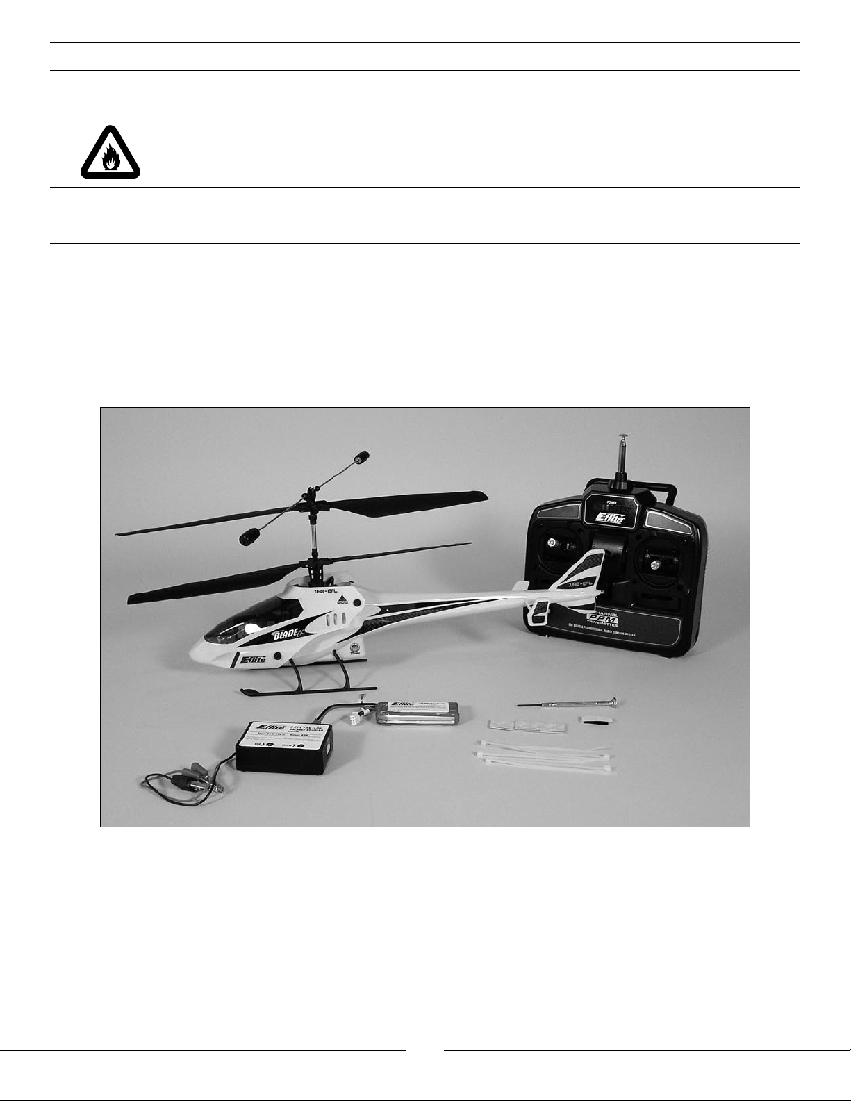
Blade CX RTF Contents
Item Description
N/A Blade CX RTF Airframe
EFLH1040 4CH Transmitter FM 72MHz
EFLB0990 7.4V 800mAh 2-Cell Li-Po, JST/Balance
EFLC3100 2-Cell Li-Po Balance Charger, 0.5A
EFLH1209 Mounting Accessories & Screwdriver
3
Page 4

Warranty Information
Horizon Hobby, Inc. guarantees this model to be free from defects in both material and workmanship at the date
of purchase. This warranty does not cover any component parts damaged by use or modification. In no case shall
Horizon Hobby’s liability exceed the original cost of the purchased kit. Further, Horizon Hobby reserves the right to
change or modify this warranty without notice.
In that Horizon Hobby has no control over the final assembly or material used for the final assembly, no liability
shall be assumed nor accepted for any damage resulting from the use of the final assembled product. By the act
of using the assembled product, the user accepts all resulting liability.
Please note that once assembly of the model has been started, you must contact Horizon Hobby, Inc. directly
regarding any warranty question. Please do not contact your local hobby shop regarding warranty issues, even
if that is where you purchased it. This will enable Horizon to better answer your questions and service you in the
event that you may need any assistance.
If the buyer is not prepared to accept the liability associated with the use of this product, the buyer is advised to
return this kit immediately in new and unused condition to the place of purchase.
Horizon Hobby, Inc.
4105 Fieldstone Road
Champaign, Illinois 61822
(877) 504-0233
horizonhobby.com
Battery Warnings, Guidelines and Charging
While the 7.4V 800mAh 2-cell Lithium Polymer Battery Pack (EFLB0990) included with your Blade™
CX features Charge Protection Circuitry and Balance Charging via the included 2-cell Lithium Polymer
Balance Charger (EFLC3100) to help ensure a safe charge every time, you MUST read the following
safety instructions and warnings before handling, charging or using the Li-Po battery pack.
Note: Lithium Polymer batteries are significantly more volatile than the alkaline, Ni-Cd or
Ni-MH batteries used in RC applications. All instructions and warnings must be followed exactly.
Mishandling of Li-Po batteries can result in fire.
By handling, charging or using the included Li-Po battery you assume all risks associated with lithium
batteries. If you do not agree with these conditions, return your complete Blade CX model in new,
unused condition to the place of purchase immediately.
4
Page 5

Battery Warnings, Guidelines and Charging (continued)
• You must charge the included 7.4V 800mAh 2-cell Li-Po battery pack in a safe area away from flammable
materials.
• Do not charge the battery when installed in the helicopter.
• Never charge the battery unattended. When charging the battery you should always remain in constant
observation to monitor the charging process and react to potential problems that may occur.
• After flight, the battery must be cooled to ambient temperature before charging.
• You MUST use the included 2-cell 7.4V Li-Po Balance Charger ONLY. Failure to do so may result in a fire
causing personal injury and/or property damage. DO NOT use a Ni-Cd or Ni-MH charger
.
• If at any time during the charge or discharge process the battery begins to balloon or swell, discontinue
charging or discharging immediately. Quickly and safely disconnect the battery, then place it in a safe, open
area away from flammable materials to observe it for at least 15 minutes. Continuing to charge or discharge
a battery that has begun to balloon or swell can result in a fire. A battery that has ballooned or swollen even a
small amount must be removed from service completely.
• In the event of a crash, you must quickly and safely disconnect and remove the battery from the model, then
place it in a safe, open area away from flammable materials to observe it for at least 15 minutes.
• Store the battery at room temperature for best results.
• When transporting or temporarily storing the battery, the temperature range should be from 40–120 degrees
Fahrenheit. Do not store the battery or model in a car or direct sunlight whenever possible. If stored in a hot
car, the battery can be damaged or even cause a fire.
• Do not over-discharge the battery. Discharging the battery too low can cause damage to the pack resulting in
reduced performance and duration. Follow the additional guidelines found in the “Flying the Blade CX” section
(page 25) to prevent over-discharge of the battery.
If you have any further questions or concerns regarding the handling, charging and/or use of the included Li-Po
battery pack, please contact Horizon Hobby’s Product Support staff at 1-877-504-0233.
5
Page 6
Battery Warnings, Guidelines and Charging (continued)
It is important that you only charge the included 7.4V 800mAh 2-cell Li-Po Battery Pack (EFLB0990)
with the included 2-cell 7.4V Li-Po Balance Charger (EFLC3100). Your battery pack is equipped with
special Charge Protection Circuitry and a Balance Charge Lead with connector that is only compatible
with this charger. Attempting to charge the pack using another Li-Po charger or non Li-Po compatible
charger could result in serious damage. Please familiarize yourself thoroughly with the warnings and
guidelines (pages 4–5) before continuing.
Note: The Li-Po battery pack included with your Blade™ CX will arrive partially charged. For this reason the initial
charge may only take approximately 1.0–1.5 hours.
The included 2-cell 7.4V Li-Po Balance Charger will charge a near fully discharged (not over-discharged)
7.4V 800mAh 2-cell Li-Po Battery Pack in approximately 2.0–2.5 hours. In some cases the charge time
may be shorter depending on the actual amount of capacity left in the pack after a flight. NEVER charge
the battery unattended.
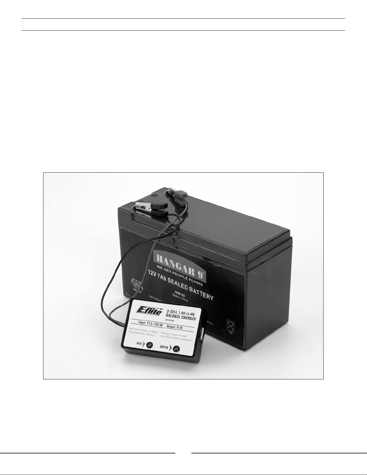
The charger requires up to 1.5 Amps of 11.5–15 Volt DC input power that can be supplied from a small 12V gel
cell or car battery.
6
Page 7
Battery Warnings, Guidelines and Charging (continued)
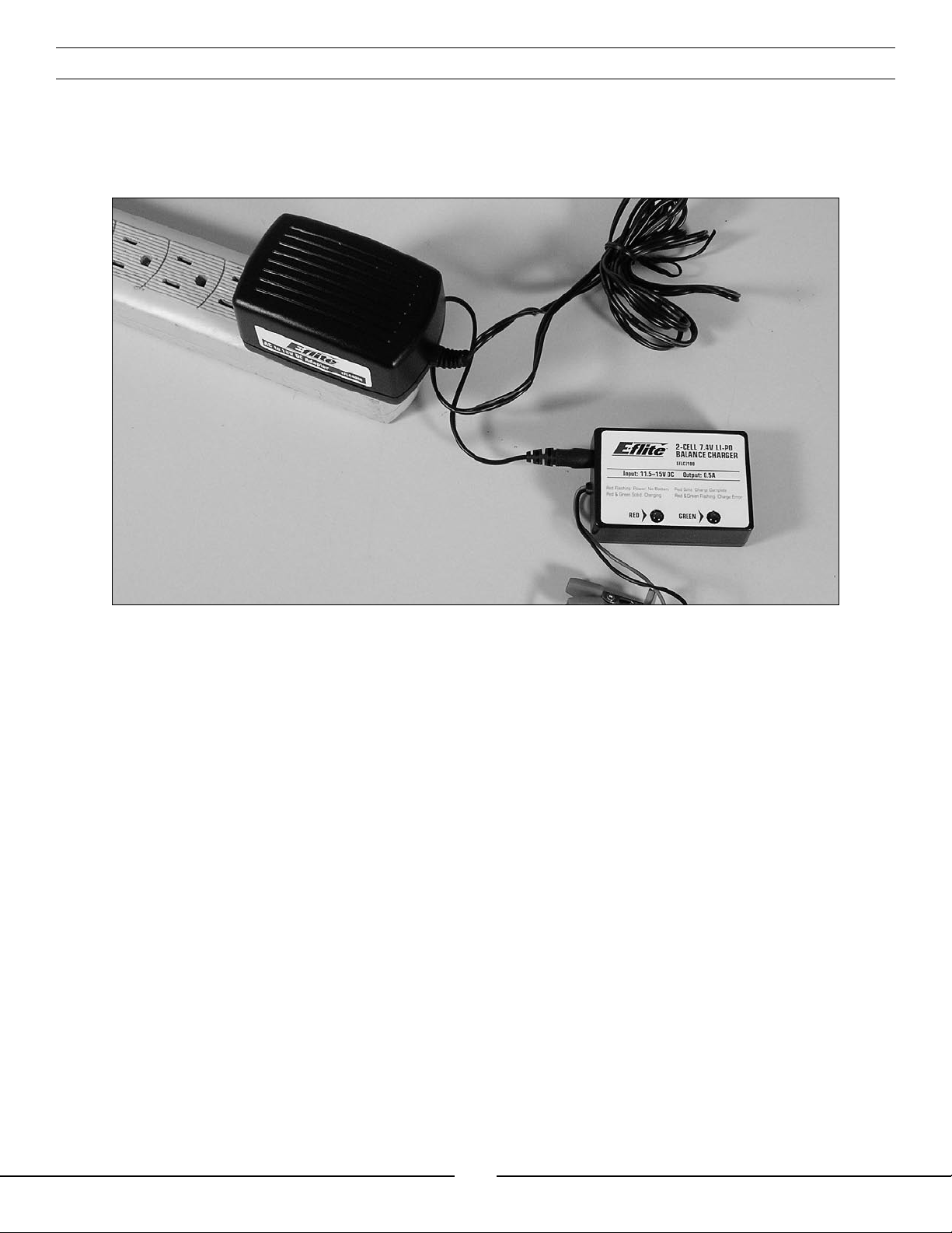
Input power for the charger can also be supplied through the use of an AC to DC adapter/power supply for
convenient charging anywhere an AC outlet is available. We recommend the optional E-flite™ AC to 12V DC, 1.5
Amp Power Supply (EFLC4000). NEVER attempt to power the charger from an AC outlet without the use of
a proper AC to DC adapter/power supply.
The charger is equipped with two LED indicators marked RED and GREEN on the label. These LEDs indicate the
following (also found on the label of the charger):
• Red Flashing LED Only: Input power with no battery connected
• Red and Green Solid LED: Battery connected and charging
• Red Solid LED Only: Charge complete
• Red and Green Flashing LED: Charge error
7
Page 8
Battery Warnings, Guidelines and Charging (continued)
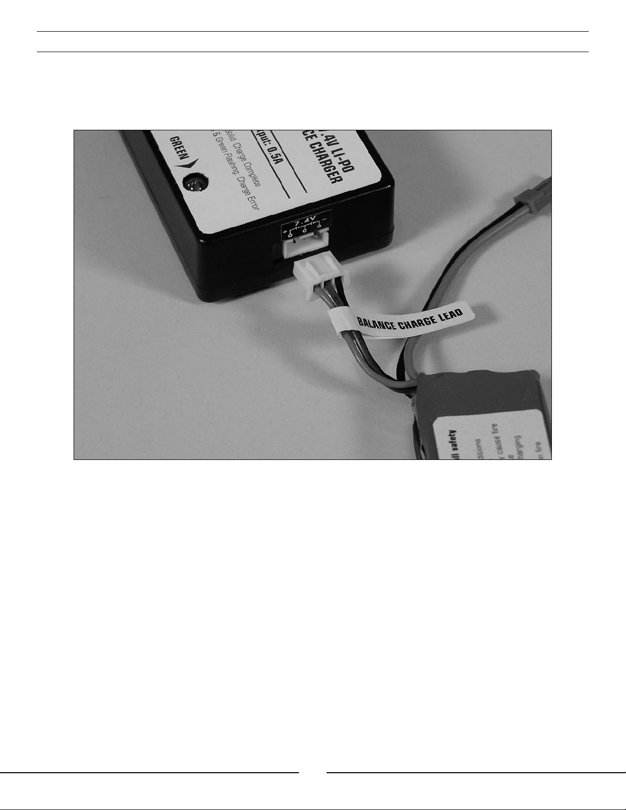
Once you have connected the charger to a power source (Use care to ensure proper polarity when connecting
the charger to the power source), its red LED will flash to indicate the charger has power and is ready to begin
charging. Connect the Li-Po battery pack to the charger using the specially marked Balance Charge Lead. The
connector is keyed to prevent reverse polarity connection.
When the battery is properly connected and charging normally, the red and green LED indicators will glow solid.
Once the battery has been fully charged, the green LED will go out, leaving just the red LED glowing solid. The
battery can now be removed from the charger and installed into the Blade™ CX for flight.
8
Page 9
Charge Errors and Indications
In the event that both the red and green LEDs flash, a charge error has occurred. Some examples of
charge errors and their indications include:
• Alternating flashing of the red and green LEDs will indicate that the charge process has been interrupted. If input
power to the charger has been interrupted due to disconnection from the power source or a drop in voltage/
current output from the power source, unplug the battery from the charger. Next, check to make sure that
the alligator clips are firmly and properly attached to the power source or that the input power plug from the
optional AC to 12V DC adapter/power supply is connected. Also be sure that the power source is providing the
proper amount of voltage and current required to the charger.
After confirming the connections and that the power source is delivering the necessary voltage and current, re-
start the charge process by connecting the battery pack. Continue to monitor the charge process to ensure that
no further charge errors occur.
• Simultaneous flashing of the red and green LEDs will indicate that the voltage of the Li-Po battery pack is
too low to allow the charge process to begin. In this case the battery may have been over-discharged due to
flying the model too long (For more information on preventing over-discharge of the Li-Po battery pack, see
the “Flying the Blade CX” section found on page 25), or that a single cell or even both cells in the battery pack
may be damaged.
If after several charging attempts you continue to see this charge error indication, you should remove the
battery pack from service and replace it with a new one.
If you have any further questions or concerns regarding charge error indications, please contact Horizon Hobby’s
Product Support staff at 1-877-504-0233.
Install the Transmitter Batteries
Install 8 new “AA” batteries in the included transmitter. Check the power level of the batteries and operation of the
transmitter by switching the power switch on (upward). The status LEDs at the top of the transmitter will indicate
the power level of the batteries. If at any time the status LEDs no longer show green, it will be necessary to
replace the batteries with new ones.
9
Page 10

Installing the Flight Battery
Use the included hook and loop material for mounting the Li-Po battery pack. The “hook” material is already
installed on the battery frame stop. Install the “loop” material on the end of the battery with the wire leads.
The battery can be installed through the opening in the rear of the body. Be sure to install the end of the battery
with the loop material first, with the wire leads oriented to the left side of the model so that they can pass by the
stop. Slide the battery into the support frame until the hook and loop material makes contact.
10
Page 11
Installing the Flight Battery (continued)
Quick Tip: You can install a tape “pull tab” on the end of the battery to make it easier to remove. You can also
carefully remove some additional material from the opening in the rear of the body.
Center of Gravity
Once the battery has been properly installed and secured you will need to check the helicopter’s center of gravity.
If the helicopter is not properly balanced it can be difficult to control and constantly try to move forward or
backward in hover.
To check the center of gravity, lift the helicopter by the stabilizer flybar with the flybar positioned perpendicular to
the tail section of the body. Make sure that the helicopter balances level. If it does not, confirm that the battery
has been properly installed and reposition if necessary.
Support by Flybar
Must Balance Level
11
Page 12

Control Test
Although each Blade™ CX model is test flown at the factory, it is a good idea to test the controls prior to the first
flight to ensure none of the servos, linkages or other parts were damaged during shipping and handling. Before
proceeding, disconnect both of the main motor plugs from the 4-in-1 control unit, making note of their direction
and polarities for proper re-installation after the control test is complete. It is not safe to perform the control test
with the main motor plugs connected to the 4-in-1 control unit after power up.
Turn the transmitter on first then plug the battery into the battery lead of the 4-in-1 unit.
12
Page 13

Control Test (continued)
Position the helicopter to view it from the left-hand side. Move the right-hand control stick on the transmitter
forward and back to check elevator pitch control. When the stick is pushed forward, the rear servo
should push the swashplate upward. When the stick is pulled back, the rear servo should pull the
swashplate downward.
13
Page 14

Control Test (continued)
Position the helicopter to view it from the right-hand side. Move the right-hand control stick on the transmitter
left and right to check aileron roll control. When the stick is pushed to the left, the forward servo should
push the swashplate upward. When the stick is pushed to the right, the forward servo should pull the
swashplate downward.
If at any time during the test the controls do not respond properly, double-check the location of the servo
connections on the 4-in-1 unit. These should be positioned as follows (when viewing the helicopter from behind):
Channel 1 (Lower Port) – Forward aileron servo
Channel 2 (Upper Port) – Rear elevator servo
Once you have confirmed that the servo connection locations are correct, all controls should be functioning
properly. If you do encounter any problems with your Blade CX responding properly to the transmitter, do not fly.
Contact Horizon Hobby’s Product Support staff at 1-877-504-0233.
If you have confirmed proper control operation of your Blade™ CX, reconnect the main motor plugs to the 4-in-1
unit, taking care to keep the proper polarity and location of each as they were before the test. Use the label on the
4-in-1 unit for reference of the proper polarity and locations. Note that the red wire leads are positive (+) and the
black wire leads are negative (−).
14
Page 15

4-in-1 Control Unit Description, Arming and Motor Control Test
The unique 4-in-1 Control Unit installed on your Blade™ CX is a lightweight combination of 4-channel FM receiver,
main motor mixer, main motor electronic speed controls, and piezo gyro. The 4-in-1 unit also contains a main
motor proportional mix trimmer pot and status LED.
Main Motor Proportional
Mix Trimmer Pot
Receiver
Crystal
Antenna Wire
The following checklist contains the steps you must follow to ensure proper arming and operation of the 4-in-1 unit
as well as proper motor control response:
• Each time before you fly you must ALWAYS turn on the transmitter power first before connecting
the flight battery to the 4-in-1 unit. Never connect the flight battery to the 4-in-1 unit before first
powering on the transmitter. Never turn off the transmitter before disconnecting the flight battery
from the 4-in-1 unit first. Also, be certain to fully extend the transmitter antenna before flight.
Status
LED
Motor Plugs
Servo Plugs
• Both the throttle (left-hand) stick and throttle trim MUST be in their lowest possible position in order
for the 4-in-1 unit to arm the electronic speed controls for the main motors (see photo found on page
16 for reference).
• If this is the first test flight, or a test flight following repairs, you will also want to center the rudder, aileron and
elevator trims (
see photo found on page 16 for reference).
15
Page 16

4-in-1 Control Unit Description, Arming and Motor Control Test (continued)
Elevator Trim
Throttle Trim
Set Throttle
Trim and
Throttle Stick
at Lowest
Position
Aileron Trim
Rudder Trim
• After confirming that the transmitter has been turned on and has an adequate level of battery power as
displayed by the LEDs at the top of the transmitter, it is now safe to connect the flight battery to the 4-in-1 unit.
• With battery power applied, the 4-in-1 unit status LED will blink red, and then blink green. It is
extremely important that you do not move or sway the helicopter once the status LED begins to
blink green confirming that the initialization process and calibration of the gyro has begun. It is OK to
move the model when the status LED is blinking red (as in the time it takes to connect the flight battery to the
4-in-1 unit and place the model at rest), as long as the model remains motionless when the status LED begins to
blink green.
• When the status LED becomes solid green, the unit is armed and ready for flight. Use caution as both
main motors will now run with throttle stick or throttle trim input. Do not advance the throttle stick or trim until
you are clear of the rotor blades and ready to fly.
Note: If the status LED does not become solid green, please review the following:
• If after blinking red the status LED becomes solid red, you have a positive Radio Frequency (RF) link between
the transmitter and receiver of the 4-in-1 unit, but the throttle stick and throttle trim may not be in their lowest
possible positions. Check to be sure that both the throttle stick and throttle trim are in their lowest possible
position and the status LED should blink green then become solid green indicating the unit is armed and ready
for flight. Proceed to the next step of the checklist once the unit is armed.
16
Page 17

4-in-1 Control Unit Description, Arming and Motor Control Test (continued)
• If after blinking red the status LED continues to flash from green to red, you do not have a positive RF link
between the transmitter and receiver of the 4-in-1 unit. First, check to be sure that the transmitter has been
powered on and has an adequate level of battery power. If the transmitter was indeed powered on, power both
the transmitter and 4-in-1 unit down, then check that the crystal in the transmitter and the crystal in the 4-in-1
are properly seated and secured in their mounts. Once you have confirmed the crystals are properly seated
and secured, turn on the transmitter and then connect the flight battery to the 4-in-1 unit. The 4-in-1 unit should
now arm normally.
If your 4-in-1 unit will not arm after following the guidelines as listed above, contact Horizon Hobby’s Product
Support staff at 1-877-504-0233.
• Once you have placed the helicopter in a safe area to fly, free from obstructions, and are clear of the rotor
blades, you can safely begin to power up the model. We recommend an indoor area with at least 20-feet by 20feet of floor space and no less than 8-foot ceilings. If you have to take your first flight outside, pick a time when
wind conditions are calm.
• Advance the throttle (left-hand) stick slowly, just until the main rotor blades begin to spin. Be sure not to advance
the throttle stick too far to keep the helicopter from lifting off the ground. Note the direction that each of the
main rotor blades spins. When viewed from the top, the lower main rotor blade should spin clockwise and the
upper main rotor blade should spin counterclockwise. If either rotor blade is operating in the wrong direction,
unplug the battery, then simply reverse its motor plug polarity on the 4-in-1 unit. Note that the proper polarity is
marked on the label of the 4-in-1 unit.
• After confirming that the direction of rotation for both rotor blades is correct, it is best to confirm that both
rotor blades respond properly to rudder control inputs. With both main rotor blades spinning at a low level of
power, move the rudder (left-hand) stick all the way to the right. This should cause the speed of the upper main
rotor blade to increase, and the speed of the lower main rotor blade to decrease. Next, move the rudder stick
all the way to the left. This should cause the speed of the lower main rotor blade to increase and the speed of
the upper main rotor blade to decrease. If both rotor blades are not responding properly to rudder input, simply
reverse the locations of their motor plugs on the 4-in-1 unit. Note that the proper motor plug locations are
marked on the label of the 4-in-1 unit.
• After confirming both main rotor blades respond properly to rudder inputs, your Blade™ CX is now ready for
flight.
17
Page 18

Before the First Flight
If the Blade™ CX is your first helicopter model, we suggest that you install the optional Training Gear Set
(EFLH1205) before making your first flight. The training gear helps to further increase the stability of the
model while also providing added support and cushioning to prevent tip-overs and damage to the model from
abrupt landings.
Installing the training gear takes only a few minutes following these steps:
• The Training Gear Set includes four training gear rods with plastic balls installed, four training gear rod to
landing skid attachments, four screws and one training gear rod mounting base.
• Locate the four training gear rod to landing skid attachments and four screws. Note that there are two each
of two types of attachments. Carefully snap two of the attachments to the landing skids forward of the landing
skid struts. The side of the attachment with the large hole should face outward, away from the helicopter, and
forward to the front of the helicopter. Next, carefully snap the remaining two attachments to the landing skids
behind the landing skid struts. The side of the attachment with the large hole should face outward, away from
the helicopter, and backward to the rear of the helicopter.
18
Page 19

Before the First Flight (continued)
• Once you have installed all four attachments, install the four screws making sure that they thread properly into
the back side of the attachment. It may be helpful to squeeze the attachment with a pair of pliers to make it
easier to thread the screw into the backside of the attachment. Do not tighten the screws all the way at this
time as the attachments will need to be adjusted for proper alignment once the training gear rods are installed.
• Locate the four training gear rods and rod mounting base. Note that the rod mounting base has four channels
into which the training gear rods will mount. The open side of these channels will face upward toward the
bottom of the helicopter when properly installed.
Carefully pass each of the rods through the attachments on the landing skids and into the channels on the base.
Take care to not pull the landing skids out of their mounts in the battery supports.
19
Page 20

Before the First Flight (continued)
• After ensuring that the rods are secure in the base, adjust the positions of the attachments on the landing skids
so that the base is centered under the main shaft of the helicopter. Once confirming the base is centered under
the main shaft, make sure that each of the landing skids is still firmly installed in the mounts of the battery
supports. Note that the landing skids may be pulled slightly inward under pressure of the training gear rods.
• With the attachments, rods and base properly positioned, you can now tighten the attachment screws until they
are just snug. Take care when tightening the screws to prevent stripping the backside of the attachments.
• Adjust the position of the tubing keepers and plastic balls on the training gear rods so that the balls are
positioned approximately 1/8” from the end of each rod. Be sure that the tubing keepers are positioned so that
the plastic ball can still spin freely on the rod.
Your Blade™ CX is now ready for flight.
20
Page 21

Before the First Flight (continued)
If you are not familiar with the controls of the helicopter, please take a few minutes to familiarize
yourself with them before attempting your first flight.
The left-hand stick controls both throttle (ascend/descend) and rudder (yaw left/right). When the throttle is in
the lowest position the main rotor blades will not spin. Advancing the stick upward will increase the speed of
the main rotor blades. Increasing the speed of the main rotor blades will cause the model to ascend.
Decreasing the speed of the main rotor blades by lowering the stick will cause the model to descend. After
lifting the model off the ground you can balance the throttle so that the model will hold a stationary hover
without ascending or descending.
You can also use the throttle trim to adjust the throttle value for a given stick position. For example, raising the
throttle trim will allow the model to hover at a lower throttle stick position.
Throttle Trim
21
Page 22

Before the First Flight (continued)
Moving the stick to the left will turn (yaw) the nose of the helicopter to the left about the axis of the main shaft.
This is accomplished by increasing the speed of the lower main rotor blade while decreasing the speed of the
upper main rotor blade. Moving the stick to the right will turn (yaw) the nose of the helicopter to the to the right
about the axis of the main shaft. This is accomplished by increasing the speed of the upper main rotor blade while
decreasing the speed of the lower main rotor blade.
The rudder trim can be used to help keep the nose of the helicopter from rotating to the left or right when in hover
with no rudder stick input. For example, if the nose of the helicopter drifts to the right when in hover, add left
rudder trim until the nose stays as close to straight as possible. Also note that further adjustments to the rudder
trim can be made using the Main Motor Proportional Mix Trimmer Pot as outlined on page 26.
Rudder Trim
The right-hand stick controls both elevator (pitch fore/aft) and aileron (roll). Pushing the stick forward will pitch the
nose of the helicopter downward, allowing the helicopter to be flown forward. Pulling the stick backward will pitch
the tail of the helicopter downward, allowing the helicopter to be flown backward.
The elevator trim can be used to help keep the helicopter from drifting forward or backward when in hover with
no elevator stick input. For example, if the helicopter drifts forward when in hover, add back elevator trim until the
helicopter hovers as level as possible with no forward drifting.
Elevator Trim
22
Page 23

Before the First Flight (continued)
Moving the stick to the left will roll the helicopter to the left, allowing the helicopter to be flown to the left. Moving
the stick to the right will roll the helicopter to the right, allowing the helicopter to be flown to the right.
The aileron trim can be used to help keep the helicopter from drifting left or right when in hover with no aileron
stick input. For example, if the helicopter drifts to the right when in hover, add left aileron trim until the helicopter
hovers as level as possible with no drifting to the right.
Aileron Trim
Once you have become familiar with the controls of the helicopter and are ready to fly, it will be time
to choose an area for the first flight. You will want to select a large, open area that is free of people
and obstructions. We recommend an indoor area with at least 20-feet by 20-feet of floor space and
no less than 8-foot ceilings. If you have to make your first flight outdoors, pick a time when wind
conditions are calm.
23
Page 24

Flying the Blade™ CX
Having followed the proper 4-in-1 control unit arming procedure, confirmed proper control of the
servos and motors, and found a suitable flying area, your Blade CX is ready for flight.
In addition to reviewing the flight maneuvers outlined below, we recommend that you watch the included
Instructional Video CD to see many of these maneuvers and adjustments performed by the Blade CX and pilot.
• Slowly raise the throttle stick, increasing the speed of the main rotor blades until the model begins to lift off.
Do not raise the throttle stick too quickly as the model could climb too fast causing you to lose control or make
contact with objects above.
• Lift the model off the ground just a few inches and concentrate on balancing the throttle stick position so that
the model holds a steady hover altitude. In some cases it may be best to make a few short “hops” to an altitude
of just a few inches until you become familiar with the control inputs and trim settings required to maintain a
steady hover and altitude. As you will find, the Blade™ CX requires minor throttle adjustments to maintain its
altitude in hover. Remember to keep these throttle adjustments as minimal as possible as large adjustments
could result in a loss of control and/or a possible crash.
• While attempting to establish a low-level hover, you can also check to see if any trim adjustments are required
to help keep the Blade CX from constantly drifting in various directions. If you find the helicopter constantly
drifts without any directional control input, it will be best to land the model before making any adjustments
to the trim levers. Additional details regarding the location and function of the trim levers can be found in the
“Before the First Flight” section of this manual (page 21-23).
If the nose of the helicopter is drifting to the left or right, you will need to adjust the rudder trim. You can also
adjust the Main Motor Proportional Mix if you experience any difficulties in trimming nose drift with the rudder
trim lever only. Please see the “Main Motor Proportional Trimmer Pot Description and Adjustment” section of this
manual for more details (page 26).
If the helicopter is drifting forward or backward, you will need to adjust the elevator trim.
If the helicopter is drifting to the left or right, you will need to adjust the aileron trim.
Continue to make trim adjustments until the helicopter can hover at a low altitude with very little drifting and
directional control input. If the Blade CX is your first helicopter model, it may be best to have the help of an
experienced helicopter pilot to trim the model for you before making your first flight.
• Once you have the Blade CX properly trimmed and maintaining a stable low-level hover, practice using the
rudder, elevator and aileron controls to get a feel for how the helicopter responds to control inputs. Remember
to keep the control inputs as minimal as possible to prevent over-controlling the helicopter, especially when in
hover. Additional details regarding the control functions can be found in the “Before the First Flight” section of
this manual (page 21-23).
• After becoming comfortable with hovering the Blade CX at low-levels of altitude just a few inches off the ground,
you can transition to hovering and flying the helicopter at higher altitudes of approximately three to four feet. At
these higher altitudes you will be able to get a feel for the flight characteristics of the Blade CX when it is flying
out of “ground effect.”
• If at any time during flight you feel like the helicopter is drifting out of control, simply release all of the controls
except for throttle. You will need to use the throttle to maintain altitude, but due to the inherent stability of the
coaxial counter-rotating blades, the Blade CX will simply return to a stable hover on its own if space allows.
24
Page 25

Flying the Blade CX (continued)
• Don’t be afraid to set the helicopter down on the ground quickly by lowering the throttle when approaching walls
or other obstacles to help prevent main rotor blade strikes. The optional Training Gear Set (EFLH1205) shown
in the “Before the First Flight” section of this manual (page 18–21) will help to further prevent damage to the
helicopter in the event that you must make an abrupt landing to avoid walls or other obstacles.
• I n the unfortunate event of a crash or rotor blade strike, no matter how minor or major, you MUST
lower both the throttle stick and throttle trim to their lowest possible position as quickly as possible
to prevent damage to the ESCs of the 4-in-1 unit.
• It is extremely important when hovering and flying the Blade CX to be aware of the power level
of the Li-Po battery pack. If at any time the helicopter begins to require more throttle than typical
to maintain hover or flight, or has lost the ability to maintain hover or flight due to significant loss
of power, you must land the helicopter and power the motors down IMMEDIATELY to prevent
over-discharge of the Li-Po battery pack. If you continue to run the motors after noticing a loss
in power it is possible to discharge the Li-Po battery pack too far, causing permanent damage to
the pack. Over-discharge of the Li-Po battery pack can result in shortened flight times, loss of power
output or failure of the pack entirely.
• Once you have gained experience and confidence in hovering the Blade CX, you can attempt more advanced
maneuvers including:
Forward Flight
Backward Flight
Pirouettes
Skidding Take Offs
Skidding Landings
Spot Landings
25
Page 26

Main Motor Proportional Mix Trimmer Pot Description and Adjustment
The Main Motor Proportional Mix Trimmer Pot can be found on the left side of the 4-in-1 control unit. This
“proportional” trimmer pot adjusts the amount of mixing between the main motors allowing you to “fine-tune” the
rudder trim (sub-trim) to help prevent the nose from drifting to the left or right when in hover.
Main Motor
Proportional Mix
Trimmer Pot
In a stable hover, with the rudder trim centered and no rudder control input, note toward which direction the nose
of the helicopter is trying to drift. If the nose of the helicopter is drifting to the left, you will want to increase power
to the right-hand motor (spinning the upper main rotor blade). This is accomplished by turning the “proportional”
trimmer pot clockwise.
If the nose of the helicopter is drifting to the right in hover, you will want to increase the power to the left-hand
motor (spinning the lower main rotor blade). This is accomplished by turning the “proportional” trimmer pot
counterclockwise.
Note: You must always power down the 4-in-1 unit before making adjustments to the proportional
mix trimmer pot. Any changes made to the trimmer pot will not take effect until the 4-in-1 unit is reinitialized and re-armed.
Note: Be sure to use the proper size and type of screwdriver to carefully make adjustments to the trimmer pot.
Use of the improper size and type of screwdriver or too much force can damage the trimmer pot. Also be sure
to take your time when making adjustments to the proportional trimmer pot as it may only require very slight
adjustment to achieve the desired level of performance.
As the battery output voltage decreases throughout the flight, it may be necessary to make small adjustments
to the rudder trim or rudder control input in order to keep the nose of the helicopter straight. These small
adjustments can be made using the rudder trim lever or rudder control stick and do not require additional
adjustments of the proportional trimmer pot.
26
Page 27

Upper Main Rotor Blade Tracking Adjustment
Caution: Be sure to maintain a safe distance from the helicopter (approximately 10–15 feet) when
tracking the Upper Main Rotor Blade.
Your Blade™ CX is equipped with an adjustable linkage between the Stabilizer Flybar and Upper Main Rotor Blade.
This linkage allows you to adjust the tracking of the upper main rotor blade for smoother and more stable flight
performance.
• You can check the upper main rotor blade tracking either on the ground or in the air at eye level. It might be a
good idea to have an assistant on hand to help sight the blade tracking.
• Once the main rotor blades have been brought up to speed, note whether the tips of the upper main rotor blade
are tracking in the same plane or not.
• If the tips are not tracking in the same plane, power the helicopter down to make adjustments to the adjustable
linkage. You can start by turning the ends of the linkage in one-half to one-full turn at a time. Power the
helicopter up again and re-check the blade tracking. If the tracking has gotten better, continue to turn the ends
of the linkage in one-half to one-full turn at a time until the tips are tracking in the same plane.
If the tracking has gotten worse after first turning the ends of the adjustable linkage in, turn the ends of the
linkage back out one-half to one-full turn at a time. If the tracking has gotten better, continue to turn the ends of
the linkage out one-half to one-full turn at a time until the tips are tracking in the same plane.
27
Page 28

Upper Main Rotor Blade Tracking Adjustment (continued)
Tips Out Of Track —
Adjustment Necessary
Tips In Track — No
Adjustment Necessary
Typically, not much adjustment should be necessary to properly track the tips of the upper main rotor blade.
However, due to the small size of the linkage ends and threaded rods it may not always be possible to achieve
absolutely perfect blade tracking. Don’t worry as the helicopter will still perform well as long as the blade tracking
is adjusted as closely as possible.
Note: It will not be necessary to adjust the Lower Main Rotor Blade tracking as fixed links are used between the
rotor blade and swashplate.
28
Page 29

Main Motor Care and Installing the Optional Main Motor Heat Sink
The 180 motors used to power your Blade™ CX are of the closed end-bell variety and do not require any special
maintenance. We do, however, suggest that you allow the motors to cool to near ambient temperature between
flights/battery pack changes to prevent accelerated motor wear due to excess motor heat.
You will find the performance and life of the 180 main motors to be very good, however, installation of the optional
Main Motor Heat Sink (EFLH1208) can help to further improve motor cooling during flight, resulting in improved
motor performance and longer motor life.
Installing the main motor heat sink takes only a few minutes following these steps:
• Installation of the main motor heat sink will require that you to temporarily remove the right-hand main motor
from the main frame. This is easily accomplished by removing the two motor mounting screws found on the
bottom of the main frame.
• With the right-hand main motor removed from the frame, you can press the main motor heat sink into place
near the top/end of the left-hand main motor. We recommend that you use Heat Sink Compound (EFLM1913) on
any surfaces of the heat sink that make contact with the motor case to further improve the effectiveness of the
heat sink. The wider end of the heat sink (more fins) must be placed toward the front of the helicopter.
29
Page 30

Main Motor Care and Installing the Optional Main Motor Heat Sink (continued)
• You can now press the right-hand main motor into place in the heat sink and use the motor mounting screws to
re-install the motor on the main frame. Again, we recommend that you use Heat Sink Compound (EFLM1913) on
any surfaces of the heat sink that make contact with the motor case to further improve the effectiveness of the
heat sink.
The main motor heat sink is now installed and ready for flight.
30
Page 31

2005 Official AMA National Model Aircraft Safety Code
GENERAL
1) I will not fly my model aircraft in sanctioned events, air shows or model flying demonstrations until it has been
proven to be airworthy by having been previously, successfully flight tested.
2) I will not fly my model higher than approximately 400 feet within 3 miles of an airport without notifying the
airport operator. I will give right-of-way and avoid flying in the proximity of full-scale aircraft. Where necessary, an
observer shall be utilized to supervise flying to avoid having models fly in the proximity of full-scale aircraft.
3) Where established, I will abide by the safety rules for the flying site I use, and I will not willfully or deliberately fly
my models in a careless, reckless and/or dangerous manner.
4) The maximum takeoff weight of a model is 55 pounds, except models flown under Experimental Aircraft rules.
5) I will not fly my model unless it is identified with my name and address or AMA number on or in the model. (This
does not apply to models while being flown indoors.)
6) I will not operate models with metal-bladed propellers or with gaseous boosts, in which gases
other than air enter their internal combustion engine(s); nor will I operate models with extremely hazardous fuels
such as those containing tetranitromethane or hydrazine.
RADIO CONTROL
1) I will have completed a successful radio equipment ground range check before the first flight of a new or
repaired model.
2) I will not fly my model aircraft in the presence of spectators until I become a qualified flier, unless assisted by
an experienced helper.
3) At all flying sites a straight or curved line(s) must be established in front of which all flying takes place with the
other side for spectators. Only personnel involved with flying the aircraft are allowed at or in front of the flight
line. Intentional flying behind the flight line is prohibited.
4) I will operate my model using only radio control frequencies currently allowed by the Federal Communications
Commission. (Only properly licensed Amateurs are authorized to operate equipment on Amateur Band
frequencies.)
5) Flying sites separated by three miles or more are considered safe from site-to site interference, even when
both sites use the same frequencies. Any circumstances under three miles separation require a frequency
management arrangement, which may be either an allocation of specific frequencies for each site or testing to
determine that freedom from interference exists. Allocation plans or interference test reports shall be signed
by the parties involved and provided to AMA Headquarters. Documents of agreement and reports may exist
between (1) two or more AMA Chartered Clubs, (2) AMA clubs and individual AMA members not associated with
AMA Clubs, or (3) two or more individual AMA members.
6) For Combat, distance between combat engagement line and spectator line will be 500 feet per cubic inch
of engine displacement. (Example: .40 engine = 200 feet.); electric motors will be based on equivalent
combustion engine size. Additional safety requirements will be per the RC Combat section of the current
Competition Regulations.
7) At air shows or model flying demonstrations, a single straight line must be established, one side of which is for
flying, with the other side for spectators.
8) With the exception of events flown under AMA Competition rules, after launch, except for pilots or helpers being
used, no powered model may be flown closer than 25 feet to any person.
9) Under no circumstances may a pilot or other person touch a powered model in flight.
31
Page 32

Replacement Parts List
EFLH1200 . . . . . . . . . . . . . . . . . . . . . Blade CX RTF Electric Coaxial Heli
EFLB0990 . . . . . . . . . . . . . . . . . . . . . 7.4V 800mAh 2-Cell Li-Po, JST/Balance
EFLC3100 . . . . . . . . . . . . . . . . . . . . . 2-Cell Li-Po Balance Charger, 0.5A
EFLH1017 . . . . . . . . . . . . . . . . . . . . . FM Crystal Set CH17, 72.130: BCP, BCX
EFLH1019 . . . . . . . . . . . . . . . . . . . . . FM Crystal Set CH19, 72.170: BCP, BCX
EFLH1021 . . . . . . . . . . . . . . . . . . . . . FM Crystal Set CH21, 72.210: BCP, BCX
EFLH1025 . . . . . . . . . . . . . . . . . . . . . 4-in-1 Control Unit FM 72MHz: BCX
EFLH1040 . . . . . . . . . . . . . . . . . . . . . 4CH Transmitter FM 72MHz: BCX
EFLH1045 . . . . . . . . . . . . . . . . . . . . . Transmitter Antenna: BCP, BCX
EFLH1050 . . . . . . . . . . . . . . . . . . . . . FM Crystal Set CH50, 72.790: BCP, BCX
EFLH1052 . . . . . . . . . . . . . . . . . . . . . FM Crystal Set CH52, 72.830: BCP, BCX
EFLH1054 . . . . . . . . . . . . . . . . . . . . . FM Crystal Set CH54, 72.870: BCP, BCX
EFLRS75 . . . . . . . . . . . . . . . . . . . . . . 7.5 Gram Sub-Micro S75 Servo
EFLRS751 . . . . . . . . . . . . . . . . . . . . . Gear Set: S75
EFLRS752 . . . . . . . . . . . . . . . . . . . . . Case Set: S75
EFLH1121 . . . . . . . . . . . . . . . . . . . . . Bearing 2x6x3mm (2): BCP, BCX
EFLH1209 . . . . . . . . . . . . . . . . . . . . . Mounting Accessories & Screwdriver: BCX
EFLH1210 . . . . . . . . . . . . . . . . . . . . . 180 Motor w/8T 0.5M Pinion Left: BCX
EFLH1211 . . . . . . . . . . . . . . . . . . . . . 180 Motor w/8T 0.5M Pinion Right: BCX
EFLH1212 . . . . . . . . . . . . . . . . . . . . . Inner Shaft w/Hub & Main Gear Set: BCX
EFLH1213 . . . . . . . . . . . . . . . . . . . . . Outer Shaft & Main Gear Set: BCX
EFLH1214 . . . . . . . . . . . . . . . . . . . . . Shaft Retaining Collar Set: BCX
EFLH1215 . . . . . . . . . . . . . . . . . . . . . Bearing 4x8x3mm (2): BCX
EFLH1216 . . . . . . . . . . . . . . . . . . . . . Swashplate Set: BCX
EFLH1217 . . . . . . . . . . . . . . . . . . . . . Lower Rotor Head & Linkage Set: BCX
EFLH1218 . . . . . . . . . . . . . . . . . . . . . Servo Pushrod Set: BCX
EFLH1219 . . . . . . . . . . . . . . . . . . . . . Stabilizer Flybar Set: BCX
EFLH1220 . . . . . . . . . . . . . . . . . . . . . Lower Main Blade Set (2 pair): BCX
EFLH1221 . . . . . . . . . . . . . . . . . . . . . Upper Main Blade Set (2 pair): BCX
EFLH1222 . . . . . . . . . . . . . . . . . . . . . Landing Skid Set: BCX
EFLH1223 . . . . . . . . . . . . . . . . . . . . . Battery Support Set: BCX
EFLH1224 . . . . . . . . . . . . . . . . . . . . . Main Frame Set: BCX
EFLH1225 . . . . . . . . . . . . . . . . . . . . . Hardware Set: BCX
EFLH1226 . . . . . . . . . . . . . . . . . . . . . Body Mount Rod & Grommet Set: BCX
EFLH1227 . . . . . . . . . . . . . . . . . . . . . Front Body: BCX
EFLH1228 . . . . . . . . . . . . . . . . . . . . . Rear Body: BCX
EFLH1229 . . . . . . . . . . . . . . . . . . . . . Complete Body Set: BCX
Optional Parts List
EFLC4000 . . . . . . . . . . . . . . . . . . . . . AC to 12V DC, 1.5 Amp Power Supply
EFLH1205 . . . . . . . . . . . . . . . . . . . . . Training Gear Set: BCX
EFLH1208 . . . . . . . . . . . . . . . . . . . . . Main Motor Heat Sink: BCX
EFLM1913 . . . . . . . . . . . . . . . . . . . . . Heat Sink Compound, 5g
EFLH1230 . . . . . . . . . . . . . . . . . . . . . Front Body, Police: BCX
EFLH1231 . . . . . . . . . . . . . . . . . . . . . Rear Body, Police: BCX
EFLH1232 . . . . . . . . . . . . . . . . . . . . . Complete Body Set, Police: BCX
Please see your favorite retailer or visit our web site (www.E-fliteRC.com) to find the latest in new replacement
and option parts releases for your Blade™ CX.
32
Page 33

Replacement and Optional Parts
RX
TX
RX
TX
RX
TX
RX
TX
RX
TX
RX
TX
2-CELL 7.4V LI-PO
BALANCE CHARGER
EFLC3100
Input: 11.5-15V DC Output: 0.5A
EFLB0990
7.4V 800mAh 2-Cell Li-Po
RED
GREEN
FM Crystal Set CH 54,
72.870: BCP, BCX
FM Crystal Set CH 17,
72.130: BCP, BCX
FM Crystal Set CH 19,
72.170: BCP, BCX
FM Crystal Set CH 21,
72.210: BCP, BCX
FM Crystal Set CH 50,
72.790: BCP, BCX
FM Crystal Set CH 52,
72.830: BCP, BCX
4-in-1 Control Unit FM
72MHz: BCX
7.5 Gram Sub-Micro S75 Servo
4CH Transmitter FM
72MHz:BCX
2-Cell Li-Po Balance Charger,
0.5A
7.4V 800mAh 2-Cell Li-Po,
JST/Balance
Bearing 2x6x3mm (2): BCP, BCX
AC to 12VDC,
1.5 Amp Power Supply
Main Motor Heat Sink: BCX
Mounting Accessories&
Screwdriver: BCX
180 Motor w/8T 0.5M
Pinion Left: BCX
180 Motor w/8T 0.5M
Pinion Right: BCX
Inner Shaft w/Hub &
Main Gear Set: BCX
Shaft Retaining Collar Set: BCX Bearing 4x8x3 (2): BCX
Swashplate Set: BCX Lower Rotor Head & Linkage Set: BCX
Servo Pushrod Set: BCX
Stabilizer Flybar Set: BCX
Lower Main Blade Set
(2 pair): BCX
Upper Main Blade Set
(2 pair): BCX
Landing Skid Set: BCX
Transmitter Antenna: BCP, BCX
Battery Support Set: BCX Main Frame Set: BCX Hardware Set: BCX
Body Mount Rod &
Grommet Set: BCX
Training Gear Set: BCX
Complete Body Set: BCX
Front Body: BCX Rear Body: BCX
Complete Body Set, Police: BCX
Rear Body, Police: BCX
Outer Shaft
& Main
Gear Set: BCX
Front Body, Police: BCX
ELFH1017
EFLH1019 EFLH1021
EFLH1050 EFLH1052 EFLH1054
ELFH1025
EFLRS75 EFLH1040
EFLC3100 EFLB0990
EFLH1121
ELFC4000
EFLH1208
EFLH1209
EFLH1210 EFLH1211 EFLH1212
EFLH1214 EFLH1215 EFLH1216 EFLH1217
EFLH1219 EFLH1220 EFLH1221 EFLH1222EFLH1218
EFLH1224 EFLH1225 EFLH1226 EFLH1205
EFLH1045
EFLH1223
EFLH1227 EFLH1228
EFLH1229
EFLH1230 EFLH1231
EFLH1232
ELFH1213
33
Page 34

Exploded View Parts Listing
Exploded
Reference
View
Number
Description
(Quantity Required)
Included
In Item
Number
001. . . . . . . . . . . . . . Stabilizer Flybar Rubber Tip (2) . . . . . . . . . . . . EFLH1219
002. . . . . . . . . . . . . . Stabilizer Flybar Weight (2) . . . . . . . . . . . . . . EFLH1219
003. . . . . . . . . . . . . . Stabilizer Flybar (1) . . . . . . . . . . . . . . . . . . . . EFLH1219
004. . . . . . . . . . . . . . Upper Main Blade (2) . . . . . . . . . . . . . . . . . . EFLH1221
005. . . . . . . . . . . . . . 1.2 x 6mm Screw (5) . . . . . . . . . . . . . . . . . . EFLH1225
006. . . . . . . . . . . . . . Stabilizer Flybar Hub/Holder (1) . . . . . . . . . . . EFLH1212
007. . . . . . . . . . . . . . Upper Rotor Head & Inner Shaft (1) . . . . . . . . . EFLH1212
008. . . . . . . . . . . . . . Stabilizer Flybar Linkage (1) . . . . . . . . . . . . . . EFLH1219
009. . . . . . . . . . . . . . Bearing 2mm x 6mm x 3mm (2) . . . . . . . . . . . EFLH1121
010. . . . . . . . . . . . . . Bearing Holder (1) . . . . . . . . . . . . . . . . . . . . . EFLH1217
011. . . . . . . . . . . . . . Outer Shaft (1) . . . . . . . . . . . . . . . . . . . . . . . . EFLH1213
012. . . . . . . . . . . . . . Lower Rotor Head (1) . . . . . . . . . . . . . . . . . . . EFLH1217
013. . . . . . . . . . . . . . M2 x 2.5mm Screw (5) . . . . . . . . . . . . . . . . . EFLH1225
014. . . . . . . . . . . . . . Lower Main Blade (2) . . . . . . . . . . . . . . . . . . . EFLH1220
015. . . . . . . . . . . . . . Lower Rotor Head/Swash Linkage (2) . . . . . . . EFLH1217
016. . . . . . . . . . . . . . Upper Swashplate (1) . . . . . . . . . . . . . . . . . . . EFLH1216
017. . . . . . . . . . . . . . Bearing 7mm x 13mm x 4mm (1) . . . . . . . . . . EFLH1216
018. . . . . . . . . . . . . . Lower Swashplate (1) . . . . . . . . . . . . . . . . . . . EFLH1216
019. . . . . . . . . . . . . . Servo Pushrod Control Link (2) . . . . . . . . . . . . . EFLH1218
020. . . . . . . . . . . . . . Outer Shaft Retaining Collar (1) . . . . . . . . . . . . EFLH1214
021. . . . . . . . . . . . . . Main Motor Left (1) . . . . . . . . . . . . . . . . . . . . EFLH1210
Main Motor Right (1)
. . . . . . . . . . . . . . . . . . . EFLH1211
022. . . . . . . . . . . . . . Pinion Gear Left (1) . . . . . . . . . . . . . . . . . . . . EFLH1210
Pinion Gear Right (1)
. . . . . . . . . . . . . . . . . . . EFLH1211
023. . . . . . . . . . . . . . Servo Mount (1) . . . . . . . . . . . . . . . . . . . . . . . EFLH1224
024. . . . . . . . . . . . . . Body Mount Rod (2) . . . . . . . . . . . . . . . . . . . . EFLH1226
025. . . . . . . . . . . . . . Sub-Micro Servo (2) . . . . . . . . . . . . . . . . . . . . EFLRS75
026. . . . . . . . . . . . . . 1.7 x 4mm Screw (8) . . . . . . . . . . . . . . . . . . . EFLH1225
027. . . . . . . . . . . . . . Bearing 4mm x 8mm x 3mm (2) . . . . . . . . . . . EFLH1215
028. . . . . . . . . . . . . . Servo Pushrod (2) . . . . . . . . . . . . . . . . . . . . . . EFLH1218
029. . . . . . . . . . . . . . 4-in-1 Control Unit (1) . . . . . . . . . . . . . . . . . . . EFLH1025
030. . . . . . . . . . . . . . Main Frame (1) . . . . . . . . . . . . . . . . . . . . . . . EFLH1224
031. . . . . . . . . . . . . . M2 x 4mm Screw (6) . . . . . . . . . . . . . . . . . . EFLH1225
032. . . . . . . . . . . . . . Front Body (1) . . . . . . . . . . . . . . . . . . . . . . . . EFLH1227
033. . . . . . . . . . . . . . Rear Body (1) . . . . . . . . . . . . . . . . . . . . . . . . EFLH1228
034. . . . . . . . . . . . . . Outer Shaft Main Gear (1) . . . . . . . . . . . . . . . EFLH1213
035. . . . . . . . . . . . . . Inner Shaft Main Gear (1) . . . . . . . . . . . . . . . . EFLH1212
036. . . . . . . . . . . . . . Inner Shaft Retaining Collar (1) . . . . . . . . . . . . EFLH1214
037. . . . . . . . . . . . . . Battery Support Rear (1) . . . . . . . . . . . . . . . . . EFLH1223
038. . . . . . . . . . . . . . Battery Support Front (1) . . . . . . . . . . . . . . . . . EFLH1223
039. . . . . . . . . . . . . . Battery Support Joiner (2) . . . . . . . . . . . . . . . . EFLH1223
040. . . . . . . . . . . . . . Body Mount Grommet (4) . . . . . . . . . . . . . . . . EFLH1226
041. . . . . . . . . . . . . . Battery Pack (1) . . . . . . . . . . . . . . . . . . . . . . . EFLB0990
042. . . . . . . . . . . . . . Landing Skid Right (1) . . . . . . . . . . . . . . . . . . EFLH1222
043. . . . . . . . . . . . . . Landing Skid Left (1) . . . . . . . . . . . . . . . . . . . . EFLH1222
044. . . . . . . . . . . . . . Step Washer (1) . . . . . . . . . . . . . . . . . . . . . . . EFLH1225
Please see your favorite retailer or visit our web site (www.E-fliteRC.com) to find the latest in new replacement
and option parts releases for your Blade™ CX.
34
Page 35

001
004
005
009
011
012
014
016
019
024
030
031
033
035
037
041
042
043
044
017
018
020
021
022
006
007
008
002
003
010
023
025
026
027
028
013
015
029
032
034
036
040
038
039
Exploded View
35
Page 36

8365
© 2005 Horizon Hobby, Inc.
4105 Fieldstone Road
Champaign, Illinois 61822
(877) 504-0233
www.E-fliteRC.com
 Loading...