

Page 1

Instruction Manual
Bedienungsanleitung
Manuel d’utilisation
Manuale di Istruzioni
Page 2

NOTICE
All instructions, warranties and other collateral documents are subject to change at the sole discretion of Horizon
Hobby, LLC. For up-to-date product literature, visit horizonhobby.com and click on the support tab for this product.
Meaning of Special Language
The following terms are used throughout the product literature to indicate various levels of potential harm when
operating this product:
NOTICE: Procedures, which if not properly followed, create a possibility of physical property damage AND a little or no
possibility of injury.
CAUTION: Procedures, which if not properly followed, create the probability of physical property damage AND a
possibility of serious injury.
WARNING: Procedures, which if not properly followed, create the probability of property damage, collateral damage,
and serious injury OR create a high probability of superfi cial injury.
WARNING: Read the ENTIRE instruction manual to become familiar with the features of the product before
operating. Failure to operate the product correctly can result in damage to the product, personal property and
cause serious injury.
This is a sophisticated hobby product. It must be operated with caution and common sense and requires some basic
mechanical ability. Failure to operate this Product in a safe and responsible manner could result in injury or damage
to the product or other property. This product is not intended for use by children without direct adult supervision. Do
not use with incompatible components or alter this product in any way outside of the instructions provided by Horizon
Hobby, LLC. This manual contains instructions for safety, operation and maintenance. It is essential to read and follow
all the instructions and warnings in the manual, prior to assembly, setup or use, in order to operate correctly and avoid
damage or serious injury.
Age Recommendation: Not for children under 14 years. This is not a toy.
Safety Precautions and Warnings
• Always keep a safe distance in all directions around
your model to avoid collisions or injury. This model is
controlled by a radio signal subject to interference from
many sources outside your control. Interference can
cause momentary loss of control.
• Always operate your model in open spaces away from
full-size vehicles, traffi c and people.
• Always carefully follow the directions and warnings for
this and any optional support equipment
(chargers, rechargeable battery packs, etc.).
• Always keep all chemicals, small parts and anything
electrical out of the reach of children.
• Always avoid water exposure to all equipment not
specifi cally designed and protected for this purpose.
Moisture causes damage to electronics.
• Never place any portion of the model in your mouth as it
could cause serious injury or even death.
• Never operate your model with low transmitter
batteries.
• Always keep aircraft in sight and under control.
• Always move the throttle fully down at rotor strike.
• Always use fully charged batteries.
• Always keep transmitter powered on while aircraft is
powered.
• Always remove batteries before disassembly.
• Always keep moving parts clean.
• Always keep parts dry.
• Always let parts cool after use before touching.
• Always remove batteries after use.
• Never operate aircraft with damaged wiring.
• Never touch moving parts.
EN
2
Page 3
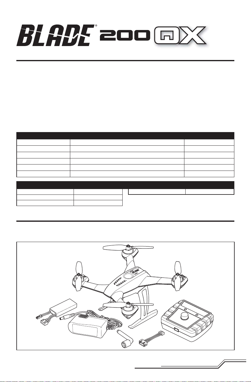
Table of Contents
First Flight Preparation .....................................................4
Flying Checklist ...............................................................4
Charging Warnings...........................................................4
Battery Charging ..............................................................5
Installing the Flight Battery ..............................................5
Transmitter and Receiver Binding .....................................6
SAFE Technology .............................................................6
Flight Mode and Rate Selection (RTF) ...............................6
Transmitter Setup Table ...................................................7
LED Codes .....................................................................10
Understanding the Primary Flight Controls .....................10
Flying the 200 QX ..........................................................11
Components BNF
Airframe
Motors
On-board Electronics
Battery
Charger
Transmitter
Length
Height
Propeller Diameter
Blade® 200 QX
20mm Brushless 3000Kv
4-in-1 mixer/ESCs/Gyro
2S 7.4V 20C 800mAh Li-Po Battery
2S Li-Po DC Charger with AC Power Supply
Full Range DSM2®/DSMX® Transmitter (DX4e and up)
Specifications
5.59 in (142mm)
3.54 in (90mm)
4.45 in (113mm)
Box Contents
• Blade 200 QX
• 2S 7.4V 20C 800mAh Li-Po Battery
• 2S Li-Po DC Charger with AC Power Supply
Post-Flight Inspection and Maintenance Checklist ..........11
Removing the Propellers ................................................11
Optional Camera Mount .................................................11
Troubleshooting Guide ...................................................12
Exploded View ...............................................................13
Parts Listings .................................................................13
Optional Parts ................................................................13
Limited Warranty ...........................................................14
Warranty and Service Contact Information .....................15
FCC Information .............................................................15
IC Information ...............................................................15
Compliance Information for the European Union .............15
Included
Installed
Installed
Included
Included
Required
Flying Weight
To register your product online,visit www.bladehelis.com
• Charger Adapter
• Propeller Nut Wrench
6.70 oz (190 g)
3
EN
Page 4

First Flight Preparation
• Remove and inspect contents
• Begin charging the fl ight battery
• Install the fl ight battery in the quadcopter
(once it has been fully charged)
• Program your computer transmitter
• Bind your transmitter
• Familiarize yourself with the controls
• Find a suitable area for fl ying
Charging Warnings
The Battery Charger (EFLUC1009) included with your quadcopter has been designed to safely charge the Li-Po battery.
CAUTION: All instructions and warnings must be
followed exactly. Mishandling of Li-Po batteries can
result in a fi re, personal injury and/or property damage.
• By handling, charging or using the included Li-Po battery,
you assume all risks associated with lithium batteries.
• If at any time the battery begins to balloon or swell,
discontinue use immediately. If charging or discharging,
discontinue and disconnect. Continuing to use, charge or
discharge a battery that is ballooning or swelling can result
in fi re.
• Always store the battery at room temperature in a dry area
for best results.
• Always transport or temporarily store the battery in a temperature range of 40–120º F (5–49° C). Do not store battery
or model in a car or direct sunlight. If stored in a hot car, the
battery can be damaged or even catch fi re.
• Always charge batteries away from fl ammable materials.
Flying Checklist
❏ Always turn the transmitter on fi rst
❏ Plug the fl ight battery into the lead from the
4-in-1 control unit
❏ Allow the 4-in-1 control unit to initialize and arm properly
❏ Fly the model
❏ Land the model
❏ Unplug the fl ight battery from the 4-in-1 control unit
❏ Always turn the transmitter off last
• Always inspect the battery before charging.
• Always disconnect the battery after charging, and let the
charger cool between charges.
• Always constantly monitor the temperature of the battery
pack while charging.
• ONLY USE A CHARGER SPECIFICALLY DESIGNED TO CHARGE
LI-PO BATTERIES. Failure to charge the battery with a
compatible charger may cause a fi re resulting in personal
injury and/or property damage.
• Never discharge Li-Po cells to below 3V under load.
• Never cover warning labels with hook and loop strips.
• Never leave charging batteries unattended.
• Never charge batteries outside recommended levels.
• Never charge damaged batteries.
• Never attempt to dismantle or alter the charger.
• Never allow minors to charge battery packs.
• Never charge batteries in extremely hot or cold places
(recommended between 40–120° F or 5–49° C) or place in
direct sunlight.
EN
4
Page 5
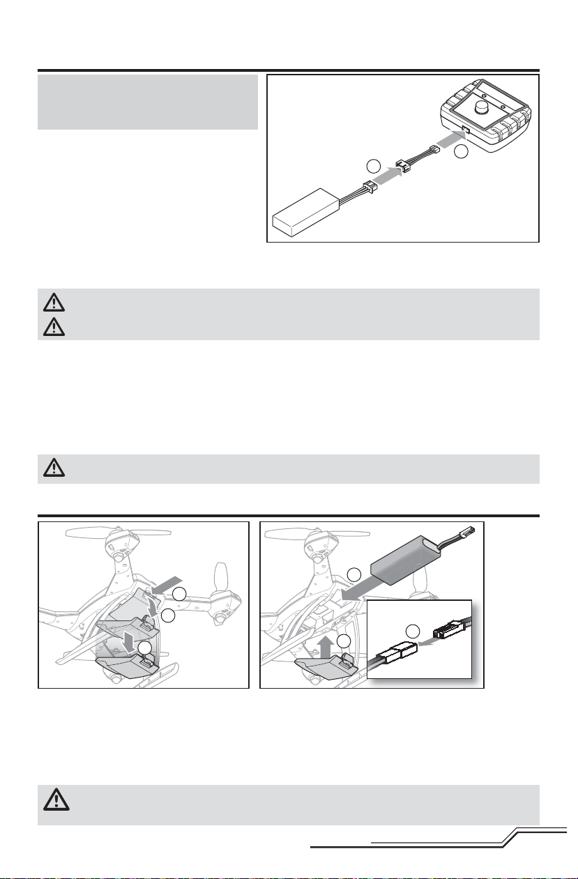
Battery Charging
NOTICE: Charge only batteries that are cool to the
touch and are not damaged. Look at the battery to
make sure it is not damaged e.g., swollen, bent,
broken or punctured.
1. Connect the AC power supply to the charger.
2. Connect the other end of the power supply to an
appropriate AC power source.
3. Connect the battery balance lead to the charger
adapter (A).
4. Connect the charger adapter to the charger (B).
5. Press the Start/Stop Button to begin charging.
6. Battery charging is complete when the charger
LED is solid green.
7. Always disconnect the fl ight battery from the charger immediately upon completion of charging.
Charging a fully discharged (not over-discharged) 800mAh battery takes approximately 60 minutes.
CAUTION: Only use chargers specifi cally designed to charge the included Li-Po battery. Failure to do so could
result in fi re, causing injury or property damage.
CAUTION: Never exceed the recommended charge rate.
LED Indications
Flashing Green LED with power connected but without battery: Standby
Flashing Green LED: Battery connected
Flashing Red LED at varying speeds: Charging
Simultaneously Flashing Red and Green LEDs: Balancing
Solid Green LED: Full Charge
Rapidly Flashing Red and Green LEDs: Error
CAUTION: Once charging is complete, immediately remove the battery.
Never leave a battery connected to the charger.
A
B
Installing the Flight Battery
D
A
B
C
1. Lower the throttle to the lowest setting.
2. Power on the transmitter.
3. Remove the battery cover (A-C) and install the battery in the quadcopter (D).
4. Connect the battery cable to the 4-in-1 control unit (E) and replace the battery cover (F).
5. Place the quadcopter on its landing gear on a fl at surface and leave it still until the LED on the 4-in-1 control unit
is solid (not blinking).
CAUTION: Always disconnect the Li-Po battery from the aircraft when not fl ying to avoid over-discharging the
battery. Batteries discharged to a voltage lower than the lowest approved voltage may become damaged,
resulting in loss of performance and potential fi re when batteries are charged.
F
E
5
EN
Page 6

™
Transmitter and Receiver Binding
To bind or re-bind your quadcopter to your chosen transmitter, please follow the directions below.
General Binding Procedure
1. Disconnect the fl ight battery from the quadcopter.
2. Select a clean model memory on your transmitter (computer radios only).
3. Select Acro or Airplane model type on your transmitter.
4. Make sure all servo reversing is set correctly for your radio. Refer to the Transmitter Setup Table.
5. Center all trims on your transmitter.
6. Power off the transmitter and move all switches to the 0 position. Move the throttle to the low/off position.
7. Connect the fl ight battery in the quadcopter. The blue LED on the 4-in-1 control unit fl ashes after 5 seconds.
8. Put the transmitter into bind mode while powering on the transmitter.
9. Release the bind button/switch after 2–3 seconds. The quadcopter is bound when the blue LED on the 4-in-1
control unit turns solid.
10. Disconnect the fl ight battery and power the transmitter off.
®
CAUTION: When using a Futaba
the throttle channel and re-bind. Refer to your Spektrum module manual for binding and failsafe instructions.
Refer to your Futaba transmitter manual for instructions on reversing the throttle channel.
If you encounter problems, obey binding instructions and refer to the troubleshooting guide for other instructions.
If needed, contact the appropriate Horizon Product Support offi ce. For a list of compatible DSM® transmitters,
please visit www.bindnfl y.com.
transmitter with a Spektrum™ DSM2®/DSMX® module, you must reverse
Technology
Revolutionary SAFE™ (Sensor Assisted Flight Envelope) technology uses an innovative combination of multi-axis sensors
and software that allows model aircraft to know its position relative to the horizon. This spatial awareness is utilized to
create a controlled fl ight envelope the aircraft can use to maintain a safe region of bank and pitch angles so you can fl y
more safely. Far beyond stability, this level of protection offers multiple modes so the pilot can choose to develop his or
her skills with a greater degree of security and fl ight control that always feels crisp and responsive.
SAFE technology delivers:
• Flight envelope protection you can enable at the fl ip of a switch.
• Multiple modes let you adapt SAFE technology to your skill level instantly.
Best of all, sophisticated SAFE technology doesn’t require any work to enjoy. Every aircraft with SAFE installed is ready to
use and optimized to offer the best possible fl ight experience.
FlySAFERC.com
Flight Mode and Rate Selection
• In stability low angle mode, the controls provide a minimum bank angle. This mode is shown by the fl ight control board
on the quadcopter glowing solid green.
• In stability high angle mode, the controls provide for a maximum bank angle. This mode is shown by the fl ight control
board on the quadcopter glowing solid blue.
• Agility mode is shown by the fl ight control board on the quadcopter glowing solid red.
Refer to the Transmitter Setup Table for which switch on your transmitter selects fl ight modes and specifi c setup information.
EN
6
Page 7

Transmitter Setup Table
Low
Rate
High
Rate
Rate
Switch
N/A
100%
Fixed
Rate
70%
Fixed
100%
Fixed
Rate
70%
Fixed
100%
Fixed
Rate
70%
Fixed
100%
Fixed
Rate
Camera Operation Dual
Still Mode(Default)
Press Left Stick = Take
Throttle Cut
Default = Stability Mode, Low
Mode Setup Switch Positions
Picture
Video Mode
Press Left Stick = Start/
Stop Recording
Press & Hold Left Stick
(4 Seconds) = Change
Modes
Still Mode(Default)
Press Trainer = Take
Lower throttle
trim until mo-
tors stop turning
Angle (Quad Solid Green LED)
Press Right Stick = Agility Mode
(Quad Solid Red LED)
Channel 5 (0) = Stability Mode,
Picture
Video Mode
Press Trainer = Start/Stop
Recording
Press & Hold Trainer for 4
Seconds = Change Modes
Lower throttle
trim until mo-
tors stop turning
Low Angle
Channel 5 (1) = Stability Mode,
High Angle
Channel 5 (2) = Agility Mode
Still Mode(Default)
Press Trainer = Take
Picture
Video Mode
Press Trainer = Start/Stop
Recording
Press & Hold Trainer for 4
Seconds = Change Modes
Still Mode(Default)
Lower throttle
trim until mo-
tors stop turning
ACT/AUX (OFF) = Stability Mode,
Low Angle
ACT/AUX (ON) = Agility Mode
Press Trainer = Take
Picture
Video Mode
Press Trainer = Start/Stop
Recording
Press & Hold Trainer for 4
Seconds = Change Modes
Lower throttle
trim until mo-
tors stop turning
Channel 5 (0) = Stability Mode,
Low Angle
Channel 5 (1) = Agility Mode
Reverse
Transmitter Model
Setup
Type
MLP4DSM N/A N/A N/A
MLP6DSM N/A N/A N/A
N/A N/A N/A
DX4e (Old)
w/ 2 Position
Switch
7
DX5e (Old)
N/A N/A N/A
w/ 2 Position
Switch
EN
Page 8

Low
Rate
High
Rate
Rate
Switch
70%
Fixed
100%
Fixed
Rate
70%
Fixed
ELEV-AIL
100% 70%
D/R
100%
Fixed
Rate
ELEV-AIL
100% 70%
D/R
Camera Operation Dual
Still Mode(Default)
Press Trainer = Take
Throttle Cut
Channel 5 (0) = Stability Mode,
Low Angle
Mode Setup Switch Positions
Picture
Video Mode
Press Trainer = Start/Stop
Lower throttle
trim until mo-
Channel 5 (1) = Stability Mode,
High Angle
Recording
Press & Hold Trainer for 4
Seconds = Change Modes
Still Mode(Default)
Press Trainer = Take
tors stop turning
Channel 5 (2) = Agility Mode
Channel 5 (0) = Stability Mode,
Picture
Lower throttle
Low Angle
Video Mode
Press Trainer = Start/Stop
Recording
Press & Hold Trainer for 4
trim until mo-
tors stop turning
Channel 5 (1) = Stability Mode,
High Angle
Still Mode(Default)
FLAP 0-1-0 = Take Picture
Video Mode
Seconds = Change Modes
GEAR (0); Mix (0) = Stability Mode,
Channel 5 (2) = Agility Mode
Setup List:
Throttle Cut – ACT
FLAP 0-1-0 = Start/Stop
Press throttle
cut
Low Angle
GEAR (1); Mix (0) = Stability Mode,
High Angle
MIX 1: ACT; Gear → Gear ACT
Travel Adj:
GEAR (0)↑ 100%; F MODE (1) ↓40%
FLAPS: Norm ←↑100; LAND ↓100
Recording
FLAP Pos 0-1(4 Sec-
onds)-0 = Change Modes
Still Mode(Default)
GEAR (1); Mix (1) = Agility Mode
GEAR (0); Mix (0) = Stability Mode,
RATE D 0%
U + 100%
SW MIX
TRIM INH
Travel Adj:
FLAP 0-1-0 = Take Picture
Video Mode
FLAP 0-1-0 = Start/Stop
Recording
FLAP Pos 0-1(4 Sec-
onds)-0 = Change Modes
Lower throttle
trim until mo-
tors stop turning
Low Angle
GEAR (1); Mix (0) = Stability Mode,
High Angle
GEAR (1); Mix (1) = Agility Mode
GEAR (0)↑ 100%; GEAR (1) ↑40%
MIX 1: FLAP → Gear OFF/ON
RATE → -50%
0%
SW: MIX
OFFSET: 0
EN
Reverse
Transmitter Model
Setup
Type
N/A N/A N/A
DX4e (New)
w/ 3 Position
Switch
N/A N/A N/A
DX5e (New)
w/ 3 Position
Switch
FLAP - R (6)
GEAR - R
All Others - N
DX6i Acro
All Others - N
DX7/7SE Acro
8
Page 9

Low
Rate
High
Rate
Rate
Switch
ELEV-AIL
100% 70%
D/R
ELEV-AIL
100% 70%
D/R
ELEV-AIL
100% 70%B (1) = Stability Mode, High Angle
D/R
Camera Operation Dual
Throttle Cut
F MODE (0), ELEV D/R (1) =
Mode Setup Switch Positions
Switch Select:
Trainer to Aux 1; F Mode to Gear
Still Mode(Default)
Press Trainer = Take
Picture
Video Mode
Switch to Mix 1
Stability Mode, Low Angle
F MODE (1), ELEV D/R (1) =
Set All Others to Inh
Throttle Cut:
MIX 1
Mixing:
Press Trainer = Start/Stop
Recording
Press & Hold Trainer for 4
Seconds = Change Modes
Stability Mode, High Angle
F MODE (1), ELEV D/R (0) =
Agility mode
MIX 1: GER > GER
RATE: 0%
-100%
OFFSET: 0%;
TRIM: Inh
Still Mode(Default)
Press Trainer = Take
Picture
Video Mode
Press Trainer = Start/Stop
Recording
Switch to Mix 1
F MODE (0) = Stability Mode,
Low Angle
F MODE (1) = Stability Mode,
High Angle
SW: Ele D/R
Switch Select:
Trainer to Aux 1
F Mode to Gear
All Others to Inh
Throttle Cut:
Press & Hold Trainer for 4
Seconds = Change Modes
Still Mode(Default)
Press Trainer = Take
Picture
Video Mode
Switch H
F MODE (2) = Agility Mode
B (0) = Stability Mode, Low Angle
MIX 1
Channel Assign: NEXT
1-4: N/A
5 Gear: B
6 AUX1: I
Press Trainer = Start/Stop
Recording
Press & Hold Trainer for 4
Seconds = Change Modes
B (2) = Agility Mode
7-10: Inh
Throttle Cut: Switch H
Reverse
Transmitter Model
Setup
Type
AUX1 - R
All Others - N
DX7S Acro
AUX1 - R
DX8 Acro
9
All Others - N
AUX1 - R
All Others - N
DX9/DX18 Acro
EN
Page 10

LED Codes
Equipment LED Color LED Status Operation
Blue
Green Solid Stability Mode low angle
Red Solid Agility Mode
Quadcopter
All LEDs
White Blink
Rapid Blink Bind Mode
Solid Stability Mode high angle
Slow Blink 7.1V Low Voltage Warning
Medium Blink 7.0V Low Voltage Warning
Rapid Blink 6.9V Low Voltage Warning
6.2V Low Voltage Cutoff:
Motors shut off
Understanding the Primary Flight Controls
If you are not familiar with the controls of your 200 QX, take a few minutes to familiarize yourself with them before
attempting your fi rst fl ight.
Throttle
Left Side View Left Side View
Descend
Throttle up
Rudder
Rudder left
Elevator
Elevator down
Aileron
Climb
Nose Yaws Left
Left Side View Left Side View
Forward
Throttle down
Rudder right
Elevator up
Nose Yaws Right
Backward
Rear ViewRear View
EN
Aileron left
Left
10
Aileron right
Right
Page 11

Flying the 200 QX
Takeo
When you are prepared to fl y, move both sticks into the bottom inside corners, then back to center. Increase the throttle
until the model is approximately 2 ft. (600mm) off the ground and check the trim so the model fl ies as desired. Once the
trim is adjusted, begin fl ying the model.
Typical fl ight times for the included battery range from 5 to 7 minutes.
Low Voltage Cuto (LVC)
LVC decreases the power to the motors when the battery voltage gets low. When the motor power decreases and the
LEDs blink, land the aircraft immediately and recharge the fl ight battery.
LVC does not prevent the battery from over-discharge during storage.
NOTICE: Repeated fl ying to LVC will damage the battery.
Landing
To land, slowly decrease the throttle while in a low-level hover. After landing, disconnect and remove the battery from
the aircraft after use to prevent trickle discharge. Fully charge your battery before storing it. During storage, make sure
the battery charge does not fall below 3V per cell.
Post-Flight Inspection and Maintenance Checklist
√
Cleaning
Motors Replace the motor when the model will not fl y steady or veers off when doing a climb out.
Wiring Make sure the wiring does not block moving parts. Replace damaged wiring and loose connectors.
Fasteners
Propellers
Removing the Propellers
Remove the propeller nuts using the included propeller
nut wrench according to the illustration. Install them in the
opposite direction. Turn the silver prop nuts clockwise to
tighten. Turn the gold prop nuts counterclockwise to tighten.
Optional Camera Mount
A Camera mounting points
B Camera / Software update port
Make sure the battery is not connected before cleaning. Remove dust and debris with a soft brush
or a dry, lint-free cloth.
Make sure there are no loose screws, other fasteners or connectors. Do not over-tighten metal
screws in plastic parts. Tighten screws so the parts are mated together, then turn the screw only
1/8th of a turn more.
Make sure there is no damage to the propellers or other parts that move at high speed. Damage to
these parts includes cracks, burrs, chips or scratches. Replace damaged parts before fl ying.
Removing the propeller nuts
Silver Gold
B
SilverGold
A
11
A
EN
Page 12

Troubleshooting Guide
Problem Possible Cause Solution
Quadcopter control response
is inconsistent or requires
extra trim to neutralize movement
Quadcopter will not respond
to throttle
Quadcopter does not function
and smells burnt after connecting the fl ight battery
Quadcopter has reduced fl ight
time or is underpowered
LED on receiver fl ashes rapidly
and aircraft will not respond to
transmitter (during binding)
LED on the receiver fl ashes
rapidly and the quadcopter will
not respond to the transmitter
(after binding)
Crashes immediately upon
lift-off
Aircraft not initialized on a level surface
Battery not correctly placed in
battery slot
Throttle too high and/or throttle trim
is too high
Quadcopter moved during initialization
Throttle channel is reversed
Flight battery connected with the
wrong polarity
Flight battery charge is low Completely recharge the fl ight battery
Inadequate power to fl ight battery
charger
Flight battery is damaged
Flight conditions might be too cold
Transmitter too near aircraft during
binding process
Bind switch or button was not held
while transmitter was powered on
Aircraft or transmitter is too close to
large metal object, wireless source or
another transmitter
Less than a 5-second wait between
fi rst powering on the transmitter and
connecting the fl ight battery to the
quadcopter
The quadcopter is bound to a different
model memory (ModelMatch™ transmitters only)
Flight battery or transmitter battery
charge is too low
Aircraft or transmitter is too close to
large metal object, wireless source or
another transmitter
Propellers in wrong locations or
incorrect fl ight mode selected
Aileron, elevator or rudder are reversed
in the transmitter
Disconnect the fl ight battery, center the
control trim and re-initialize the quadcopter
Adjust battery position so quadcopter balances in the center of the frame
Reset controls with the throttle stick
and throttle trim at the lowest setting
Disconnect the flight battery and reinitialize the quadcopter while keeping the
quadcopter from moving
Disconnect fl ight battery, reverse the
throttle channel on the transmitter,
recconnect fl ight battery
Replace the 4-in-1 board. Connect the
fl ight battery noting proper polarity
Use a different power source for the
charger
Replace the fl ight battery and follow the
fl ight battery instructions
Make sure the battery is warm (room temperature) before use
Power off the transmitter. Move the transmitter a larger distance from the aircraft.
Disconnect and reconnect the fl ight battery
to the aircraft. Follow the binding instructions
Power off transmitter and repeat bind
process
Move aircraft and transmitter to another
location and attempt binding again
Leave the transmitter powered on. Disconnect and reconnect the fl ight battery to the
quadcopter
Select the correct model memory on the
transmitter. Disconnect and reconnect the
fl ight battery to the quadcopter
Replace or recharge batteries
Move aircraft and transmitter to another
location and attempt connecting again
Ensure propeller direction and motor
direction are correct
Ensure aileron, elevator or rudder are not
reversed
EN
12
Page 13

Exploded View
7
8
10
6
9
1
2
10
5
Parts Listings
Part # Description
1 BLH7701 Main Control Board: 200 QX
2 BLH7702 Landing Gear: 200 QX
3 BLH7703 Red LEDs: 200 QX
4 BLH7704 Green LEDs: 200 QX
5 BLH7705
6 BLH7706
7 BLH7707 Gray Propellers: 200 QX
8 BLH7708 Red Propellers: 200 QX
Brushless Motor CW Rotation,
3000 Kv: 200 QX
Brushless Motor CCW Rotation,
3000 Kv: 200 QX
5
4
12
2
Part # Description
9 BLH7709 4-in-1 ESC: 200 QX
10 BLH7710 Body Set: 200 QX
11 BLH7711 Screw Set: 200 QX, not shown
12 BLH7712 Battery Cover: 200 QX
13 EFLB8002SJ 2S 7.4V 20C 800mAh Li-Po Battery
14 EFLUC1009
EFLC4001/
15
AUS/1EU/UK
2S 800mA Li-Po DC Charger,
not shown
12V 500mAh Power Supply (Based
upon your sales region), not shown
6
13
Optional Parts
Part # Description
EFLB8002SJ30 2S 7.4V 30C 800mAh Li-Po Battery
EFLC3025/AU/
EU/UK
Celectra 80W AC/DC Multi-Chemistry Battery
Charger (Based upon your sales region)
DX4e DSMX 4-Channel Transmitter Only
DX5e DSMX 5-Channel Transmitter Only
Part # Description
DX6i DSMX 6-Channel Transmitter Only
DX7 DSMX 7-Channel Transmitter Only
DX8 DSMX 8-Channel Transmitter Only
DX9 DSMX 9-Channel Transmitter Only
DX18 DSMX 18-Channel Transmitter Only
13
EN
Page 14

Limited Warranty
What this Warranty Covers
Horizon Hobby, LLC (Horizon) warrants to the original purchaser
that the product purchased (the "Product") will be free from
defects in materials and workmanship at the date of purchase.
What is Not Covered
This warranty is not transferable and does not cover (i) cosmetic
damage, (ii) damage due to acts of God, accident, misuse,
abuse, negligence, commercial use, or due to improper use,
installation, operation or maintenance, (iii) modification of or to
any part of the Product, (iv) attempted service by anyone other
than a Horizon Hobby authorized service center, (v) Product not
purchased from an authorized Horizon dealer, or (vi) Product not
compliant with applicable technical regulations.
OTHER THAN THE EXPRESS WARRANTY ABOVE, HORIZON
MAKES NO OTHER WARRANTY OR REPRESENTATION, AND
HEREBY DISCLAIMS ANY AND ALL IMPLIED WARRANTIES,
INCLUDING, WITHOUT LIMITATION, THE IMPLIED WARRANTIES
OF NON-INFRINGEMENT, MERCHANTABILITY AND FITNESS FOR
A PARTICULAR PURPOSE. THE PURCHASER ACKNOWLEDGES
THAT THEY ALONE HAVE DETERMINED THAT THE PRODUCT
WILL SUITABLY MEET THE REQUIREMENTS OF THE
PURCHASER’S INTENDED USE.
Purchaser’s Remedy
Horizon’s sole obligation and purchaser’s sole and exclusive
remedy shall be that Horizon will, at its option, either (i) service,
or (ii) replace, any Product determined by Horizon to be defective. Horizon reserves the right to inspect any and all Product(s)
involved in a warranty claim. Service or replacement decisions
are at the sole discretion of Horizon. Proof of purchase is
required for all warranty claims. SERVICE OR REPLACEMENT
AS PROVIDED UNDER THIS WARRANTY IS THE PURCHASER’S
SOLE AND EXCLUSIVE REMEDY.
Limitation of Liability
HORIZON SHALL NOT BE LIABLE FOR SPECIAL, INDIRECT,
INCIDENTAL OR CONSEQUENTIAL DAMAGES, LOSS OF
PROFITS OR PRODUCTION OR COMMERCIAL LOSS IN ANY
WAY, REGARDLESS OF WHETHER SUCH CLAIM IS BASED IN
CONTRACT, WARRANTY, TORT, NEGLIGENCE, STRICT LIABILITY
OR ANY OTHER THEORY OF LIABILITY, EVEN IF HORIZON HAS
BEEN ADVISED OF THE POSSIBILITY OF SUCH DAMAGES.
Further, in no event shall the liability of Horizon exceed the
individual price of the Product on which liability is asserted. As
Horizon has no control over use, setup, final assembly, modification or misuse, no liability shall be assumed nor accepted
for any resulting damage or injury. By the act of use, setup or
assembly, the user accepts all resulting liability. If you as the
purchaser or user are not prepared to accept the liability associated with the use of the Product, purchaser is advised to return
the Product immediately in new and unused condition to the
place of purchase.
Law
These terms are governed by Illinois law (without regard to
conflict of law principals). This warranty gives you specific legal
rights, and you may also have other rights which vary from state
to state. Horizon reserves the right to change or modify this
warranty at any time without notice.
WARRANTY SERVICES
Questions, Assistance, and Services
Your local hobby store and/or place of purchase cannot provide
warranty support or service. Once assembly, setup or use of the
Product has been started, you must contact your local distributor
or Horizon directly. This will enable Horizon to better answer your
questions and service you in the event that you may need any
assistance. For questions or assistance, please visit our website
at www.horizonhobby.com, submit a Product Support Inquiry, or
call the toll free telephone number referenced in the Warranty
and Service Contact Information section to speak with a Product
Support representative.
Inspection or Services
If this Product needs to be inspected or serviced and is compliant in the country you live and use the Product in, please use
the Horizon Online Service Request submission process found
on our website or call Horizon to obtain a Return Merchandise
Authorization (RMA) number. Pack the Product securely
using a shipping carton. Please note that original boxes may
be included, but are not designed to withstand the rigors of
shipping without additional protection. Ship via a carrier that
provides tracking and insurance for lost or damaged parcels, as
Horizon is not responsible for merchandise until it arrives and is
accepted at our facility. An Online Service Request is available at
http://www.horizonhobby.com/content/_service-center_renderservice-center. If you do not have internet access, please contact
Horizon Product Support to obtain a RMA number along with
instructions for submitting your product for service. When calling
Horizon, you will be asked to provide your complete name, street
address, email address and phone number where you can be
reached during business hours. When sending product into
Horizon, please include your RMA number, a list of the included
items, and a brief summary of the problem. A copy of your
original sales receipt must be included for warranty consideration. Be sure your name, address, and RMA number are clearly
written on the outside of the shipping carton.
NOTICE: Do not ship LiPo batteries to Horizon. If you have
any issue with a LiPo battery, please contact the appropriate Horizon Product Support office.
Warranty Requirements
For Warranty consideration, you must include your origi-
nal sales receipt verifying the proof-of-purchase date.
Provided warranty conditions have been met, your Product will
be serviced or replaced free of charge. Service or replacement
decisions are at the sole discretion of Horizon.
Non-Warranty Service
Should your service not be covered by warranty, service
will be completed and payment will be required without notification or estimate of the expense unless the
expense exceeds 50% of the retail purchase cost. By sub-
mitting the item for service you are agreeing to payment of the
service without notification. Service estimates are available upon
request. You must include this request with your item submitted
for service. Non-warranty service estimates will be billed a minimum of ½ hour of labor. In addition you will be billed for return
freight. Horizon accepts money orders and cashier’s checks, as
well as Visa, MasterCard, American Express, and Discover cards.
By submitting any item to Horizon for service, you are agreeing
to Horizon’s Terms and Conditions found on our website http://
www.horizonhobby.com/content/_service-center_renderservice-center.
ATTENTION: Horizon service is limited to Product compliant in the country of use and ownership. If received,
a non-compliant Product will not be serviced. Further,
the sender will be responsible for arranging return shipment of the un-serviced Product, through a carrier of the
sender’s choice and at the sender’s expense. Horizon will
hold non-compliant Product for a period of 60 days from
notification, after which it will be discarded.
EN
14
Page 15

Warranty and Service Contact Information
Country of
Purchase
United States of
America
United Kingdom
Germany
France
China
Horizon Hobby Contact Information Address
Horizon Service Center
(Repairs and Repair Requests)
Horizon Product Support
(Product Technical Assistance)
Sales
Service/Parts/Sales:
Horizon Hobby Limited
Horizon Technischer Service service@horizonhobby.de
Sales: Horizon Hobby GmbH +49 (0) 4121 2655 100
Service/Parts/Sales:
Horizon Hobby SAS
Service/Parts/Sales:
Horizon Hobby – China
servicecenter.horizonhobby.
com/RequestForm/
www.quickbase.com/db/
bghj7ey8c?a=GenNewRecord
888-959-2304
sales@horizonhobby.com
888-959-2304
sales@horizonhobby.co.uk
+44 (0) 1279 641 097
infofrance@horizonhobby.com
+33 (0) 1 60 18 34 90
info@horizonhobby.com.cn
+86 (021) 5180 9868
Compliance Information for the European Union
Declaration of Conformity
(in accordance with ISO/IEC 17050-1)
No. HH2014051101
Product(s): BLH 200 QX BL BNF
Item Number(s): BLH7780EU / BLH7780UK
Equipment class: 1
The object of declaration described above is in conformity
with the requirements of the specifi cations listed below,
following the provisions of the European R&TTE directive
1999/5/EC, EMC Directive 2004/108/EC and LVD Directive
2006/95/EC:
EN 301 489-1 V1.9.2: 2012
EN 301 489-17 V2.1.1: 2009
EN60950-1:2006+A11:2009+A1:2010+A12: 2011
EN61000-3-2:2006+A1:2009+A2:2009
EN61000-3-3:2008
EN55022:2010 + AC:2011
EN55024:2010
Instructions for disposal of WEEE by users
to a designated collections point for the recycling of waste
electrical and electronic equipment. The separate collection
and recycling of your waste equipment at the time of disposal
will help to conserve natural resources and make sure that it
is recycled in a manner that protects human health and the
environment. For more information about where you can drop
off your waste equipment for recycling, please contact your
local city offi ce, your household waste disposal service or
where you purchased the product.
4105 Fieldstone Rd
Champaign, Illinois, 61822 USA
Units 1–4 , Ployters Rd, Staple Tye
Harlow, Essex, CM18 7NS, United
Kingdom
Christian-Junge-Straße 1
25337 Elmshorn, Germany
11 Rue Georges Charpak
77127 Lieusaint, France
Room 506, No. 97 Changshou Rd.
Shanghai, China 200060
in the European Union
This product must not be disposed of with other
waste. Instead, it is the user’s responsibility to dispose of their waste equipment by handing it over
Signed for and on behalf of:
Horizon Hobby, LLC.
Champaign, IL USA
May 11, 2014
Robert Peak
Chief Financial Offi cer
Horizon Hobby, LLC
15
EN
Page 16

©2014 Horizon Hobby, LLC.
Blade, E-fl ite, SAFE, the SAFE logo, DSM, DSM2, DSMX, the BNF logo, ModelMatch, Celectra
and the Horizon Hobby logo are trademarks or registered trademarks of Horizon Hobby, LLC.
The Spektrum trademark is used with permission of Bachmann Industries, Inc. Futaba is a registered trademark of Futaba Denshi
Kogyo Kabushiki Kaisha Corporation of Japan. All other trademarks, service marks or logos are property of their respective owners.
Patents pending. Created 5/14 43513.1 BLH7780
IT
60
 Loading...