

BLADE BLH7400A, BLH7480A User manual

Instruction Manual
Bedienungsanleitung
Manuel d’utilisation
Manuale di Istruzioni
RTF
READY-TO-FLY

NOTICE
All instructions, warranties and other collateral documents are subject to change at the sole discretion of Horizon
Hobby, Inc. For up-to-date product literature, visit horizonhobby.com and click on the support tab for this product.
Meaning of Special Language
The following terms are used throughout the product literature to indicate various levels of potential harm when
operating this product:
NOTICE: Procedures, which if not properly followed, create a possibility of physical property damage AND a little or no
possibility of injury.
CAUTION: Procedures, which if not properly followed, create the probability of physical property damage AND a
possibility of serious injury.
WARNING: Procedures, which if not properly followed, create the probability of property damage, collateral damage,
and serious injury OR create a high probability of superfi cial injury.
WARNING: Read the ENTIRE instruction manual to become familiar with the features of the product before
operating. Failure to operate the product correctly can result in damage to the product, personal property and
cause serious injury.
This is a sophisticated hobby product. It must be operated with caution and common sense and requires some basic
mechanical ability. Failure to operate this Product in a safe and responsible manner could result in injury or damage
to the product or other property. This product is not intended for use by children without direct adult supervision. Do
not use with incompatible components or alter this product in any way outside of the instructions provided by Horizon
Hobby, Inc. This manual contains instructions for safety, operation and maintenance. It is essential to read and follow
all the instructions and warnings in the manual, prior to assembly, setup or use, in order to operate correctly and avoid
damage or serious injury.
Age Recommendation: Not for children under 14 years. This is not a toy.
Safety Precautions and Warnings
• Always keep a safe distance in all directions around
your model to avoid collisions or injury. This model is
controlled by a radio signal subject to interference from
many sources outside your control. Interference can
cause momentary loss of control.
• Always operate your model in open spaces away from
full-size vehicles, traffi c and people.
• Always carefully follow the directions and warnings for
this and any optional support equipment
(chargers, rechargeable battery packs, etc.).
• Always keep all chemicals, small parts and anything
electrical out of the reach of children.
• Always avoid water exposure to all equipment not
specifi cally designed and protected for this purpose.
Moisture causes damage to electronics.
• Never place any portion of the model in your mouth as it
could cause serious injury or even death.
• Never operate your model with low transmitter
batteries.
• Always keep aircraft in sight and under control.
• Always move the throttle fully down at rotor strike.
• Always use fully charged batteries.
• Always keep transmitter powered on while aircraft is
powered.
• Always remove batteries before disassembly
• Always keep moving parts clean.
• Always keep parts dry.
• Always let parts cool after use before touching.
• Always remove batteries after use.
• Never operate aircraft with damaged wiring.
• Never touch moving parts.
EN
2
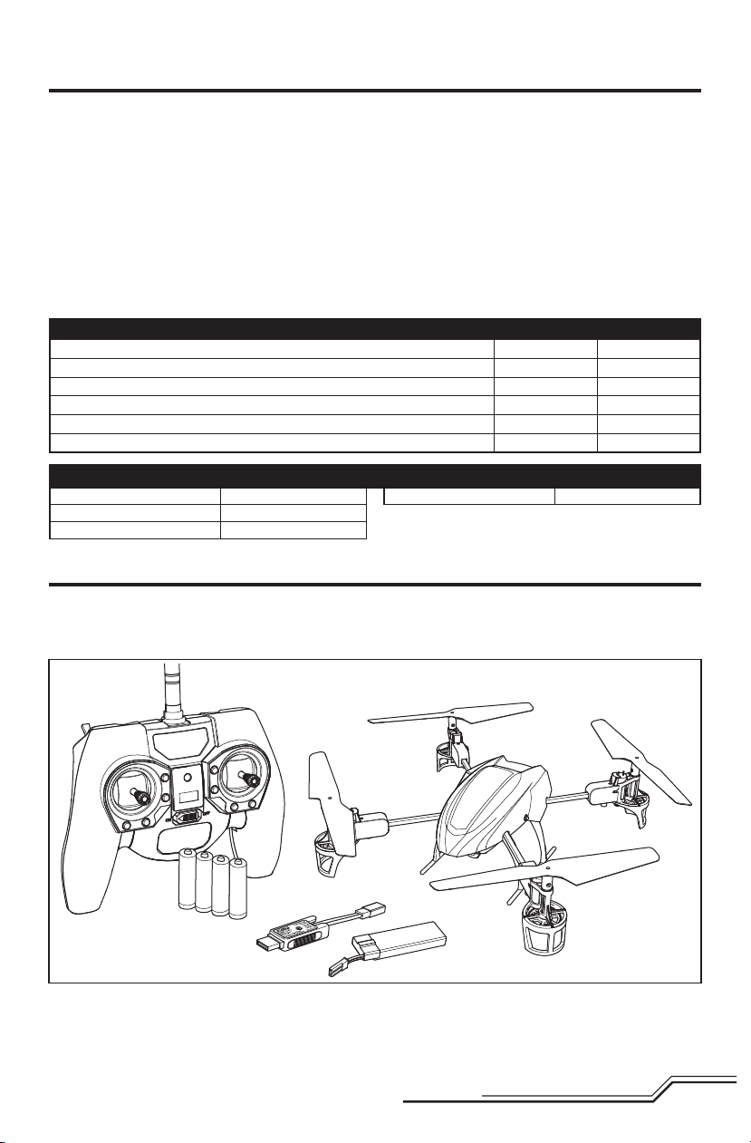
Table of Contents
First Flight Preparation .....................................................4
Flying Checklist ...............................................................4
Charging Warnings...........................................................4
Installing the Landing Gear ..............................................5
Installing the Transmitter Batteries (RTF) ..........................5
Installing the Flight Battery ..............................................5
Transmitter and Receiver Binding .....................................6
SAFE Technology .............................................................7
Transmitter Control ..........................................................7
Flight Mode and Rate Selection (RTF) ...............................8
Transmitter Setup Table ...................................................9
LED Codes .....................................................................12
Understanding the Primary Flight Controls .....................12
Blade 180 QX HD Features RTF BNF
Airframe – Blade® 180 QX HD Included Included
Motors – 8.5mm Brushed Installed Installed
On-board Electronics – 5-in-1 mixer/ESCs/Gyro Installed Installed
Battery – 500mAh 1S 3.7V 25C Li-Po Included Included
Charger – 1S USB Li-Po Charger, 500 mAh, JST Included Included
Transmitter – MLP6DSM SAFE™ Transmitter Included Required
Blade 180 QX HD Specifications
Length
Height
Propeller Diameter
13.98 in (355mm)
3.15 in (80mm)
5.35 in (136mm)
Flying the 180 QX HD .....................................................13
Post-Flight Inspection and Maintenance Checklist ..........13
Operating the Camera ...................................................13
Troubleshooting Guide ...................................................15
Exploded View ...............................................................16
Parts Listings .................................................................16
Optional Parts ................................................................16
Limited Warranty ...........................................................17
Warranty and Service Contact Information .....................18
FCC Information .............................................................18
IC Information ...............................................................18
Compliance Information for the European Union .............19
Flying Weight
To register your product online,visit www.bladehelis.com
3.35 oz (95 g)
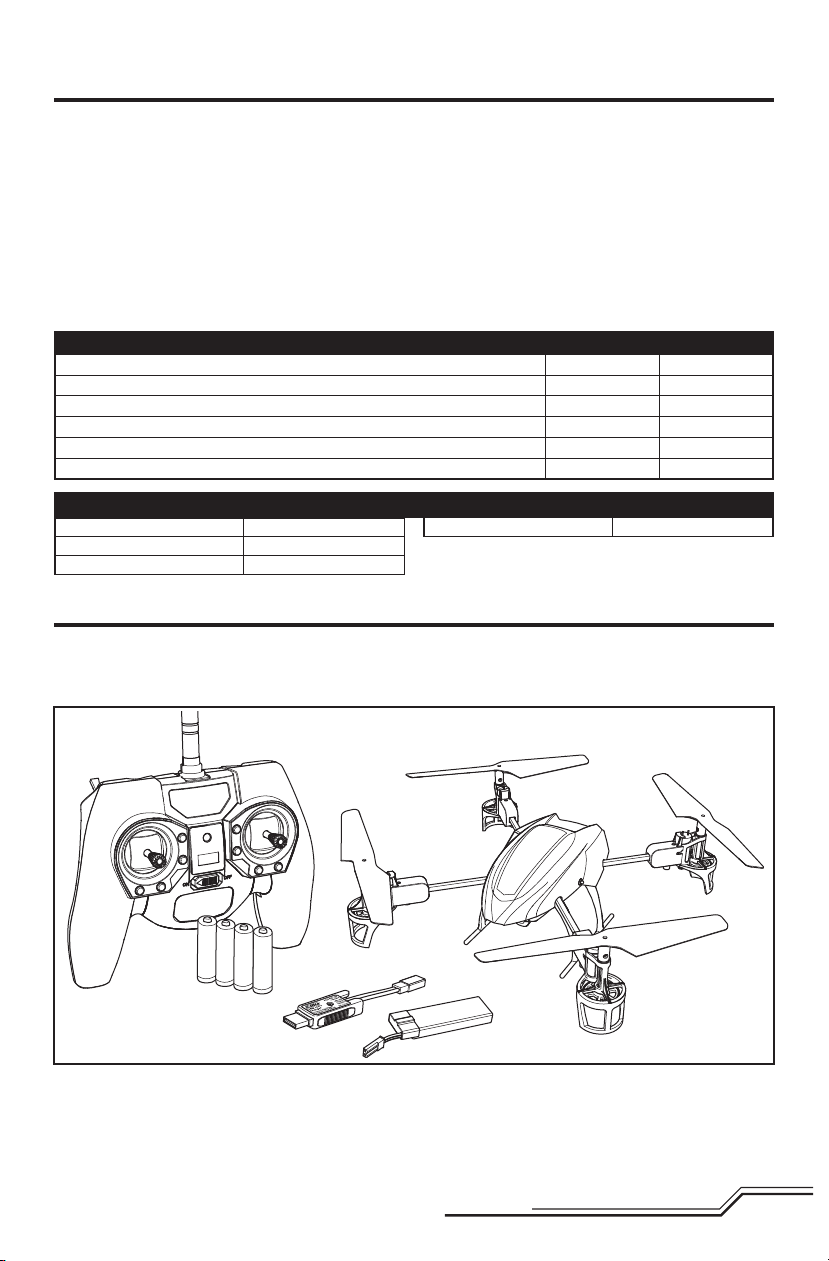
Box Contents
• Blade 180 QX HD
• 720p Digital Video Camera with Still Capability
• 1S 3.7V 25C 500mAh Li-Po Battery
• 1S USB Li-Po Charger
• MLP6DSM SAFE Transmitter (RTF Only)
• 4 AA Batteries (RTF Only)
3
EN
First Flight Preparation
• Remove and inspect contents
• Begin charging the fl ight battery
• Install the fl ight battery in the quadcopter
(once it has been fully charged)
• Program your computer transmitter (BNF only)
• Bind your transmitter (BNF only)
• Familiarize yourself with the controls
• Find a suitable area for fl ying
Charging Warnings
The Battery Charger (EFLC1010) included with your
quadcopter has been designed to safely charge the Li-Po
battery.
CAUTION: All instructions and warnings must be
followed exactly. Mishandling of Li-Po batteries can
result in a fi re, personal injury and/or property damage.
• By handling, charging or using the included Li-Po battery,
you assume all risks associated with lithium batteries.
• If at any time the battery begins to balloon or swell,
discontinue use immediately. If charging or discharging,
discontinue and disconnect. Continuing to use, charge or
discharge a battery that is ballooning or swelling can result
in fi re.
• Always store the battery at room temperature in a dry area
for best results.
• Always transport or temporarily store the battery in a temperature range of 40–120º F (5–49° C). Do not store battery
or model in a car or direct sunlight. If stored in a hot car, the
battery can be damaged or even catch fi re.
Flying Checklist
❏ Always turn the transmitter on fi rst
❏ Plug the fl ight battery into the lead from the 5-in-1
control unit
❏ Allow the 5-in-1 control unit to initialize and arm
properly
❏ Fly the model
❏ Land the model
❏ Unplug the fl ight battery from the 5-in-1 control unit
❏ Always turn the transmitter off last
• Always charge batteries away from fl ammable materials.
• Always inspect the battery before charging
• Always disconnect the battery after charging, and let the
charger cool between charges.
• Always constantly monitor the temperature of the battery
pack while charging.
• ONLY USE A CHARGER SPECIFICALLY DESIGNED TO CHARGE
LI-PO BATTERIES. Failure to charge the battery with a
compatible charger may cause a fi re resulting in personal
injury and/or property damage.
• Never discharge Li-Po cells to below 3V under load.
• Never cover warning labels with hook and loop strips.
• Never leave charging batteries unattended.
• Never charge batteries outside recommended levels.
• Never charge damaged batteries.
• Never attempt to dismantle or alter the charger.
• Never allow minors to charge battery packs.
• Never charge batteries in extremely hot or cold places
(recommended between 40–120° F or 5–49° C) or place in
direct sunlight.
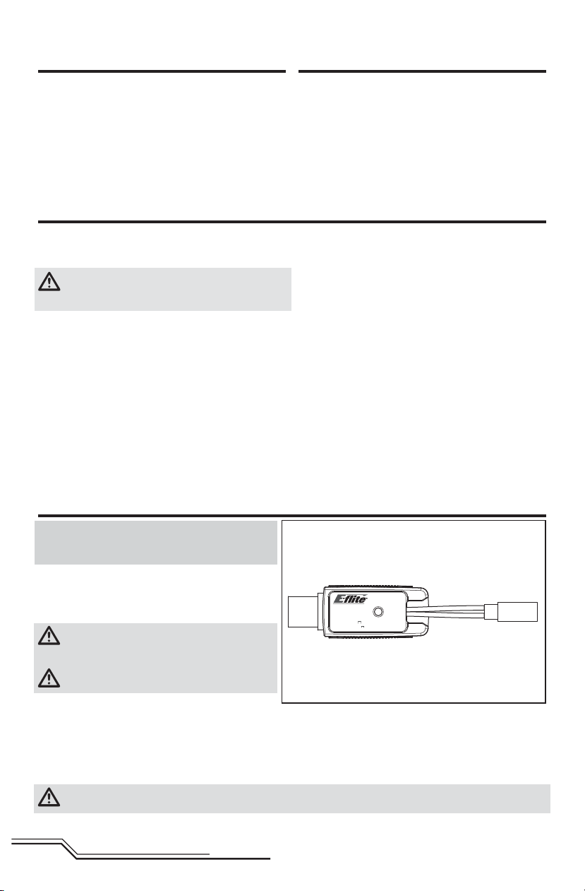
Battery Charging
NOTICE: Charge only batteries that are cool to the touch
and are not damaged. Look at the battery to make sure it
is not damaged e.g., swollen, bent, broken or punctured.
1. Insert the charger into a USB port.
2. Properly connect the battery to the charger lead.
3. Always disconnect the fl ight battery from the charger
immediately upon completion of charging.
CAUTION: Only use chargers specifi cally designed
to charge the included Li-Po battery. Failure to do
so could result in fi re, causing injury or property damage.
CAUTION: Never exceed the recommended charge
rate.
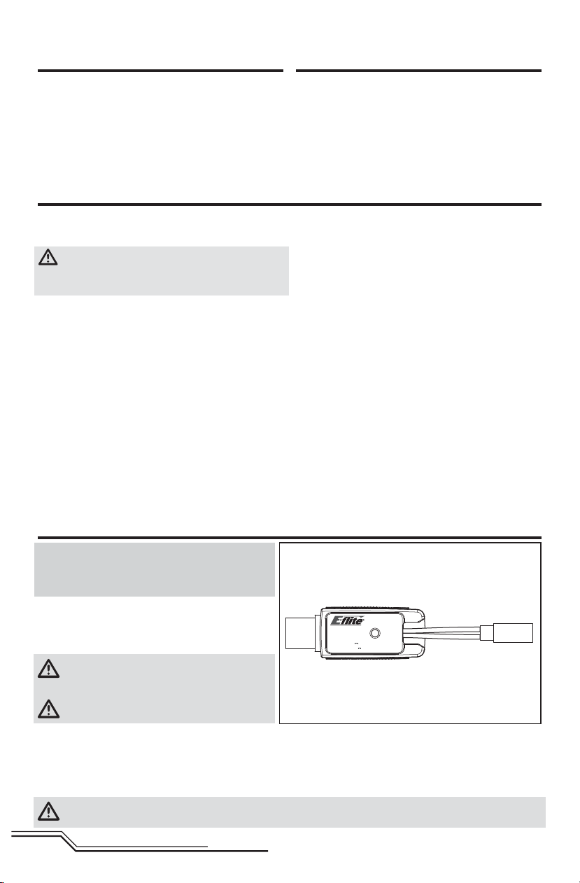
LED Indications
When you make the connection successfully, the LED on the charger turns solid red, indicating charging has begun.
Charging a fully discharged (not over-discharged) 500mAh battery takes approximately 60 minutes. The light goes out
when the charge is complete.
CHARGING (Solid Red)
MAX CHARGE (OFF)
CAUTION: Once charging is complete, immediately remove the battery. Never leave a battery connected to the
charger.
EN
4
USB Li-Po
Charger
DC Input:5.0V 500mA
DC Output:4.2V 500mA
SOLID RED LED
–Charging
LED OFF
–Charge
Complete
EFLC1010
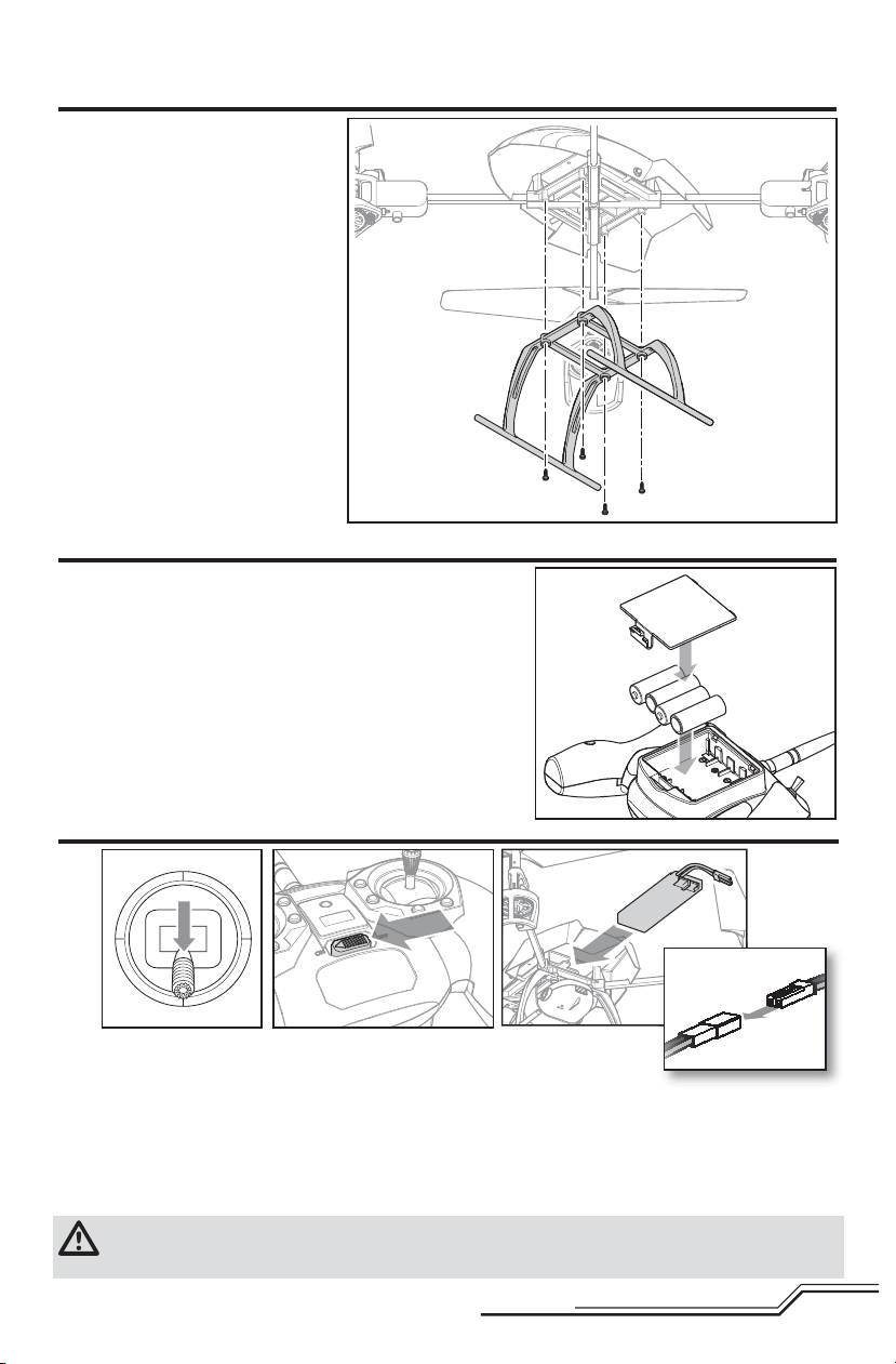
Installing the Landing Gear
Install the landing gear using the
four included screws.
Installing the Transmitter Batteries (RTF)
Replace the transmitter batteries when the power LED fl ashes and the
transmitter beeps.
Installing the Flight Battery
12
1. Lower the throttle and throttle trim to the lowest settings.
2. Power on the transmitter.
3. Install the battery by sliding it into the battery mounting slot below the 5-in-1 control unit. Slide the battery into the
slots with the label facing upward so that the battery key molded into the battery end-cap comes in contact with
the key on the battery slot.
4. Connect the battery cable to the 5-in-1 control unit.
5. Place the quadcopter on its skids on a fl at surface and leave the aircraft still until the LED on the 5-in-1 control unit
is solid blue (not blinking)
CAUTION: Always disconnect the Li-Po battery from the aircraft when not fl ying to avoid over-discharging the
battery. Batteries discharged to a voltage lower than the lowest approved voltage may become damaged,
resulting in loss of performance and potential fi re when batteries are charged.
3
4
5
EN
Transmitter and Receiver Binding
To bind or re-bind your quadcopter to your chosen transmitter, please follow the directions below.
General Binding Procedure
1. Disconnect the fl ight battery from the quadcopter.
2. Select a clean model memory on your transmitter (computer radios only).
3. Select Acro or Airplane model type on your transmitter.
4. Make sure all servo reversing is set to Normal on your transmitter.
5. Center all trims on your transmitter.
6. Power off the transmitter and move all switches to the 0 position. Move the throttle to the low/off position.
7. Connect the fl ight battery in the quadcopter. The blue LED on the 5-in-1 control unit fl ashes after 5 seconds.
8. Put the transmitter into bind mode while powering on the transmitter.
9. Release the bind button/switch after 2–3 seconds. The quadcopter is bound when the blue LED on the
5-in-1 control unit turns solid.
10. Disconnect the fl ight battery and power the transmitter off.
CAUTION: When using a Futaba® transmitter with a Spektrum™ DSM2®/DSMX® module, you must reverse the
throttle channel and re-bind. Refer to your Spektrum module manual for binding and failsafe instructions.
Refer to your Futaba transmitter manual for instructions on reversing the throttle channel.
RTF
Your RTF transmitter comes prebound to the model. If you need to re-bind, follow the directions below.
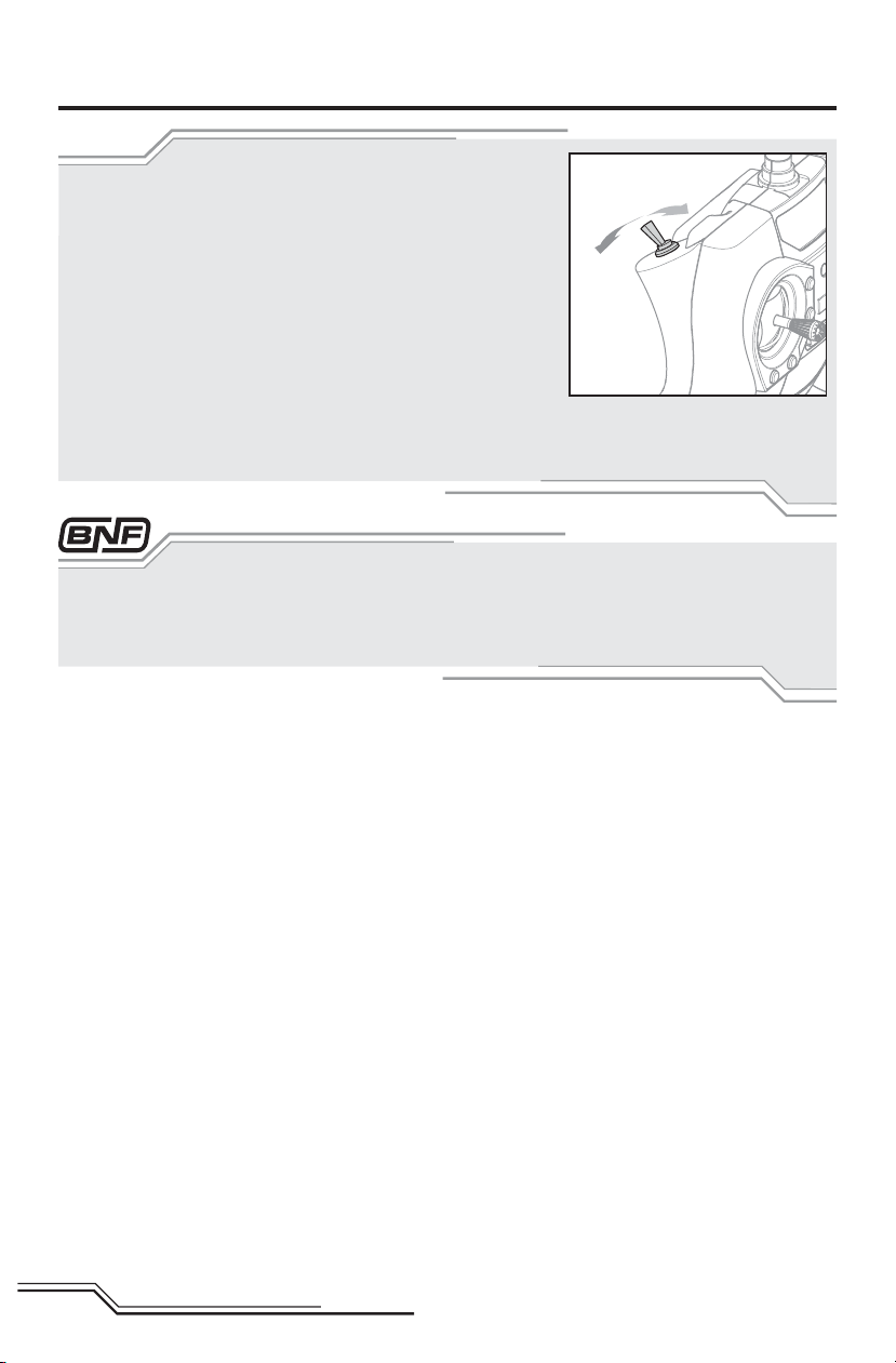
MLP6DSM Binding Procedure
1. Disconnect the fl ight battery from the quadcopter.
2. Center all trims on your transmitter.
3. Power off the transmitter and move the throttle stick to the down/off position.
4. Connect the fl ight battery in the quadcopter. The LED on the 5-in-1 control unit fl ashes after 5 seconds.
5. When the blue light is fl ashing, push in and hold down the left stick* while powering on the transmitter
(you will hear a ‘click’).
6. Release the left stick. The transmitter will beep and the power LED will blink.
7. The quadcopter is bound when the LED on the 5-in-1 control unit is solid blue (not blinking).
8. Disconnect the fl ight battery and power the transmitter off.
* The trigger switch may also be used for the binding procedure.
If you encounter problems, obey binding instructions and refer to the troubleshooting guide for other instructions.
If needed, contact the appropriate Horizon Product Support offi ce. For a list of compatible DSM
visit www.bindnfl y.com.
EN
6
®
transmitters, please
Technology
™
a
(b
Revolutionary SAFE™ (Sensor Assisted Flight Envelope) technology uses an innovative combination of multi-axis sensors
and software that allows model aircraft to know its position relative to the horizon. This spatial awareness is utilized to create
a controlled fl ight envelope the aircraft can use to maintain a safe region of bank and pitch angles so you can fl y more safely.
Far beyond stability, this level of protection offers multiple modes so the pilot can choose to develop his or her skills with a
greater degree of security and fl ight control that always feels crisp and responsive.
SAFE technology delivers:
• Flight envelope protection you can enable at the fl ip of a switch.
• Multiple modes let you adapt SAFE technology to your skill level instantly.
Best of all, sophisticated SAFE technology doesn’t require any work to enjoy. Every aircraft with SAFE installed is ready to use
and optimized to offer the best possible fl ight experience.
FlySAFERC.com
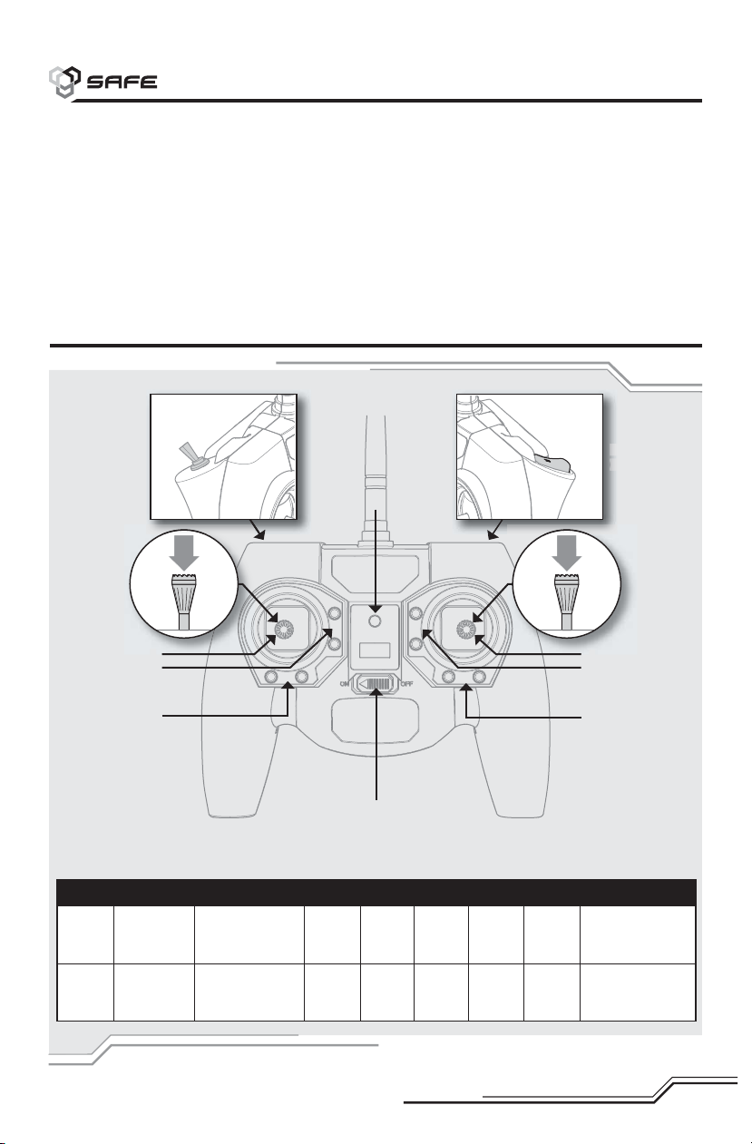
Transmitter Control
RTF
C
Flight mode
switch
A
Camera trigger
(bind switch)
Bind switch
H
G
F
E
Dual rate
switch
B
C
D
When pressed down, trim buttons make a sound that increases or decreases in pitch at each pressing. The middle or
neutral trim position is heard as a middle tone in the pitch range of the sounds. The end of the control range is sounded
by a series of beeps.
H ABCDEFGH
Mode 1 Power LED/
fl ight mode
Aileron (Left/Right)
Throttle (Up/Down)
Throttle
Trim
Aileron
Trim
ON/OFF
Switch
Rudder
Trim
Elevator Trim
Rudder (Left/Right)
Elevator (Up/Down)
indicator
Mode 2 Power LED/
fl ight mode
indicator
Aileron (Left/Right)
Elevator (Up/
Down)
Elevator Trim
Aileron
Trim
7
ON/OFF
Switch
Rudder
Trim
Throttle
Trim
Rudder (Left/Right)
Throttle (Up/Down)
EN
Flight Mode and Rate Selection
RTF
Change fl ight modes by moving the three-position fl ight mode switch. Ensure
the fl ight mode switch is in the desired position before fl ying.
• In stability low angle mode (switch position 0), the controls provide a
minimum bank angle. This mode is shown by the fl ight control board on
the quadcopter glowing solid blue.
• In stability high angle mode (switch position 1), the controls provide for a
maximum bank angle. This mode is shown by the fl ight control board on
the quadcopter slowly fl ashing blue.
• Agility mode (switch position 2) is shown by the fl ight control board on
the quadcopter glowing solid red.
When powered on, this transmitter is automatically in high-rate mode.
Change rates by pressing and releasing the right control stick.
• In low-rate mode, the controls cannot reach their maximum values.
• In high-rate mode, the controls can reach their maximum values.
If you purchased a BNF 180 QX HD, the channel 5 switch on your transmitter will select fl ight modes. When the LED on
the control board is solid blue, the fl ight mode is set to stability low angle mode. When the LED is slowly blinking blue,
the quadcopter is in stability high angle mode. When the light is solid red, the quadcopter is in agility mode. See the
Transmitter Setup Table for specifi c setup information.
EN
8

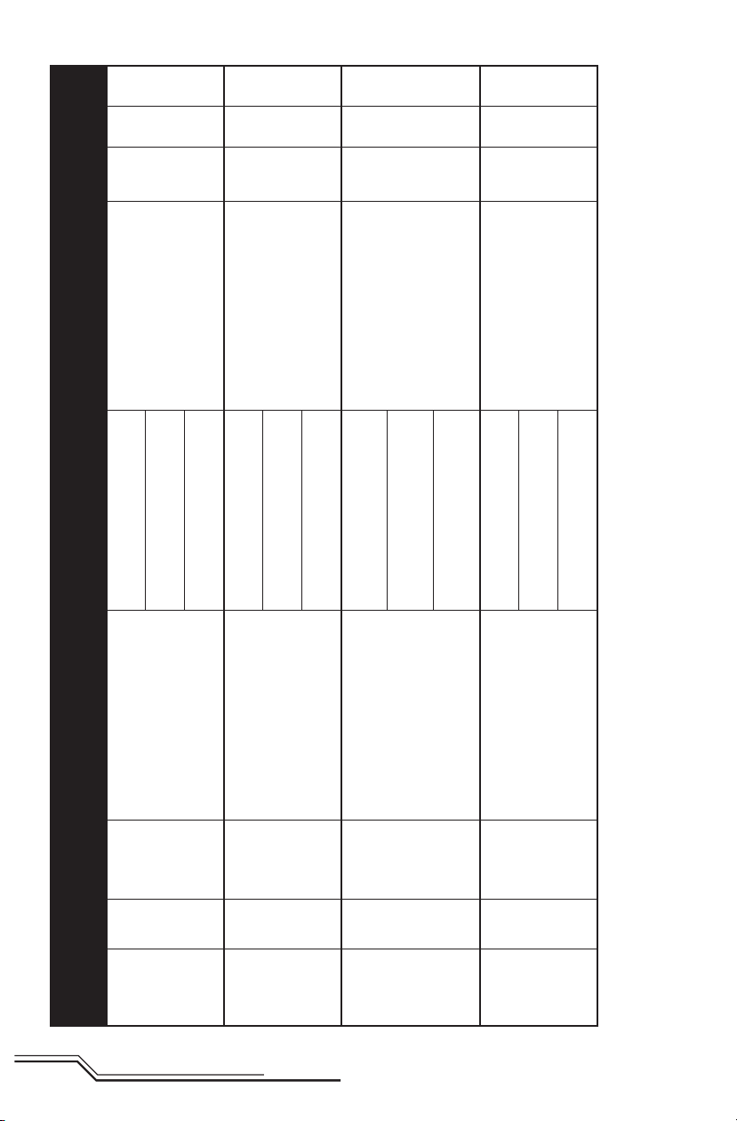
Transmitter Setup Table
Low
Rate
High
Rate
Rate
Switch
N/A
100%
Fixed
Rate
Still Mode(Default)
Press Left Stick = Take Picture
Video Mode
Press Left Stick = Start/Stop Recording
Press & Hold Left Stick (4 Seconds) =
Change Modes
70%
Fixed
100%
Fixed
Rate
Still Mode(Default)
Press Trainer = Take Picture
Video Mode
Press Trainer = Start/Stop Recording
Press & Hold Trainer for 4 Seconds =
Change Modes
70%
Fixed
100%
Fixed
Rate
Still Mode(Default)
Press Trainer = Take Picture
Video Mode
Press Trainer = Start/Stop Recording
Press & Hold Trainer for 4 Seconds =
Change Modes
70%
Fixed
100%
Fixed
Rate
Still Mode(Default)
Press Trainer = Take Picture
Video Mode
Press Trainer = Start/Stop Recording
Press & Hold Trainer for 4 Seconds =
Change Modes
Mode Setup Switch Positions Camera Operation Dual
Reverse
Transmitter Model
Setup
Type
Default = Stability Mode, Low Angle
(Quad Solid Blue LED)
Press Right Stick = Agility Mode
(Quad Solid Red LED)
MLP4DSM N/A N/A N/A
Channel 5 (0) = Stability Mode,
Low Angle
Channel 5 (1) = Stability Mode,
High Angle
Channel 5 (2) = Agility Mode
ACT/AUX (OFF) = Stability Mode,
MLP6DSM N/A N/A N/A
9
Low Angle
N/A N/A N/A
DX4e (Old)
w/ 2 Position
ACT/AUX (ON) = Agility Mode
Switch
Channel 5 (0) = Stability Mode,
Low Angle
Channel 5 (1) = Agility Mode
N/A N/A N/A
DX5e (Old)
w/ 2 Position
Switch
EN
Low
Rate
High
Rate
Rate
Switch
Still Mode(Default)
Channel 5 (0) = Stability Mode, Low
70%
Fixed
100%
Fixed
Rate
Press Trainer = Take Picture
Video Mode
Press Trainer = Start/Stop Recording
Press & Hold Trainer for 4 Seconds =
Change Modes
Angle
Channel 5 (1) = Stability Mode, High
Angle
Channel 5 (2) = Agility Mode
Still Mode(Default)
Channel 5 (0) = Stability Mode, Low
70%
Fixed
100%
Fixed
Rate
Press Trainer = Take Picture
Video Mode
Press Trainer = Start/Stop Recording
Press & Hold Trainer for 4 Seconds =
Change Modes
Angle
Channel 5 (1) = Stability Mode, High
Angle
Channel 5 (2) = Agility Mode
100% 70%
ELEV-AIL
D/R
Still Mode(Default)
FLAP 0-1-0 = Take Picture
Video Mode
FLAP 0-1-0 = Start/Stop Recording
FLAP Pos 0-1(4 Seconds)-0 = Change
Modes
Still Mode(Default)
GEAR (0); Mix (0) = Stability Mode,
Low Angle
GEAR (1); Mix (0) = Stability Mode,
High Angle
GEAR (1); Mix (1) = Agility Mode
GEAR (0); Mix (0) = Stability Mode,
Low Angle
100% 70%
ELEV-AIL
D/R
FLAP 0-1-0 = Take Picture
Video Mode
FLAP 0-1-0 = Start/Stop Recording
FLAP Pos 0-1(4 Seconds)-0 = Change
Modes
GEAR (1); Mix (0) = Stability Mode,
High Angle
GEAR (1); Mix (1) = Agility Mode
EN
Mode Setup Switch Positions Camera Operation Dual
Reverse
Transmitter Model
Setup
Type
N/A N/A N/A
DX4e (New)
w/ 3 Position
Switch
N/A N/A N/A
DX5e (New)
w/ 3 Position
Switch
Travel Adj:
GEAR (0)↑ 100%; F MODE (1) ↓40%
10
FLAPS: Norm ←↑100; LAND ↓100
MIX 1: ACT; Gear → Gear ACT
GEAR - R
RATE D 0%
U + 100%
SW MIX
All Others - N
DX6i Acro
TRIM INH
Travel Adj:
GEAR (0)↑ 100%; GEAR (1) ↑40%
MIX 1: FLAP → Gear OFF/ON
RATE → -50%
0%
FLAP - R (6)
All Others - N
DX7/7SE Acro
SW: MIX
OFFSET: 0
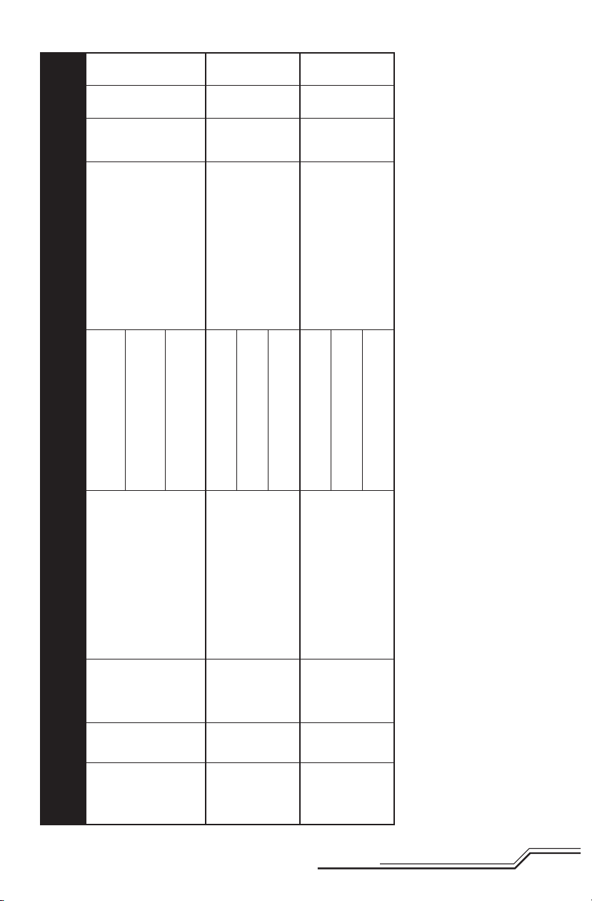
Low
Rate
High
Rate
Rate
Switch
F MODE (0) = Stability Mode,
100% 70%
ELEV-AIL
D/R
Still Mode(Default)
Press Trainer = Take Picture
Video Mode
Press Trainer = Start/Stop Recording
Press & Hold Trainer for 4 Seconds =
Change Modes
Low Angle
F MODE (1) = Stability Mode,
High Angle
F MODE (1); HOLD (1) = Agility Mode
100% 70%
ELEV-AIL
D/R
Still Mode(Default)
Press Trainer = Take Picture
Video Mode
Press Trainer = Start/Stop Recording
Press & Hold Trainer for 4 Seconds =
Change Modes
Still Mode(Default)
F MODE (0) = Stability Mode,
Low Angle
F MODE (1) = Stability Mode,
High Angle
F MODE (2) = Agility Mode
B (0) = Stability Mode, Low Angle
100% 70%B (1) = Stability Mode, High Angle
ELEV-AIL
D/R
Press Trainer = Take Picture
Video Mode
Press Trainer = Start/Stop Recording
Press & Hold Trainer for 4 Seconds =
Change Modes
B (2) = Agility Mode
Mode Setup Switch Positions Camera Operation Dual
Reverse
Transmitter Model
Setup
Type
Switch Select:
Trainer to Aux 1; F Mode to Gear
Set All Others to Inh
MIX 1: GER > GER
RATE: 0%
-100%
AUX1 - R
All Others - N
DX7S Acro
OFFSET: 0%;
TRIM: Inh
SW: Mix0
Switch Select:
Trainer to Aux 1
F Mode to Gear
All Others to Inh
AUX1 - R
All Others - N
DX8 Acro
Channel Assign: NEXT
1-4: N/A
5 Gear: B
6 AUX1: I
7-10: Inh
AUX1 - R
All Others - N
DX9/DX18 Acro
11
EN

LED Codes
Equipment LED Color LED Status Operation
Rapid Blink Bind Mode
Blue
Quadcopter
RTF Transmitter Red
Red Solid Agility Mode
Red and Blue
Solid Stability Mode low angle
Slow Blink Stability Mode high angle
Solid Low Battery
Blink Loss of RF/TX Off
Blink Low Rate
Solid Hi Rate
Understanding the Primary Flight Controls
If you are not familiar with the controls of your 180 QX HD, take a few minutes to familiarize yourself with them before
attempting your fi rst fl ight.
Throttle
Left Side View Left Side View
Descend
Throttle up
Rudder
Rudder left
Elevator
Aileron
Climb
Nose Yaws Left
Left Side View Left Side View
ForwardElevator down
Throttle down
Rudder right
Elevator up
Nose Yaws Right
Backward
Rear ViewRear View
EN
Aileron left
Left
12
Aileron right
Right
Flying the 180 QX HD
Takeo
Increase the throttle until the model is approximately 2 ft. (600mm) off the ground and check the trim so the model
fl ies as desired. Once the trim is adjusted, begin fl ying the model.
Typical fl ight times for the included battery range from 5 to 10 minutes.
Low Voltage Cuto (LVC)
LVC decreases the power to the motors when the battery voltage gets low. When the motor power decreases and the
blue and red LEDs on the 5-in-1 unit are solid, land the aircraft immediately and recharge the fl ight battery.
LVC does not prevent the battery from over-discharge during storage.
NOTICE: Repeated fl ying to LVC will damage the battery.
Landing
To land, slowly decrease the throttle while in a low-level hover. After landing, disconnect and remove the battery from
the aircraft after use to prevent trickle discharge. Fully charge your battery before storing it. During storage, make sure
the battery charge does not fall below 3V per cell.
Post-Flight Inspection and Maintenance Checklist
√
Cleaning
Motors Replace the motor when the model will not fl y steady or veers off when doing a climb out.
Wiring Make sure the wiring does not block moving parts. Replace damaged wiring and loose connectors.
Fasteners
Propellers
Operating the Camera
Charging
1. Connect the included USB cable to the USB port on a
compatible power source.
2. Connect the other end of the USB cable to the camera.
3. The red LED will glow solid.
4. When charging is complete, the red LED will turn off
and the blue LED will glow solid.
5. Disconnect the USB cable from the USB power source
and the camera.
When the camera battery is low, the red LED will blink.
Make sure the battery is not connected before cleaning. Remove dust and debris with a soft brush or
a dry, lint-free cloth.
Make sure there are no loose screws, other fasteners or connectors. Do not over-tighten metal
screws in plastic parts. Tighten screws so the parts are mated together, then turn the screw only
1/8th of a turn more.
Make sure there is no damage to the propellers or other parts that move at high speed. Damage to
these parts includes cracks, burrs, chips or scratches. Replace damaged parts before fl ying.
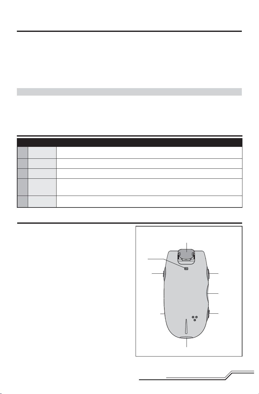
Positionable lense
LED
Power
button
Micro USB
port
Start/Stop
button
Micro SD
card slot
Mode
button
13
Servo lead port
EN
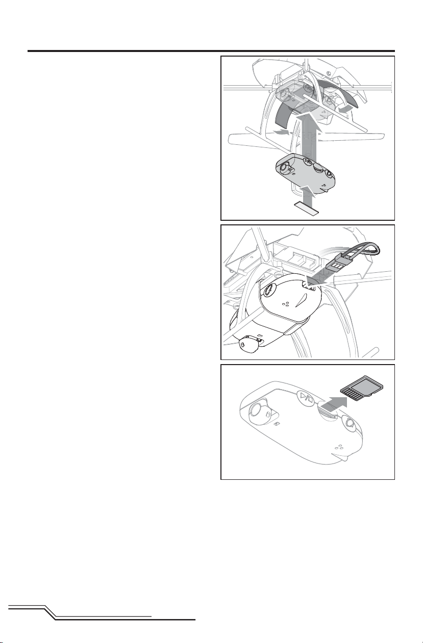
Installation
1. Install the included hook and loop tape on the bottom of
the camera, as shown.
2. Install the camera on the model using the included hook
and loop strap.
3. Connect the servo lead from the main board to the
camera servo lead port.
4. Press the camera power button. The red LED will glow
solid during initialization, then turn off. The blue LED will
glow solid.
Changing Modes
The camera comes from the factory in still mode. To
change between video and still mode, press and hold the
trigger. When changing to video mode, the blue LED will
blink twice. When changing back to still mode, the blue
LED will blink once.
Operation
To use the camera, press and release the trigger on the
back of the RTF transmitter. This will take a picture or start
recording video. Press the trigger again to stop recording
video. When taking a picture, the blue LED will blink once
and return to solid. When recording video, the blue LED will
blink slowly and return to solid when fi nished recording.
BNF Transmitters
To use the camera function with other transmitters, assign
channel 6 to a momentary switch/button on your transmitter. The switch/button will function the same as the RTF
trigger.
The camera also functions manually through the buttons.
Data Retrieval
Data from the camera can be retrieved through the micro
USB port or the removable 2GB TF micro SD card.
EN
14

Troubleshooting Guide
Problem Possible Cause Solution
Quadcopter control response
is inconsistent or requires
extra trim to neutralize movement.
Quadcopter will not respond
to throttle.
Quadcopter does not function
and smells burnt after connecting the fl ight battery.
Quadcopter has reduced fl ight
time or is underpowered.
LED on receiver fl ashes rapidly
and aircraft will not respond to
transmitter (during binding).
LED on the receiver fl ashes
rapidly and the quadcopter will
not respond to the transmitter
(after binding).
Crashes immediately upon
lift-off
Aircraft not initialized on a level surface.
Battery not correctly placed in
battery slot.
Throttle too high and/or throttle trim
is too high.
Quadcopter moved during initialization.
Throttle channel is reversed.
Flight battery connected with the
wrong polarity.
Flight battery charge is low. Completely recharge the fl ight battery.
Inadequate power to fl ight battery
charger.
Flight battery is damaged.
Flight conditions might be too cold.
Transmitter too near aircraft during
binding process.
Bind switch or button was not held
while transmitter was powered on.
Aircraft or transmitter is too close to
large metal object, wireless source or
another transmitter.
Less than a 5-second wait between
fi rst powering on the transmitter and
connecting the fl ight battery to the
quadcopter.
The quadcopter is bound to a different
model memory (ModelMatch™ transmitters only).
Flight battery or transmitter battery
charge is too low.
Aircraft or transmitter is too close to
large metal object, wireless source or
another transmitter.
Propellers in wrong locations or
incorrect fl ight mode selected.
Disconnect the fl ight battery, center the
control trim and re-initialize the quadcopter.
Adjust battery position so quadcopter balances in the center of the frame.
Reset controls with the throttle stick
and throttle trim at the lowest setting.
Disconnect the flight battery and reinitialize the quadcopter while keeping the
quadcopter from moving.
Disconnect fl ight battery, reverse the
throttle channel on the transmitter,
recconnect fl ight battery.
Replace the 5-in-1 board. Connect the
fl ight battery noting proper polarity.
Use a different USB power source for the
charger.
Replace the fl ight battery and follow the
fl ight battery instructions.
Make sure the battery is warm (room temperature) before use.
Power off the transmitter. Move the transmitter a larger distance from the aircraft.
Disconnect and reconnect the fl ight battery
to the aircraft. Follow the binding instructions.
Power off transmitter and repeat bind
process.
Move aircraft and transmitter to another
location and attempt binding again.
Leave the transmitter powered on. Disconnect and reconnect the fl ight battery to the
quadcopter.
Select the correct model memory on the
transmitter. Disconnect and reconnect the
fl ight battery to the quadcopter.
Replace or recharge batteries.
Move aircraft and transmitter to another
location and attempt connecting again.
Ensure propeller direction and motor
direction are correct.
15
EN
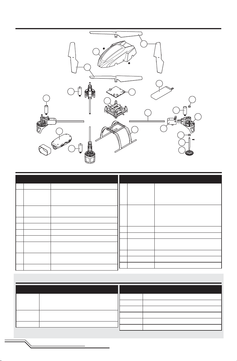
Exploded View
8
12
4
11
16
9
5
3
2
7
8
13
15
9
Parts Listings
Part # Description
1 BLH3506 Main Gear: BMSR/X, mCP X, mQX
BLH3515,
2
EFLH2215
3 BLH7401
4 BLH7402 Canopy: 180 QX HD
5 BLH7403 5-in-1 Mounting Frame: 180 QX HD
6 BLH7404 Landing Gear 180 QX HD
7 BLH7502 Thruster Boom with Wiring (2): mQX
8 BLH7503
9 BLH7504
10 BLH7513 Propeller Shaft, Carbon: mQX
Outer Shaft Bearing 3 x 6 x 2mm(2):
BMCX/2/MSR/X, FHX, MH-35, MCP
X, mQX
5-in-1 Control Unit, RX/ESCs/Mixer/
Gyros/Camera Control: 180 QX HD
Motor with Pinion, Clockwise Rotation:
mQX
Motor with Pinion, Counterclockwise
Rotation: mQX
Optional Parts
Part # Description
BLH7407
EFLC3025/
AU/EU/UK
Propellers, CW & CCW Rotation, White (2):
180 QX HD, mQX, 1 Propeller, White (CW),
1 Propeller, White (CCW), 2 Screws
Celectra 80W AC/DC Multi-Chemistry Battery
Charger (Based upon your sales region)
DX4e DSMX 4-Channel Transmitter Only
6
Part # Description
11 BLH7405
12 BLH7406
13 BLH7561 Motor Mount with Landing Skid: mQX
14 BLH7562 Motor Mount Cover (2): mQX
15 EFLA800
16 EFLB5001S25 500mAh 1S 3.7V 25C LiPo Battery
EFLC1010 1S USB Li-Po Charger, 500mA JST
EFLH1063 MLP6DSM SAFE Transmitter
Part # Description
14
2
10
1
Propellers, CW & CCW Rotation, Orange
(2): 180 QX HD, mQX, 1 Propeller,
Orange (CW), 1 Propeller,
Orange (CCW), 2 Screws
Propellers, CW & CCW Rotation, Black
(2): 180 QX HD, mQX, 1 Propeller,
Black (CW), 1 Propeller, Black (CCW),
2 Screws
Digital Video Camera With
Still Capability
DX5e DSMX 5-Channel Transmitter Only
DX6i DSMX 6-Channel Transmitter Only
DX7 DSMX 7-Channel Transmitter Only
DX8 DSMX 8-Channel Transmitter Only
DX9 DSMX 9-Channel Transmitter Only
DX18 DSMX 18-Channel Transmitter Only
EN
16

Limited Warranty
What this Warranty Covers
Horizon Hobby, Inc., (Horizon) warrants to the original purchaser
that the product purchased (the "Product") will be free from
defects in materials and workmanship at the date of purchase.
What is Not Covered
This warranty is not transferable and does not cover (i) cosmetic
damage, (ii) damage due to acts of God, accident, misuse,
abuse, negligence, commercial use, or due to improper use,
installation, operation or maintenance, (iii) modification of or to
any part of the Product, (iv) attempted service by anyone other
than a Horizon Hobby authorized service center, (v) Product not
purchased from an authorized Horizon dealer, or (vi) Product not
compliant with applicable technical regulations.
OTHER THAN THE EXPRESS WARRANTY ABOVE, HORIZON
MAKES NO OTHER WARRANTY OR REPRESENTATION, AND
HEREBY DISCLAIMS ANY AND ALL IMPLIED WARRANTIES,
INCLUDING, WITHOUT LIMITATION, THE IMPLIED WARRANTIES
OF NON-INFRINGEMENT, MERCHANTABILITY AND FITNESS FOR
A PARTICULAR PURPOSE. THE PURCHASER ACKNOWLEDGES
THAT THEY ALONE HAVE DETERMINED THAT THE PRODUCT
WILL SUITABLY MEET THE REQUIREMENTS OF THE
PURCHASER’S INTENDED USE.
Purchaser’s Remedy
Horizon’s sole obligation and purchaser’s sole and exclusive
remedy shall be that Horizon will, at its option, either (i) service,
or (ii) replace, any Product determined by Horizon to be defective. Horizon reserves the right to inspect any and all Product(s)
involved in a warranty claim. Service or replacement decisions
are at the sole discretion of Horizon. Proof of purchase is
required for all warranty claims. SERVICE OR REPLACEMENT
AS PROVIDED UNDER THIS WARRANTY IS THE PURCHASER’S
SOLE AND EXCLUSIVE REMEDY.
Limitation of Liability
HORIZON SHALL NOT BE LIABLE FOR SPECIAL, INDIRECT,
INCIDENTAL OR CONSEQUENTIAL DAMAGES, LOSS OF
PROFITS OR PRODUCTION OR COMMERCIAL LOSS IN ANY
WAY, REGARDLESS OF WHETHER SUCH CLAIM IS BASED IN
CONTRACT, WARRANTY, TORT, NEGLIGENCE, STRICT LIABILITY
OR ANY OTHER THEORY OF LIABILITY, EVEN IF HORIZON HAS
BEEN ADVISED OF THE POSSIBILITY OF SUCH DAMAGES.
Further, in no event shall the liability of Horizon exceed the
individual price of the Product on which liability is asserted. As
Horizon has no control over use, setup, final assembly, modification or misuse, no liability shall be assumed nor accepted
for any resulting damage or injury. By the act of use, setup or
assembly, the user accepts all resulting liability. If you as the
purchaser or user are not prepared to accept the liability associated with the use of the Product, purchaser is advised to return
the Product immediately in new and unused condition to the
place of purchase.
Law
These terms are governed by Illinois law (without regard to
conflict of law principals). This warranty gives you specific legal
rights, and you may also have other rights which vary from state
to state. Horizon reserves the right to change or modify this
warranty at any time without notice.
WARRANTY SERVICES
Questions, Assistance, and Services
Your local hobby store and/or place of purchase cannot provide
warranty support or service. Once assembly, setup or use of the
Product has been started, you must contact your local distributor
or Horizon directly. This will enable Horizon to better answer your
questions and service you in the event that you may need any
assistance. For questions or assistance, please visit our website
at www.horizonhobby.com, submit a Product Support Inquiry, or
call the toll free telephone number referenced in the Warranty
and Service Contact Information section to speak with a Product
Support representative.
Inspection or Services
If this Product needs to be inspected or serviced and is compliant in the country you live and use the Product in, please use
the Horizon Online Service Request submission process found
on our website or call Horizon to obtain a Return Merchandise
Authorization (RMA) number. Pack the Product securely
using a shipping carton. Please note that original boxes may
be included, but are not designed to withstand the rigors of
shipping without additional protection. Ship via a carrier that
provides tracking and insurance for lost or damaged parcels, as
Horizon is not responsible for merchandise until it arrives and is
accepted at our facility. An Online Service Request is available at
http://www.horizonhobby.com/content/_service-center_renderservice-center. If you do not have internet access, please contact
Horizon Product Support to obtain a RMA number along with
instructions for submitting your product for service. When calling
Horizon, you will be asked to provide your complete name, street
address, email address and phone number where you can be
reached during business hours. When sending product into
Horizon, please include your RMA number, a list of the included
items, and a brief summary of the problem. A copy of your
original sales receipt must be included for warranty consideration. Be sure your name, address, and RMA number are clearly
written on the outside of the shipping carton.
NOTICE: Do not ship LiPo batteries to Horizon. If you have
any issue with a LiPo battery, please contact the appropriate Horizon Product Support office.
Warranty Requirements
For Warranty consideration, you must include your origi-
nal sales receipt verifying the proof-of-purchase date.
Provided warranty conditions have been met, your Product will
be serviced or replaced free of charge. Service or replacement
decisions are at the sole discretion of Horizon.
Non-Warranty Service
Should your service not be covered by warranty, service
will be completed and payment will be required without notification or estimate of the expense unless the
expense exceeds 50% of the retail purchase cost. By sub-
mitting the item for service you are agreeing to payment of the
service without notification. Service estimates are available upon
request. You must include this request with your item submitted
for service. Non-warranty service estimates will be billed a minimum of ½ hour of labor. In addition you will be billed for return
freight. Horizon accepts money orders and cashier’s checks, as
well as Visa, MasterCard, American Express, and Discover cards.
By submitting any item to Horizon for service, you are agreeing
to Horizon’s Terms and Conditions found on our website http://
www.horizonhobby.com/content/_service-center_renderservice-center.
ATTENTION: Horizon service is limited to Product compliant in the country of use and ownership. If received,
a non-compliant Product will not be serviced. Further,
the sender will be responsible for arranging return shipment of the un-serviced Product, through a carrier of the
sender’s choice and at the sender’s expense. Horizon will
hold non-compliant Product for a period of 60 days from
notification, after which it will be discarded.
17
EN
Warranty and Service Contact Information
Country of
Purchase
United States of
America
United Kingdom
Germany
France
China
Horizon Hobby Contact Information Address
Horizon Service Center
(Repairs and Repair Requests)
Horizon Product Support
(Product Technical Assistance)
Sales
Service/Parts/Sales:
Horizon Hobby Limited
Horizon Technischer Service service@horizonhobby.de
Sales: Horizon Hobby GmbH +49 (0) 4121 2655 100
Service/Parts/Sales:
Horizon Hobby SAS
Service/Parts/Sales:
Horizon Hobby – China
servicecenter.horizonhobby.
com/RequestForm/
www.quickbase.com/db/
bghj7ey8c?a=GenNewRecord
888-959-2304
sales@horizonhobby.com
888-959-2304
sales@horizonhobby.co.uk
+44 (0) 1279 641 097
infofrance@horizonhobby.com
+33 (0) 1 60 18 34 90
info@horizonhobby.com.cn
+86 (021) 5180 9868
4105 Fieldstone Rd
Champaign, Illinois, 61822 USA
Units 1–4 , Ployters Rd, Staple Tye
Harlow, Essex, CM18 7NS, United
Kingdom
Christian-Junge-Straße 1
25337 Elmshorn, Germany
11 Rue Georges Charpak
77127 Lieusaint, France
Room 506, No. 97 Changshou Rd.
Shanghai, China 200060
FCC Information
This device complies with part 15 of the FCC rules. Operation is subject to the following two conditions: (1) This device
may not cause harmful interference, and (2) this device must accept any interference received, including interference that
may cause undesired operation.
CAUTION: Changes or modifi cations not expressly approved by the party responsible for compliance could void
the user’s authority to operate the equipment.
This product contains a radio transmitter with wireless technology which has been tested and found to be compliant with
the applicable regulations governing a radio transmitter in the 2.400GHz to 2.4835GHz frequency range.
IC Information
This device complies with Industry Canada license-exempt RSS standard(s). Operation is subject to the following two
conditions:
(1) this device may not cause interference, and (2) this device must accept any interference, including interference that
may cause undesired operation of the device.
EN
18
Compliance Information for the European Union
Declaration of Conformity
(in accordance with ISO/IEC 17050-1)
No. HH2013091401
Product(s): 180 QX HD BNF
Item Number(s): BLH7480
Equipment class: 1
The object of declaration described above is in conformity
with the requirements of the specifi cations listed below,
following the provisions of the European R&TTE directive
1999/5/EC, EMC Directive 2004/108/EC and LVD Directive
2006/95/EC:
EN 301 489-1 V1.9.2: 2012
EN 301 489-17 V2.1.1: 2009
EN60950-1:2006+A11:2009+A1:2010+A12: 2011
EN55022:2010 + AC:2011
EN55024:2010
Signed for and on behalf of:
Horizon Hobby, Inc.
Champaign, IL USA
Sep 14, 2013
Robert Peak
Chief Financial Offi cer
Horizon Hobby, Inc.
Declaration of Conformity
(in accordance with ISO/IEC 17050-1)
No. HH2013091202
Product(s): 180 QX HD RTF
Item Number(s): BLH7400, BLH7400M1
Equipment class: 1
The object of declaration described above is in conformity
with the requirements of the specifi cations listed below,
following the provisions of the European R&TTE directive
1999/5/EC, EMC Directive 2004/108/EC and LVD Directive
2006/95/EC:
EN 300-328 V1.7.1: 2006
EN 301 489-1 V1.9.2: 2012
EN 301 489-17 V2.1.1: 2009
EN60950-1:2006+A11:2009+A1:2010+A12: 2011
EN55022:2010 + AC:2011
EN55024:2010
Signed for and on behalf of:
Horizon Hobby, Inc.
Champaign, IL USA
Sep 12, 2013
Instructions for disposal of WEEE by users in the European Union
This product must not be disposed of with other waste. Instead, it is the user’s responsibility to dispose of their waste
equipment by handing it over to a designated collections point for the recycling of waste electrical and electronic
equipment. The separate collection and recycling of your waste equipment at the time of disposal will help to
conserve natural resources and make sure that it is recycled in a manner that protects human health and the environment. For more information about where you can drop off your waste equipment for recycling, please contact your
local city offi ce, your household waste disposal service or where you purchased the product.
Robert Peak
Chief Financial Offi cer
Horizon Hobby, Inc.
19
EN

HINWEIS
Alle Anweisungen, Garantien und anderen zugehörigen Dokumente können im eigenen Ermessen von Horizon Hobby,
Inc. jederzeit geändert werden. Die aktuelle Produktliteratur fi nden Sie auf horizonhobby.com unter der Registerkarte
„Support“ für das betreffende Produkt.
Spezielle Bedeutungen
Die folgenden Begriffe werden in der gesamten Produktliteratur verwendet, um auf unterschiedlich hohe Gefahrenrisiken beim Betrieb dieses Produkts hinzuweisen:
HINWEIS: Wenn diese Verfahren nicht korrekt befolgt werden, können sich möglicherweise Sachschäden UND geringe
oder keine Gefahr von Verletzungen ergeben.
ACHTUNG: Wenn diese Verfahren nicht korrekt befolgt werden, ergeben sich wahrscheinlich Sachschäden UND die
Gefahr von schweren Verletzungen.
WARNUNG: Wenn diese Verfahren nicht korrekt befolgt werden, ergeben sich wahrscheinlich Sachschäden,
Kollateralschäden und schwere Verletzungen ODER mit hoher Wahrscheinlichkeit oberfl ächliche Verletzungen.
WARNUNG: Lesen Sie die GESAMTE Bedienungsanleitung, um sich vor dem Betrieb mit den Produktfunktionen
vertraut zu machen. Wird das Produkt nicht korrekt betrieben, kann dies zu Schäden am Produkt oder persönli-
chem Eigentum führen oder schwere Verletzungen verursachen.
Dies ist ein hochentwickeltes Hobby-Produkt. Es muss mit Vorsicht und gesundem Menschenverstand betrieben werden
und benötigt gewisse mechanische Grundfähigkeiten. Wird dieses Produkt nicht auf eine sichere und verantwortungsvolle Weise betrieben, kann dies zu Verletzungen oder Schäden am Produkt oder anderen Sachwerten führen. Dieses
Produkt eignet sich nicht für die Verwendung durch Kinder ohne direkte Überwachung eines Erwachsenen. Versuchen
Sie nicht ohne Genehmigung durch Horizon Hobby, Inc., das Produkt zu zerlegen, es mit inkompatiblen Komponenten
zu verwenden oder auf jegliche Weise zu erweitern. Diese Bedienungsanleitung enthält Anweisungen für Sicherheit,
Betrieb und Wartung. Es ist unbedingt notwendig, vor Zusammenbau, Einrichtung oder Verwendung alle Anweisungen
und Warnhinweise im Handbuch zu lesen und zu befolgen, damit es bestimmungsgemäß betrieben werden kann und
Schäden oder schwere Verletzungen vermieden werden.
Nicht geeignet für Kinder unter 14 Jahren. Dies ist kein Spielzeug.
Sicherheitsvorkehrungen und Warnhinweise
• Halten Sie stets in allen Richtungen einen Sicherheitsabstand um Ihr Modell, um Zusammenstöße oder
Verletzungen zu vermeiden. Dieses Modell wird von
einem Funksignal gesteuert, das Interferenzen von
vielen Quellen außerhalb Ihres Einfl ussbereiches unterliegt. Diese Interferenzen können einen augenblicklichen
Steuerungsverlust verursachen.
• Betreiben Sie Ihr Modell immer auf einer Freifl äche ohne
Fahrzeuge in voller Größe, Verkehr oder Menschen.
• Befolgen Sie stets sorgfältig die Anweisungen und
Warnhinweise für das Modell und jegliche optionalen
Hilfsgeräte (Ladegeräte, Akkupacks usw.).
• Bewahren Sie alle Chemikalien, Klein- und Elektroteile
stets außerhalb der Reichweite von Kindern auf.
• Setzen Sie Geräte, die für diesen Zweck nicht speziell
ausgelegt und geschützt sind, niemals Wasser aus.
Feuchtigkeit kann die Elektronik beschädigen.
• Stecken Sie keinen Teil des Modells in den Mund, da
dies zu schweren Verletzungen oder sogar zum Tod
führen kann.
• Betreiben Sie Ihr Modell nie mit fast leeren Senderakkus.
• Halten Sie das Fluggerät immer in Sicht und unter
Kontrolle.
• Gehen Sie sofort auf Motor Aus bei Rotorberührung.
• Verwenden Sie immer vollständig geladene Akkus.
• Lassen Sie immer den Sender eingeschaltet wenn das
Fluggerät eingeschaltet ist.
• Nehmen Sie vor der Demontage des Fluggerätes die
Akkus heraus.
• Halten Sie bewegliche Teile immer sauber.
• Halten Sie die Teile immer trocken.
• Lassen Sie Teile immer erst abkühlen bevor Sie sie
anfassen.
• Nehmen Sie die Akkus/Batterien nach Gebrauch heraus.
• Betreiben Sie Ihr Fluggerät niemals mit beschädigter
Verkabelung.
• Fassen Sie niemals bewegte Teile an.
DE
20
Inhaltsangabe
Flugvorbereitungen ........................................................22
Checkliste ......................................................................22
Warnhinweise Akku laden ..............................................22
Montage des Kufengestells ............................................23
Senderbatterien installieren (RTF) ..................................23
Einsetzen des Flugakkus ................................................23
Binden von Sender und Empfänger ................................24
SAFE Technologie ..........................................................25
Senderfunktionen ..........................................................25
Flugmodus und Dual Rate ..............................................26
Sendereinstellungen ......................................................27
LED Anzeigen .................................................................30
Blade 180 QX HD Ausstattung RTF BNF
Rumpf – Blade 180 QX HD Inklusive Inklusive
Motoren – 8.5mm Bürsten-Motore Eingebaut Eingebaut
Elektronikplatine – 5-in-1 mit Mischer/Regler/Kreisel Eingebaut Eingebaut
Akku – 500mAh 1S 3.7V 25C Li-Po Inklusive Inklusive
Lader – 1S USB Li-po Lader, 500 mAh, JST Inklusive Inklusive
Sender – MLP6DSM SAFE Sender Inklusive Erforderlich
Blade 180 QX HD Spezifikationen
Länge
Höhe
Propeller Durchmesser
355mm
80mm
136mm
Einführung in die Hauptsteuerfunktionen........................30
Fliegen des 180 QX HD ..................................................31
Kontrollen nach dem Flug und Wartung ..........................31
Betrieb der Kamera ........................................................31
Problemlösung ...............................................................33
Explosionszeichnung......................................................34
Teileliste ........................................................................34
Optionsteile ...................................................................34
Garantiebestimmungen ..................................................35
Serviceinformationen .....................................................36
Konformitätserklärung ...................................................36
Fluggewicht
Sie können Ihr Produkt online unter
www.bladehelis.com registrieren.
95 g
Lieferumfang
• Blade 180 QX HD
• 720p Digital Videokamera mit Fotofunktion
• 1S 3.7V 25C 500mAh Li-Po Akku
• 1S USB Li-Po Ladegerät
• MLP6DSM SAFE Sender (nur RTF)
• 4 AA Batterien (nur RTF)
21
DE
Vorbereitung für den Erstfl ug
• Entnehmen und überprüfen Sie die Komponenten.
• Laden Sie den Flugakku.
• Setzen Sie den Akku ein wenn er vollständig geladen ist.
• Programmieren Sie Ihren Sender (nur BNF Version).
• Machen Sie sich mit den Kontrollen vertraut.
• Finden Sie eine geeignete Fläche zum fl iegen.
Akku-Warnhinweise
Das dem Blade 180 QX HD beiliegende Akkuladegerät
(EFLC1010) wurde speziell auf eine sichere Aufl adung des
Li-Po-Akkus ausgelegt.
ACHTUNG: Alle Anweisungen und Warnhinweise müssen
genau befolgt werden. Falsche Handhabung von Li-PoAkkus kann zu Brand, Personen- und/oder Sachwertschäden
führen.
• Durch Handhabung, Aufl adung oder Verwendung des mitge-
lieferten Li-Po-Akkus übernehmen Sie alle mit Lithiumakkus
verbundenen Risiken.
• Sollte der Akku zu einem beliebigen Zeitpunkt beginnen, sich
aufzublähen oder anzuschwellen, stoppen Sie die Verwendung
unverzüglich. Falls dies beim Laden oder Entladen auftritt,
stoppen Sie den Lade-/Entladevorgang, und entnehmen Sie
den Akku. Wird ein Akku, der sich aufbläht oder anschwillt,
weiter verwendet, geladen oder entladen, besteht Brandgefahr.
• Lagern Sie den Akku stets bei Zimmertemperatur an einem
trockenen Ort.
• Bei Transport oder vorübergehender Lagerung des Akkus
muss der Temperaturbereich zwischen 40°F und 120°F (ca.
4,4°C bis 48,9°C) liegen. Akku oder Modell dürfen nicht im
Auto oder unter direkter Sonneneinstrahlung gelagert werden.
Bei Lagerung in einem heißen Auto kann der Akku beschädigt
werden oder sogar Feuer fangen.
Laden des Flugakkus
Checkliste zum Fliegen
❏ Schalten Sie immer den Sender zuerst ein.
❏ Stecken Sie den Flugakku an den Anschluß der 4-in-1
Kontrolleinheit an.
❏ Lassen Sie der 4-in-1 Kontrolleinheit Zeit zum initialisieren
und armieren.
❏ Fliegen Sie das Modell.
❏ Landen Sie das Modell.
❏ Stecken Sie den Flugakku von der 4-in-1 Kontrolleinheit ab.
❏ Schalten Sie immer den Sender als letztes aus.
• Laden Sie die Akkus immer weit entfernt von brennbaren
Materialien.
• Überprüfen Sie immer den Akku vor dem Laden und laden Sie
niemals defekte oder beschädigte Akkus.
• Verwenden Sie ausschließlich ein Ladegerät das speziell für
das Laden von LiPo Akku geeignet ist. Das Laden mit einem
nicht geeignetem Ladegerät kann Feuer und / oder Sachbeschädigung zur Folge haben.
• Überwachen Sie ständig die Temperatur des Akkupacks
während des Ladens.
• Trennen Sie immer den Akku nach dem Laden und lassen das
Ladegerät abkühlen.
• Entladen Sie niemals ein LiPo Akku unter 3V pro Zelle unter
Last.
• Verdecken Sie niemals Warnhinweise mit Klettband.
• Lassen Sie niemals Akkus während des Ladens unbeaufsichtigt.
• Laden Sie niemals Akkus ausserhalb ihrer sicheren Grenzen.
• Laden Sie nur Akkus die kühl genug zum anfassen sind.
• Versuchen Sie nicht das Ladegerät zu demontieren oder zu
verändern.
• Lassen Sie niemals Minderjährige Akkus laden.
• Laden Sie niemals Akkus an extrem kalten oder heißen
Plätzen (empfohlener Temperaturbereich 5 – 49°) oder im
direkten Sonnenlicht.
HINWEIS: Laden Sie nur Akkus die kühl genug zum Anfassen und unbeschädigt sind. Bitte prüfen Sie den Akku um
sicher zu stellen, dass er nicht beschädigt, angeschwollen,
verbogen, gebrochen und punktiert ist.
1. Stecken Sie das Ladegerät in den USB Anschluss.
2. Schließen Sie den Akku an das Ladekabel an.
3. Trennen Sie nach dem Laden den Akku unverzüglich
vom Ladegerät.
DC Input:5.0V 500mA
DC Output:4.2V 500mA
USB Li-Po
Charger
SOLID RED LED
–Charging
LED OFF
–Charge
Complete
EFLC1010
ACHTUNG: Verwenden Sie nur Ladegeräte die zum
Laden von LiPo Akkus geeignet sind. Ein Nichtbefol-
gen könnte zu Feuer, Sachschäden und Verletzungen führen.
ACHTUNG: Überschreiten Sie niemals den empfohlenen Ladestrom.
LED Anzeige
Nach korrektem Anschluss leuchtet die LED auf dem Ladegerät Rot und zeigt damit den Ladevorgang an. Das Laden eines entladenen (nicht tiefentladenen) 500mAh Akkus dauert ca. 60 Minuten. Nach erfolgtem Ladevorgang ist die LED aus.
LADEN (leuchtet Rot)
LADEN FERTIG (AUS)
ACHTUNG: Entnehmen Sie nach dem Ladevorgang unverzüglich den Akku. Lassen Sie niemals den Akku am Ladegerät
angeschlossen.
DE
22
 Loading...