

Page 1

®
RTF
READY-TO-FLY
Page 2

NOTICE
All instructions, warranties and other collateral documents are subject to change at the sole discretion of Horizon
Hobby, LLC. For up-to-date product literature, visit horizonhobby.com and click on the support tab for this product.
Meaning of Special Language
The following terms are used throughout the product literature to indicate various levels of potential harm when
operating this product:
NOTICE: Procedures, which if not properly followed, create a possibility of physical property damage AND a little or no
possibility of injury.
CAUTION: Procedures, which if not properly followed, create the probability of physical property damage AND a
possibility of serious injury.
WARNING: Procedures, which if not properly followed, create the probability of property damage, collateral damage,
and serious injury OR create a high probability of superfi cial injury.
WARNING: Read the ENTIRE instruction manual to become familiar with the features of the product before
operating. Failure to operate the product correctly can result in damage to the product, personal property and
cause serious injury.
This is a sophisticated hobby product. It must be operated with caution and common sense and requires some basic
mechanical ability. Failure to operate this Product in a safe and responsible manner could result in injury or damage
to the product or other property. This product is not intended for use by children without direct adult supervision. Do
not use with incompatible components or alter this product in any way outside of the instructions provided by Horizon
Hobby, LLC. This manual contains instructions for safety, operation and maintenance. It is essential to read and follow
all the instructions and warnings in the manual, prior to assembly, setup or use, in order to operate correctly and avoid
damage or serious injury.
Age Recommendation: Not for children under 14 years. This is not a toy.
EN
2
Page 3

Safety Precautions and Warnings
• Always keep a safe distance in all directions around
your model to avoid collisions or injury. This model is
controlled by a radio signal subject to interference from
many sources outside your control. Interference can
cause momentary loss of control.
• Always operate your model in open spaces away from
full-size vehicles, traffi c and people.
• Always carefully follow the directions and warnings for
this and any optional support equipment
(chargers, rechargeable battery packs, etc.).
• Always keep all chemicals, small parts and anything
electrical out of the reach of children.
• Always avoid water exposure to all equipment not
specifi cally designed and protected for this purpose.
Moisture causes damage to electronics.
• Never place any portion of the model in your mouth as it
could cause serious injury or even death.
• Never operate your model with low transmitter
batteries.
• Always keep aircraft in sight and under control.
• Always move the throttle fully down at rotor strike.
• Always use fully charged batteries.
• Always keep transmitter powered on while aircraft is
powered.
• Always remove batteries before disassembly.
• Always keep moving parts clean.
• Always keep parts dry.
• Always let parts cool after use before touching.
• Always remove batteries after use.
• Never operate aircraft with damaged wiring.
• Never touch moving parts.
3
EN
Page 4
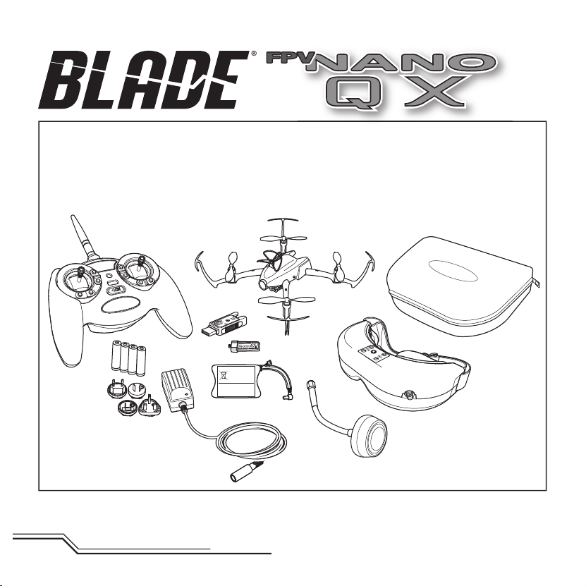
Box Contents
• Blade® FPV nano QX
• 150mAh 1S 3.7V 45C Li-Po Battery
• 1S USB Li-Po Charger, 350 mAh
• MLP4DSM
• 4 AA Batteries
FPV System:
• Fat Shark Teleporter QVGA Headset
• 720p 30fps 15Mbps Camera
• 5.8GHz Video Transmitter and Receiver
• 760mAh 2S 7.4V Li-Po Battery
• 2S Li-Po DC Charger with AC Power Supply
Li-Po BATTERY PACK
7.4V 760mAh
EN
4
Page 5
Table of Contents
First Flight Preparation .....................................................6
Flying Checklist ...............................................................6
Charging Warnings........................................................... 6
Low Voltage Cutoff (LVC) ..................................................7
Installing the Transmitter Batteries (RTF) .......................... 7
Flight Battery Charging ....................................................7
Installing the Flight Battery ..............................................8
Transmitter and Receiver Binding .....................................9
Transmitter Control ........................................................10
Flight Mode and Rate Selection (RTF) .............................11
Flight Mode Selection (BNF) ........................................... 11
Transmitter Setup Table ................................................. 12
LED Codes ..................................................................... 12
Understanding the Primary Flight Controls .....................13
4-in-1 Control Unit Function ........................................... 14
Headset Battery Charging .............................................15
Setting Up the Headset ..................................................15
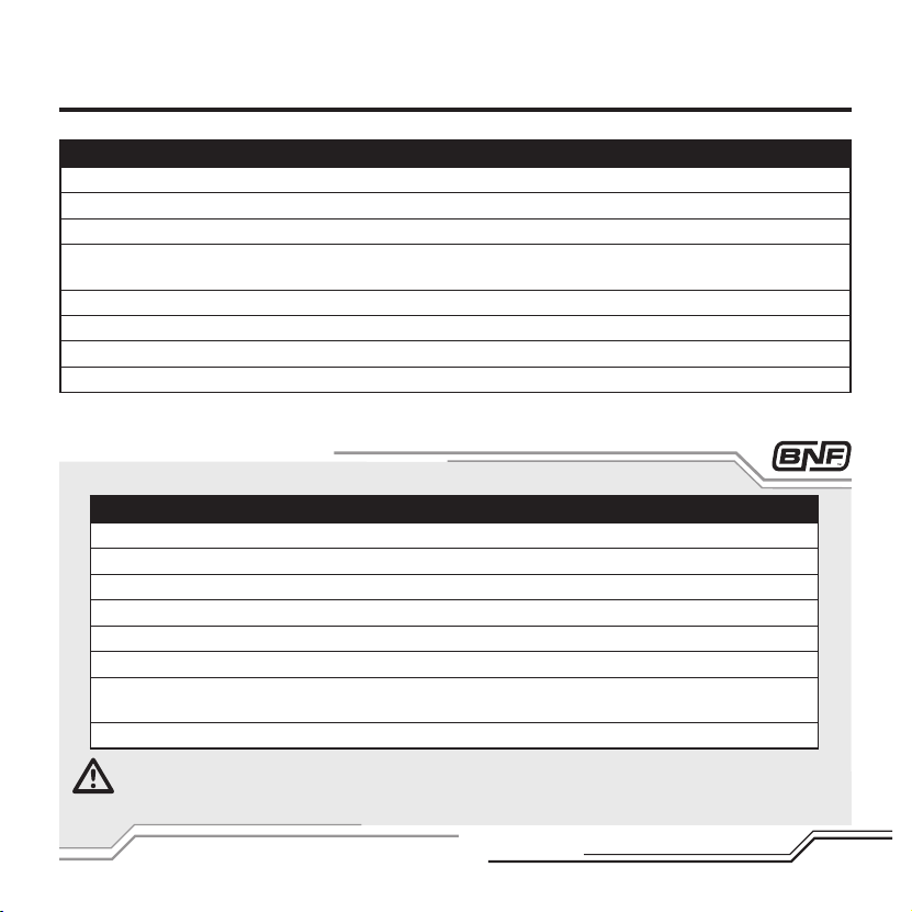
Specifications
Length
Height
Airframe
Motors
On-board Electronics
Battery
Charger
Transmitter
FPV System
5.51 in (140mm)
1.18 in (30mm)
Components RTF BNF
Blade FPV nano QX
6mm Brushed
4-in-1 mixer/ESCs/Gyro
150mAh 1S 3.7V 45C Li-Po
1S USB Li-Po Charger, 350 mAh
MLP4DSM
Fat Shark Teleporter QVGA Headset
720p 30fps 15Mbps Camera
5.8GHz Video Transmitter and Receiver
760mAh 2S 7.4V Li-Po Battery
2S Li-Po DC Charger with AC Power Supply
Display Adjustment .......................................................16
Digital Head Tracking ....................................................16
Using the Ultra Micro FPV System ................................. 16
Flying the nano QX .........................................................17
Post-Flight Inspection and Maintenance Checklist .......... 18
Caring for the Video Transmitter Antenna ....................... 19
FPV Troubleshooting ......................................................19
SAFE Technology ...........................................................19
Exploded View ............................................................... 20
Parts Listings .................................................................21
Optional Parts ................................................................ 21
Troubleshooting Guide ................................................... 22
Limited Warranty ........................................................... 24
Warranty and Service Contact Information .....................25
FCC Information .............................................................26
Compliance Information for the European Union .............27
Propeller Diameter
Flying Weight
To register your product online,visit www.bladehelis.com
1.97 in (50mm)
.63 oz (18 g)
Included Included
Installed Installed
Installed Installed
Included Included
Included Included
Included Required
Included Required
Included Included
Included Included
Included Required
Included Required
5
EN
Page 6
First Flight Preparation
• Remove and inspect contents
• Begin charging the fl ight battery
• Install the fl ight battery in the quadcopter
(once it has been fully charged)
• Program your computer transmitter
• Bind your transmitter
• Familiarize yourself with the controls
• Find a suitable area for fl ying
Charging Warnings
The battery chargers (EFLC1008 and FSV1802) included
with your quadcopter have been designed to safely charge
the Li-Po batteries.
CAUTION: All instructions and warnings must be
followed exactly. Mishandling of Li-Po batteries can result in a fi re, personal injury and/or property
damage.
• By handling, charging or using the included Li-Po
battery, you assume all risks associated with lithium
batteries.
• If at any time the battery begins to balloon or swell,
discontinue use immediately. If charging or discharging,
discontinue and disconnect. Continuing to use, charge
or discharge a battery that is ballooning or swelling can
result in fi re.
• Always store the battery at room temperature in a dry
area for best results.
• Always transport or temporarily store the battery in a
temperature range of 40–120º F (5–49° C). Do not store
battery or model in a car or direct sunlight. If stored in a
hot car, the battery can be damaged or even catch fi re.
Flying Checklist
❏ Always turn the transmitter on fi rst
❏ Plug the fl ight battery into the lead from the
4-in-1 control unit
❏ Allow the 4-in-1 control unit to initialize and
arm properly
❏ Fly the model
❏ Land the model
❏ Unplug the fl ight battery from the 4-in-1
control unit
❏ Always turn the transmitter off last
• Always charge batteries away from fl ammable
materials.
• Always inspect the battery before charging.
• Always disconnect the battery after charging, and
let the charger cool between charges.
• Always constantly monitor the temperature of the
battery pack while charging.
• ONLY USE A CHARGER SPECIFICALLY DESIGNED TO
CHARGE LI-PO BATTERIES. Failure to charge the battery
with a compatible charger may cause a fi re resulting in
personal injury and/or property damage.
• Never discharge Li-Po cells to below 3V under load.
• Never cover warning labels with hook and loop strips.
• Never leave charging batteries unattended.
• Never charge batteries outside recommended levels.
• Never charge damaged batteries.
• Never attempt to dismantle or alter the charger.
• Never allow minors to charge battery packs.
• Never charge batteries in extremely hot or cold places
(recommended between 40–120° F (5–49° C) or place in
direct sunlight.
EN
6
Page 7
Low Voltage Cuto (LVC)
When a Li-Po battery is discharged below 3V, the battery may become damaged and may no longer accept a charge.
The nano QX 4-in-1 control unit protects the fl ight battery from over-discharge using Low Voltage Cutoff (LVC). Before the
battery charge decreases too much, LVC becomes active. Power to the motors decrease and the LED on the 4-in-1 control
unit blinks, showing some battery power is reserved for fl ight control and safe landing.
When the motor power decreases, please land the aircraft immediately and recharge the fl ight battery.
Disconnect and remove the Li-Po battery from the aircraft after use to prevent trickle discharge. During storage, make
sure the battery charge does not fall below 3V.
NOTICE: Repeated fl ying to LVC will damage the battery.
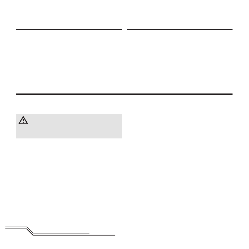
Installing the Transmitter Batteries (RTF)
Install 4 AA batteries into the transmitter, noting polarity. Replace the
transmitter batteries when the power LED fl ashes and the transmitter
beeps.
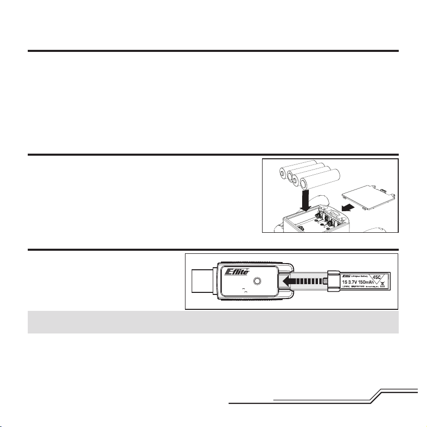
Flight Battery Charging
Your aircraft comes with a 1S 3.7V DC Li-Po battery
charger and 1S 3.7V 150mAh 45C Li-Po battery.
Refer to the charging warnings. It is recommended
to charge the battery pack while you are inspecting
the aircraft. The fl ight battery will be required to
confi rm proper aircraft operation in future steps.
NOTICE: Charge only batteries that are cool to the touch and are not damaged. Look at the battery to make sure it is not
damaged e.g., swollen, bent, broken or punctured.
1. Insert the charger into a USB port. The charger only uses power from the USB port, it will not connect to your computer.
USB power supplies, such as those used to charge cellular phones, can also be used.
2. Slide the battery into the slot on the charger and press it into the charge jack/connector located at the bottom of the slot.
The end cap of the battery is specifi cally designed to allow the battery to fi t into the slot one way (usually with the label
on the battery facing outward) to prevent reverse polarity connection, however, check for proper alignment and polarity.
USB Li-Po
Charger
DC Input:5.0V 350mA
DC Output:4.2V 300mA
SOLID RED LED
–Charging
LED OFF
–Charge
Complete
EFLC1008
7
EN
Page 8
3. Always disconnect the fl ight battery from the charger immediately upon completion of charging.
CAUTION: Only use chargers specifi cally designed to charge the included Li-Po battery. Failure to do so could
result in fi re, causing injury or property damage.
CAUTION: Never exceed the recommended charge rate.
LED Indications
When you make the connection successfully, the LED on the charger turns solid red, indicating charging has begun. Charging
a fully discharged (not over-discharged) 150mAh battery takes approximately 30–40 minutes. The light goes out when the
charge is complete.
Solid Red: Charging
OFF: Max Charge
CAUTION: Once charging is complete, immediately remove the battery. Never leave a battery connected to the charger.
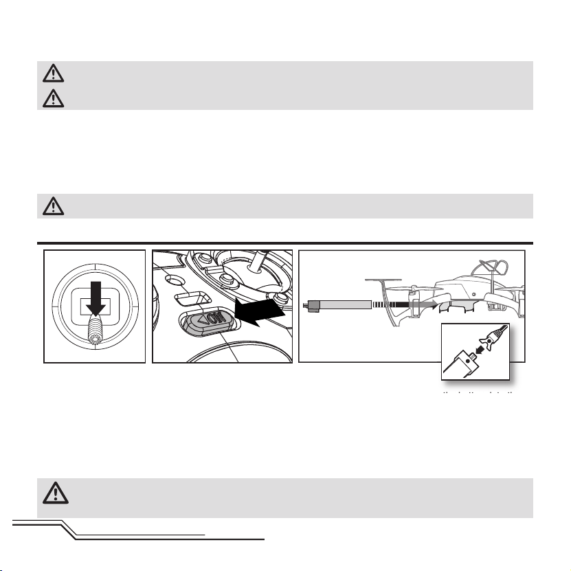
Installing the Flight Battery
12 3
4
1. Lower the throttle and throttle trim to the lowest settings.
2. Power on the transmitter.
3. Install the battery by sliding it into the battery mounting slot below the 4-in-1 control unit. Slide the battery into the
slots with the label facing downward so that the battery key, molded into the battery end-cap, comes in contact with
the key on the battery slot.
4. Connect the battery cable to the 4-in-1 control unit, matching the red mark on the battery to the red mark on the
connector.
5. Place the nano QX on its skids on a fl at surface and leave the aircraft still until the LED on the 4-in-1 control unit is
solid blue (not blinking).
CAUTION: Always disconnect the Li-Po battery from the aircraft when not fl ying to avoid over-discharging the
battery. Batteries discharged to a voltage lower than the lowest approved voltage may become damaged,
resulting in loss of performance and potential fi re when batteries are charged.
EN
8
Page 9
Transmitter and Receiver Binding
Your RTF transmitter comes prebound to the model. If you need to re-bind, follow the directions below.
MLP4DSM Binding Procedure
1. Disconnect the fl ight battery from the quadcopter.
2. Center all trims on your transmitter.
3. Power off the transmitter and move the throttle stick to the down/off position.
4. Connect the fl ight battery in the quadcopter. The LED on the 4-in-1 control unit fl ashes red during initialization, then fl ashes
blue when it is ready to bind.
5. When the blue light is fl ashing, push in and hold down the left stick while powering on the transmitter (you will hear a ‘click’).
6. Release the left stick. The transmitter will beep and the power LED will blink.
7. The quadcopter is bound when the LED on the 4-in-1 control unit is solid blue (not blinking).
8. Disconnect the fl ight battery and power the transmitter off.
If you encounter problems, obey binding instructions and refer to the troubleshooting guide for other instructions. If needed, contact the appropriate Horizon Product Support offi ce. For a list of compatible DSM
To bind or re-bind your FPV nano QX to your chosen transmitter, please follow the directions below.
General Binding Procedure
1. Disconnect the fl ight battery from the quadcopter.
2. Refer to the Transmitter Setup Table to correctly setup your transmitter.
3. Center all trims on your transmitter.
4. Power off the transmitter and move all switches to the 0 position. Move the throttle to the low/off position.
5. Connect the fl ight battery in the quadcopter. The blue LED on the 4-in-1 control unit fl ashes after 5 seconds.
6. Put the transmitter into bind mode while powering on the transmitter.
7. Release the bind button/switch after 2–3 seconds. The quadcopter is bound when the blue LED on the
4-in-1 control unit turns solid.
8. Disconnect the fl ight battery and power the transmitter off.
CAUTION: When using a Futaba® transmitter with a Spektrum™ DSM2®/DSMX® module, you must reverse
the throttle channel and rebind. Refer to your Spektrum module manual for binding and failsafe instructions.
Refer to your Futaba transmitter manual for instructions on reversing the throttle channel.
®
transmitters, please visit www.bindnfl y.com.
9
EN
Page 10

RTF
Du
se
Transmitter Control
A
H
Bind/
Flight mode
selection
G
F
E
B
Dual rate
selection
C
D
When pressed down, trim buttons make a sound that increases or decreases in pitch at each pressing. The middle or
neutral trim position is heard as a middle tone in the pitch range of the sounds. The end of the control range is sounded
by a series of beeps.
HA B CDEFG H
Mode 1 Power LED/
fl ight mode
Aileron (Left/Right)
Throttle (Up/Down)
Throttle
Trim
Aileron
Trim
ON/OFF
Switch
Rudder
Trim
Elevator Trim
Rudder (Left/Right)
Elevator (Up/Down)
indicator
Mode 2 Power LED/
fl ight mode
indicator
Aileron (Left/Right)
Elevator (Up/
Down)
Elevator Trim
Aileron
Trim
ON/OFF
Switch
Rudder
Trim
Throttle
Trim
Rudder (Left/Right)
Throttle (Up/Down)
EN
10
Page 11

Flight Mode and Rate Selection – RTF
RTF
The nano QX RTF model comes with the Blade® MLP4DSM transmitter. This transmitter’s fl ight mode selection feature lets the pilot
change between stability mode and agility mode.
• When powered on, this transmitter is automatically in
stability mode and high rate.
• Change fl ight modes by pressing and releasing the left control stick
while the transmitter is powered on. Change rates by pressing and
releasing the right control stick.
• In low-rate mode, the controls cannot reach their maximum values.
This mode is typically preferred by pilots looking for smoother/
easier control response during fi rst time use.
• In high-rate mode, the controls can reach their maximum values. This mode is typically preferred by experienced
pilots who are ready for fast forward fl ight and aerobatic maneuvers (loops, rolls, etc.).
• Stability mode is shown by the fl ight control board on the quadcopter glowing solid blue. When fl own in stability
mode, the nano QX will limit the bank angle with full control input and return the aircraft to a neutral fl ight position
when you release the elevator/aileron stick. This mode is typically preferred by pilots during fi rst time use.
• Agility mode is shown by the fl ight control board on the quadcopter glowing solid red. When fl own in agility mode,
the model will not return to a neutral fl ight position when you release the controls. This mode is typically preferred
by experienced pilots who are ready for fast forward fl ight and aerobatic maneuvers (loops, rolls, etc.).
Flight Mode Selection – BNF
If you purchased a BNF nano QX, the channel 6 switch on your transmitter will select fl ight modes. When the fl ight
control board on the quadcopter is solid blue, the fl ight mode is set to self-stabilizing mode. When the light is solid red,
the quadcopter is in agility mode. See the table on the following page for specifi c setup information.
11
EN
Page 12

Transmitter Setup Table
Using 30% exponential on aileron and elevator is recommended.
Transmiter "Model
MLP4DSM N/A Depress Left Stick N/A
DX4e N/A Trainer/Bind N/A Rate N/A N/A N/A
DX5e N/A Trainer/Bind N/A Rate N/A N/A N/A
DX6i Acro
DX7 Acro
DX7S/8 Acro Trainer/Bind
DX6, DX9,
DX18
Type"
Acro Trainer/Bind
Stability to
Agility Switch
Cycle Flaps Pos
fi rst time 0-1, each
time after 1-0-1
Cycle Flaps Pos
fi rst time 0-2, each
time after 2-0-2
Stability to
Agility TX Setup
In FLAPS Menu:
Set NORM FLAP
to Down 20
N/A ELEV-AIL D/R N/A 100% 70%
In Switch Select
Menu: Set Flap to
Inh, Set Trainer to
Aux1
In Channel Assign
Menu Go to Next:
Set 6 AUX1: to I
Dual Rate
Switch
Depress Right
Stick
ELEV-AIL D/R N/A 100% 70%
ELEV-AIL D/R Rev 100% 70%
ELEV-AIL D/R Rev 100% 70%
Aux1
Reverse
N/A N/A N/A
High Rate Low Rate
LED Codes
Equipment LED Color LED Status Operation
Rapid Blink Bind Mode
Blue
Quadcopter
Red
RTF Transmitter Red
Slow Blink No Link To Transmitter
Solid Stability Mode
Blink Low Battery
Solid Agility Mode
Blink Low Rate
Solid Hi Rate
EN
12
Page 13

Understanding the Primary Flight Controls
If you are not familiar with the controls of your nano QX, take a few minutes to familiarize yourself with them before
attempting your fi rst fl ight.
Throttle
Left Side View Left Side View
Descend
Throttle up
Rudder
Rudder left
Elevator
Climb
Throttle down
Rudder right
Nose Yaws RightNose Yaws Left
Left Side View Left Side View
ForwardElevator down
Elevator up
Backward
13
EN
Page 14

Aileron
Rear ViewRear View
Aileron left
Left
Aileron right
Right
4-in-1 Control Unit Function
The unique Control Unit installed in your nano QX is a lightweight combination of main motor electronic speed controls
(ESCs), mixers, the SAFE™ sensor unit, and a DSM2/DSMX receiver. The 4-in-1 unit is also equipped with blue and red
status indicator LEDs.
• Before each fl ight, ALWAYS power on the transmitter before connecting the fl ight battery to the 4-in-1 unit. After each
fl ight, disconnect the fl ight battery from the 4-in-1 unit before powering off the transmitter.
Connecting the fl ight battery before powering on the transmitter can start the binding process. Please see the Transmitter
and Receiver Binding section of this manual for more information.
• The 4-in-1 unit will arm the motors when the throttle stick is in the lowest possible position and the throttle trim is at
the middle or a lower than middle position (the middle position is indicated by a longer than usual beep/tone). If this is
the fi rst test fl ight, or a test fl ight following repairs, also center the rudder, aileron and elevator trims.
• With the transmitter turned on and the transmitter LED glowing solid RED, connect the fl ight battery to the 4-in-1 unit.
• After the fl ight battery is connected, place the nQX on a level surface. The 4-in-1 unit status LED should glow solid
BLUE within a few seconds.
• DO NOT move, sway or pretend to fl y the quadcopter after connecting the fl ight battery. Movement can stop unit initialization and SAFE calibration. If the quadcopter is moved before the 4-in-1 unit status LED glows solid BLUE, disconnect
then connect the fl ight battery to the 4-in-1 unit.
• When the 4-in-1 unit status LED glows solid BLUE, the control unit is initialized and ready for fl ight.
• As long as you set the throttle stick and trim to the correct positions during the initialization process, the ESC or motors
will be armed. Use caution after arming, as the propellers will turn at throttle stick input.
EN
14
Page 15

Headset Battery Charging
LED Indications
Solid Red: Charging
Solid Green: Max Charge
CAUTION: Only use a charger specifi cally designed
to charge a Li-Po battery. Failure to do so could
result in fi re, causing injury or property damage.
CAUTION: Always disconnect the battery from the
Li-Po BATTERY PACK
7.4V 760mAh
charger immediately upon completion of charging.
Low Battery Warning
The headset will beep when the battery voltage is low.
As the headset battery voltage continues to drop, the beep
rate will increase. Recharge the headset battery as soon as possible.
Setting Up the Headset
CAUTION: Do not power the headset or downlink kit without the antenna attached. Doing so will damage the
transmitter and receiver amplifi ers. Amplifi er damage is not covered by warranty.
NOTICE: Do not leave the headset exposed to direct sunlight. Sunlight is magnifi ed by the optics and will burn holes in the
LCD color fi lter (appears as white open areas). This is not covered by warranty.
Keep the headset in its protective case
when not in use.
1. Attach the antenna to the headset.
2. Connect the fully-charged Li-Po battery
pack to the headset.
3. Look through the headset and press
the Channel Up/Down buttons.
Clean channels will have a consistent
static background. Channels with
interference will display horizontal
static lines. Select one of the clean
channels. A long beep sounds on channels 1 and 7.
4. Once you have chosen a clean channel in the headset, select the same channel on the video receiver.
Spektrum Ultra Micro
FPV Transmitter Channels
Channel 1 5470 MHz
Channel 2 5760 MHz
Channel 3 5780 MHz
Channel 4 5800 MHz
Channel 5 5820 MHz
Channel 6 5840 MHz
Channel 7 5860 MHz
15
EN
Page 16

Display Adjustment
• Press Left or Right on the Display Button to adjust the video contrast in the headset.
• Press Forward or Back on the Display Button to adjust the video brightness in the headset.
• Press Down on the Display Button to change the video zoom in the headset. The normal
display (16:9) shows the entire image with black bars on the top & bottom. The zoom
display (4:3) maximizes the image in the headset and is used with digital head tracking.
Display button
Digital Head Tracking
• Long Press: Depressing the Display Button toggles head tracker mode (active/deactivate). With digital head tracking active,
the image will zoom in and the image will digitally pan and tilt in response to head motion.
• Short Press: Resets center reference position (both analog/digital).
Refer to the SPMVR1100 or SPMVS1100 headset manual for more information about head tracker functions.
Using the Ultra Micro FPV System
Consult local laws and ordinances before operating FPV equipment. In some areas, FPV operation may be limited or
prohibited. You are responsible for operating this product in a legal and responsible manner.
1. Power on your radio transmitter, then power on the aircraft.
2. Power on the headset to make sure the channel is clear and then the video transmitter.
3. Perform a range test before flying.
Tip: If you are prone to motion sickness, sit in a chair. If you start to suffer from motion sickness while fl ying, lower your
chin against your chest.
Fly in open areas, away from people, trees, cars, and buildings. The range of the system can be impacted by any obstructions blocking your signal. It is normal to see break up in the video going behind trees and other obstacles.
NOTICE: We do not recommend using the ultra micro FPV system in low light.
EN
16
Page 17

Flying the nano QX
• After confi rming the rotor blades rotate in the correct direction, test the motor response controls.
• Adjust the throttle to a low level of power where the quadcopter begins to get “light” on its landing skids.
• Move the rudder stick a small amount to the right. The nose of the quadcopter should start to rotate
to the right (clockwise).
• Move the rudder stick a small amount to the left. The nose of the quadcopter should start to rotate to the left
(counter-clockwise). If the nose moves to the right, please refer to the Troubleshooting Guide.
• Move the elevator control stick forward. The two REAR landing skids should lift from the fl oor.
• Move the elevator control stick backward. The two FRONT landing skids should lift from the fl oor.
• Move the aileron stick right. The two LEFT landing skids should lift from the fl oor.
• Move the aileron stick left. The two RIGHT landing skids should lift from the fl oor.
• When rotors turn correctly and respond correctly to controls, your nano QX is ready for its fi rst fl ight!
First Flight
• Increase the throttle until the model is approximately 2 ft. (600mm) off the ground in a low-level hover and concentrate
on balancing the throttle stick’s position so that the nano QX holds a steady hover altitude. In some cases, you may
need to make a few short “hops” to an altitude of just a few inches until you become familiar with the control inputs
and trim settings required to maintain a steady hover and altitude.
The nano QX requires minor throttle adjustments to maintain its altitude in hover. Remember to keep these throttle
adjustments as minimal as possible. Large adjustments could result in a loss of control and/or a possible crash.
• While attempting to establish a low-level hover, check to see if any trim adjustments are required to help keep the
nano QX from constantly drifting in various directions. If you fi nd that it constantly drifts without any directional control
input, land the model before making any adjustments to the trim settings. Additional details regarding the
location and function of the trim buttons are in the “Understanding the Primary Flight Controls” section of this manual.
– If the nose of the nano QX rotates to the left or right, adjust the rudder trim.
– If the nano QX continually drifts forward or backward, adjust the elevator trim.
– If the nano QX continually drifts to the left or right, adjust the aileron trim.
Continue making minor trim adjustments until the machine hovers at a low altitude with very little drifting and directional
control input. If the nano QX is your fi rst multicopter or helicopter, seek the help of an experienced pilot to trim the model
for you before making your fi rst fl ight.
• With your nano QX properly trimmed and maintaining a stable low-level hover, practice using the rudder, elevator and
aileron controls to familiarize yourself with the machine’s responses to control inputs. Remember to keep the control
inputs as minimal as possible.
17
EN
Page 18

• When comfortable with low-level hovering, you can transition to hovering and fl ying the nano QX at higher altitudes of
three to four feet. At these higher altitudes, you will become comfortable with the fl ight characteristics of the aircraft.
• Don’t be afraid to set the nano QX down on the ground quickly by lowering the throttle when approaching walls or
other obstacles to help prevent propeller strikes.
Once you have gained experience and confi dence in hovering the nano QX, you can attempt more advanced
maneuvers including:
• Forward Flight
• Backward Flight
• Skidding Takeoffs
TIP: These are all possible with the RTF transmitter. When using a computer transmitter, however, increase the
travel beyond 100% on aileron, elevator or rudder for maximum control authority.
• Pirouettes
• Spot Landings
• Skidding Landings
• Circuits (Circles)
• Figure 8s
• Flips and Rolls
Post-Flight Inspection and Maintenance Checklist
√
Cleaning
Motors Replace the motor when the model will not fl y steady or veers off when doing a climb out.
Wiring Make sure the wiring does not block moving parts. Replace damaged wiring and loose connectors.
Fasteners
Propellers
EN
Make sure the battery is not connected before cleaning. Remove dust and debris with a soft brush or
a dry, lint-free cloth.
Make sure there are no loose screws, other fasteners or connectors. Do not over-tighten metal
screws in plastic parts. Tighten screws so the parts are mated together, then turn screw only 1/8th
of a turn more.
Make sure there is no damage to the propellers or other parts that move at high speed. Damage to
these parts includes cracks, burrs, chips or scratches. Replace damaged parts before fl ying.
18
Page 19

Caring for the Video Transmitter Antenna
™
If your video transmitter antenna gets bent or fl attened as a
consequence of a hard landing, bend the antenna so the lobes
are at a 45° angle to the bottom plane of the antenna, as shown
at the right.
45°
45°
FPV Troubleshooting
Problem Possible Cause Solution
No image, display is
completely dark
No image, display is
glowing dark gray
Static on all channels Video transmitter power is off Make sure the video transmitter LED is on
Horizontal lines in the
headset display
Head tracking is not
moving in correct
direction
No power supplied to the video transmitter
or headset
Video source switch is set to external receiver
mode
Digital interference on the selected channel Choose a cleaner channel
Digital head tracking is reversed
Check the power connections.
Make sure the battery is fully charged
Ensure the video source switch is switched to headset
mode
Refer to the SPMVR1100 or SPMVS1100 headset
manual for more information on how to reset digital
head tracking
Technology
Revolutionary SAFE™ (Sensor Assisted Flight Envelope) technology uses an innovative combination of multi-axis sensors
and software that allows model aircraft to know its position relative to the horizon. This spatial awareness is utilized to create
a controlled fl ight envelope the aircraft uses to maintain a safe region of bank and pitch angles so you can fl y more safely.
Far beyond stability, this level of protection offers multiple modes so the pilot can choose to develop his or her skills with a
greater degree of security and fl ight control that always feels crisp and responsive.
SAFE technology delivers:
• Flight envelope protection you can enable at the fl ip of a switch.
• Multiple modes let you adapt SAFE technology to your skill level instantly.
Best of all, sophisticated SAFE technology doesn’t require any work to enjoy. Every aircraft with SAFE installed is ready to use
and optimized to offer the best possible fl ight experience. FlySAFERC.com
19
EN
Page 20

Exploded View
1
3
5
24
11
EN
8
10 10
7
6
9
9
20
12
Page 21

Parts Listings
Part # Description
BLH7200 FPV nano QX RTF
BLH7280 FPV nano QX BNF W/O Goggles
BLH7201 Blue Canopy: FPV nano QX
1
BLH7202 Prop CCW Blue (2): Nano QX
2
BLH7203 Prop CW Blue (2): Nano QX
3
BLH7204 Prop CCW Clear (2): Nano QX
4
BLH7205 Prop CW Clear (2): Nano QX
5
BLH2706 UM camera mount: Nano QX
6
BLH7639C Main Frame Clear: Nano QX
7
BLH2707 4-in-1 Rx/ESCs/Gyro: FPV nano QX
8
9 BLH7603 Motor, CW Rotation: nQ X
10 BLH7604 Motor, CCW Rotation: nQ X
Optional Parts
Part # Description
EFLC1006
BLH7620 Prop, CW Rotation, Blk (2): nQ X
BLH7621 Prop, CCW Rotation, Blk (2): nQ X
BLH7620G Prop, CW Rotation, Grn (2): nQ X
BLH7621G Prop, CCW Rotation, Grn (2): nQ X
BLH7620Y Prop, CW Rotation, Yel (2): nQ X
BLH7621Y Prop, CCW Rotation, Yel (2): nQ X
Celectra 1S 3.7v Variable Rate DC Li-Po Charger
DX5e DSMX 5-Channel Transmitter Only
DX6i DSMX 6-Channel Transmitter Only
Part # Description
EFLC1008 1S USB Li-Po Charger, 350mA: nQ X
11 EFLB1501S45 150mAh 1-Cell 3.7V 45c LiPo
12 SPMVA1100
EFLH1064/B
EFLH10641
SPMVR1100
FSV1701
Part # Description
Ultra Micro FPV Camera and Video
Transmitter
MLP4DSM 4CH Transmitter, 2.4GHz
Mode 2
MLP4DSM 4CH Transmitter, 2.4GHz
Mode 1
Teleporter V4 Video Headset with
Head Tracking
1000mAh 2S 7.4V Video
Headset Li-Po Battery
DX6 DSMX 6-Channel Transmitter Only
DX7s DSMX 7-Channel Transmitter Only
DX8 DSMX 8-Channel Transmitter Only
DX9 DSMX 9-Channel Transmitter Only
DX9 Black Edition DSMX 9-Channel
Transmitter Only
DX18 Gen2 DSMX 18-Channel
Transmitter Only
21
EN
Page 22

Troubleshooting Guide
Problem Possible Cause Solution
Nano QX control response is
inconsistent or requires extra
trim to neutralize movement
Nano QX will not respond to
throttle
Nano QX does not function
and smells burnt after con-
necting the fl ight battery
Nano QX has reduced fl ight
time or is underpowered
Aircraft not initialized on a level surface
Battery not correctly placed in
battery slot
Throttle too high and/or throttle trim is
too high
nano QX moved during initialization
Throttle channel is reversed
Flight battery connected with the
wrong polarity
Flight battery charge is low Completely recharge the fl ight battery
Inadequate power to fl ight battery
charger
Flight battery is damaged
Flight conditions might be too cold
Disconnect the fl ight battery, center the
control trim and re-initialize the quadcopter
Adjust battery position so quadcopter
balances in the center of the frame
Reset controls with the throttle stick
and throttle trim at the lowest setting
Disconnect the flight battery and
re-initialize the nano QX while keeping
the quadcopter from moving
Disconnect fl ight battery, reverse the
throttle channel on the transmitter,
recconnect fl ight battery
Replace the 4-in-1 board. Connect the
fl ight battery noting proper polarity
Use a different USB power source for the
charger
Replace the fl ight battery and follow the
fl ight battery instructions
Make sure the battery is warm (room temperature) before use
EN
22
Page 23

Problem Possible Cause Solution
LED on receiver fl ashes rapidly
and aircraft will not respond to
transmitter (during binding)
LED on the receiver fl ashes
rapidly and the nano QX will
not respond to the transmitter
(after binding)
Crashes immediately
upon lift-off
Transmitter too near aircraft during
binding process
Bind switch or button was not held
while transmitter was powered on
Aircraft or transmitter is too close to
large metal object, wireless source or
another transmitter
Less than a 5-second wait between
fi rst powering on the transmitter and
connecting the fl ight battery to the
nano QX
The nano QX is bound to a different
model memory (ModelMatch™
transmitters only)
Flight battery or transmitter battery
charge is too low
Aircraft or transmitter is too close to
large metal object, wireless source or
another transmitter
Propellers in wrong locations or
incorrect fl ight mode selected
Power off the transmitter. Move the
transmitter a larger distance from the
aircraft. Disconnect and reconnect the
fl ight battery to the aircraft. Follow the
binding instructions
Power off transmitter and repeat bind
process
Move aircraft and transmitter to another
location and attempt binding again
Leave the transmitter powered on.
Disconnect and reconnect the fl ight
battery to the nano QX
Select the correct model memory on the
transmitter. Disconnect and reconnect the
fl ight battery to the nano QX
Replace or recharge batteries
Move aircraft and transmitter to another
location and attempt connecting again
Make necessary adjustments
23
EN
Page 24

Limited Warranty
What this Warranty Covers
Horizon Hobby, LLC, (Horizon) warrants to the original purchaser that the product purchased (the "Product") will be free from
defects in materials and workmanship at the date of purchase.
What is Not Covered
This warranty is not transferable and does not cover (i) cosmetic damage, (ii) damage due to acts of God, accident, misuse, abuse, negligence, commercial use, or due to improper
use, installation, operation or maintenance, (iii) modification of
or to any part of the Product, (iv) attempted service by anyone
other than a Horizon Hobby authorized service center, (v)
Product not purchased from an authorized Horizon dealer, or
(vi) Product not compliant with applicable technical regulations.
OTHER THAN THE EXPRESS WARRANTY ABOVE, HORIZON
MAKES NO OTHER WARRANTY OR REPRESENTATION, AND
HEREBY DISCLAIMS ANY AND ALL IMPLIED WARRANTIES,
INCLUDING, WITHOUT LIMITATION, THE IMPLIED WARRANTIES
OF NON-INFRINGEMENT, MERCHANTABILITY AND
FITNESS FOR A PARTICULAR PURPOSE. THE PURCHASER
ACKNOWLEDGES THAT THEY ALONE HAVE DETERMINED THAT
THE PRODUCT WILL SUITABLY MEET THE REQUIREMENTS OF
THE PURCHASER’S INTENDED USE.
Purchaser’s Remedy
Horizon’s sole obligation and purchaser’s sole and exclusive
remedy shall be that Horizon will, at its option, either (i) service, or (ii) replace, any Product determined by Horizon to be
defective. Horizon reserves the right to inspect any and all
Product(s) involved in a warranty claim. Service or replacement decisions are at the sole discretion of Horizon. Proof
of purchase is required for all warranty claims. SERVICE OR
REPLACEMENT AS PROVIDED UNDER THIS WARRANTY IS THE
PURCHASER’S SOLE AND EXCLUSIVE REMEDY.
Limitation of Liability
HORIZON SHALL NOT BE LIABLE FOR SPECIAL, INDIRECT,
INCIDENTAL OR CONSEQUENTIAL DAMAGES, LOSS OF
PROFITS OR PRODUCTION OR COMMERCIAL LOSS IN ANY
WAY, REGARDLESS OF WHETHER SUCH CLAIM IS BASED IN
CONTRACT, WARRANTY, TORT, NEGLIGENCE, STRICT LIABILITY
OR ANY OTHER THEORY OF LIABILITY, EVEN IF HORIZON HAS
BEEN ADVISED OF THE POSSIBILITY OF SUCH DAMAGES.
Further, in no event shall the liability of Horizon exceed the
individual price of the Product on which liability is asserted. As
Horizon has no control over use, setup, final assembly, modification or misuse, no liability shall be assumed nor accepted
for any resulting damage or injury. By the act of use, setup
or assembly, the user accepts all resulting liability. If you as
the purchaser or user are not prepared to accept the liability
associated with the use of the Product, purchaser is advised to
return the Product immediately in new and unused condition
to the place of purchase.
Law
These terms are governed by Illinois law (without regard to
conflict of law principals). This warranty gives you specific
legal rights, and you may also have other rights which vary
from state to state. Horizon reserves the right to change or
modify this warranty at any time without notice.
WARRANTY SERVICES
Questions, Assistance, and Services
Your local hobby store and/or place of purchase cannot provide warranty support or service. Once assembly, setup or use
of the Product has been started, you must contact your local
distributor or Horizon directly. This will enable Horizon to better
answer your questions and service you in the event that you
may need any assistance. For questions or assistance, please
visit our website at www.horizonhobby.com, submit a Product
Support Inquiry, or call the toll free telephone number referenced in the Warranty and Service Contact Information section
to speak with a Product Support representative.
Inspection or Services
If this Product needs to be inspected or serviced and is compliant in the country you live and use the Product in, please
use the Horizon Online Service Request submission process
found on our website or call Horizon to obtain a Return
Merchandise Authorization (RMA) number. Pack the Product
securely using a shipping carton. Please note that original
boxes may be included, but are not designed to withstand
the rigors of shipping without additional protection. Ship via
a carrier that provides tracking and insurance for lost or
EN
24
Page 25

damaged parcels, as Horizon is not responsible for merchandise until it arrives and is accepted at our facility. An Online
Service Request is available at http://www.horizonhobby.com/
content/_service-center_render-service-center. If you do not
have internet access, please contact Horizon Product Support
to obtain a RMA number along with instructions for submitting your product for service. When calling Horizon, you will be
asked to provide your complete name, street address, email
address and phone number where you can be reached during
business hours. When sending product into Horizon, please
include your RMA number, a list of the included items, and a
brief summary of the problem. A copy of your original sales
receipt must be included for warranty consideration. Be sure
your name, address, and RMA number are clearly written on
the outside of the shipping carton.
NOTICE: Do not ship LiPo batteries to Horizon. If you
have any issue with a LiPo battery, please contact the
appropriate Horizon Product Support office.
Warranty Requirements
For Warranty consideration, you must include your orig-
inal sales receipt verifying the proof-of-purchase date.
Provided warranty conditions have been met, your Product will
be serviced or replaced free of charge. Service or replacement
decisions are at the sole discretion of Horizon.
Non-Warranty Service
Should your service not be covered by warranty, ser-
vice will be completed and payment will be required
without notification or estimate of the expense unless
the expense exceeds 50% of the retail purchase cost.
By submitting the item for service you are agreeing to payment of the service without notification. Service estimates are
available upon request. You must include this request with your
item submitted for service. Non-warranty service estimates
will be billed a minimum of ½ hour of labor. In addition you
will be billed for return freight. Horizon accepts money orders
and cashier’s checks, as well as Visa, MasterCard, American
Express, and Discover cards. By submitting any item to Horizon
for service, you are agreeing to Horizon’s Terms and Conditions
found on our website http://www.horizonhobby.com/content/_
service-center_render-service-center.
ATTENTION: Horizon service is limited to Product compliant in the country of use and ownership. If received,
a non-compliant Product will not be serviced. Further,
the sender will be responsible for arranging return
shipment of the un-serviced Product, through a carrier
of the sender’s choice and at the sender’s expense.
Horizon will hold non-compliant Product for a period
of 60 days from notification, after which it will be discarded.
Warranty and Service Contact Information
Country of Purchase Horizon Hobby Contact Information Address
United States of
America
Horizon Service Center
(Repairs and Repair Requests)
Horizon Product Support
(Product Technical Assistance)
Sales
servicecenter.horizonhobby.
com/RequestForm/
www.quickbase.com/db/
bghj7ey8c?a=GenNewRecord
888-959-2304
sales@horizonhobby.com
888-959-2304
4105 Fieldstone Rd
Champaign, Illinois, 61822 USA
25
EN
Page 26

Country of Purchase Horizon Hobby Contact Information Address
United Kingdom
Germany
France
China
Service/Parts/Sales:
Horizon Hobby Limited
Horizon Technischer Service service@horizonhobby.de
Sales: Horizon Hobby GmbH +49 (0) 4121 2655 100
Service/Parts/Sales:
Horizon Hobby SAS
Service/Parts/Sales:
Horizon Hobby – China
sales@horizonhobby.co.uk
+44 (0) 1279 641 097
infofrance@horizonhobby.com
+33 (0) 1 60 18 34 90
info@horizonhobby.com.cn
+86 (021) 5180 9868
Units 1–4 , Ployters Rd, Staple Tye
Harlow, Essex, CM18 7NS, United
Kingdom
Christian-Junge-Straße 1
25337 Elmshorn, Germany
11 Rue Georges Charpak
77127 Lieusaint, France
Room 506, No. 97 Changshou Rd.
Shanghai, China 200060
FCC Information
This device complies with part 15 of the FCC rules. Operation is subject to the following two conditions: (1) This device
may not cause harmful interference, and (2) this device must accept any interference received, including interference that
may cause undesired operation.
CAUTION: Changes or modifi cations not expressly approved by the party responsible for compliance could void
the user’s authority to operate the equipment.
This product contains a radio transmitter with wireless technology which has been tested and found to be compliant with
the applicable regulations governing a radio transmitter in the 2.400GHz to 2.4835GHz frequency range.
FPV System:
FCC ID: 2ABYQFSV1251.
Nano QX:
This product contains a radio transmitter with wireless
technology which has been tested and found to be compliant with the applicable regulations governing a radio transmitter in the 2.400GHz to 2.4835GHz frequency range.
IC Information
IC ID: 12280A-125X. This device complies with Industry Canada license-exempt RSS standard(s). Operation is subject
to the following two conditions: (1) this device may not cause interference, and (2) this device must accept any interference,
including interference that may cause undesired operation of the device.
EN
26
Page 27

Compliance Information for the European Union
Declaration of Conformity Declaration of Conformity
(in accordance with ISO/IEC 17050-1)
No. HH2014100202
Product(s): Nano QX FPV RTF
Item Number(s): BLH7200, BLH7200M1
Equipment class: 1
The object of declaration described above is in conformity with
the requirements of the specifi cations listed below, following
the provisions of the European R&TTE Directive 1999/5/EC,
EMC Directive 2004/108/EC, and LVD Directive 2006/95/EC:
Nano QX
EN 300-328 V1.7.1: 2006
EN 301 489-1 V1.7.1: 2006
EN 301 489-17 V1.3.2: 2008
EN60950-1:2006+A11:2009+A1:2010+A12: 2011
EN61000-3-2:2006+A1:2009+A2:2009
EN61000-3-3:2008
EN55022:2010 + AC:2011
EN55024:2010
FPV System
EN 300 440-1 V1.6.1
EN 300 440-2 V1.4.1
EN 301 489-1 V1.9.2: (2011-09)
EN 301 489-3 V1.6.1 (2013-08)
EN55022:2010 + AC:2011
EN55024:2010
EN 62479:2010
EN 60950-1:2006+A11:2009+A1:2010+A12: 2011
Signed for and
on behalf of:
Horizon Hobby, LLC
Champaign, IL USA
October 2 , 2014
Executive Vice President
Mike Dunne
Product Divisions
Horizon Hobby, LLC
(in accordance with ISO/IEC 17050-1)
No. HH2014100203
Product(s): Nano QX FPV BNF without Goggles
Item Number(s): BLH7280
Equipment class: 1
The object of declaration described above is in conformity with
the requirements of the specifi cations listed below, following
the provisions of the European R&TTE Directive 1999/5/EC,
EMC Directive 2004/108/EC, and LVD Directive 2006/95/EC:
Nano QX
EN 301 489-1 V1.7.1: 2006
EN 301 489-17 V1.3.2: 2008
EN60950-1:2006+A11:2009+A1:2010+A12: 2011
EN61000-3-2:2006+A1:2009+A2:2009
EN61000-3-3:2008
EN55022:2010 + AC:2011
EN55024:2010
FPV Camera
EN 300 440-1 V1.6.1
EN 300 440-2 V1.4.1
EN 301 489-1 V1.9.2: (2011-09)
EN 301 489-3 V1.6.1 (2013-08)
EN 62479:2010
EN 60950-1:2006+A11:2009+A1:2010+A12: 2011
Signed for and
on behalf of:
Horizon Hobby, LLC
Champaign, IL USA
October 2 , 2014
Executive Vice President
Mike Dunne
Product Divisions
Horizon Hobby, LLC
27
EN
Page 28

Instructions for disposal of WEEE by users in the European Union
This product must not be disposed of with other waste. Instead, it is the user’s responsibility to dispose of their
waste equipment by handing it over to a designated collections point for the recycling of waste electrical and
electronic equipment. The separate collection and recycling of your waste equipment at the time of disposal will
help to conserve natural resources and ensure that it is recycled in a manner that protects human health and
the environment. For more information about where you can drop off your waste equipment for recycling, please
contact your local city offi ce, your household waste disposal service or where you purchased the product.
EN
28
Page 29

©2014 Horizon Hobby, LLC.
Blade, E-fl ite, SAFE, the SAFE logo, DSM, DSM2, DSMX, Bind-N-Fly, the BNF logo, Celectra, ModelMatch
and the Horizon Hobby logo are trademarks or registered trademarks of Horizon Hobby, LLC.
The Spektrum trademark is used with permission of Bachmann Industries, Inc. Futaba is a registered trademark of Futaba Denshi
Kogyo Kabushiki Kaisha Corporation of Japan. All other trademarks, service marks or logos are property of their respective owners.
Patents pending. Created 08/14 45369.1 BLH7200
IT
112
 Loading...